PreSens Fibox 4 trace User manual

Fibox 4 & Fibox 4 trace
Fiber optic oxygen transmitters
TRANSMITTERS
Instruction Manual


© 2013 PreSens Precision Sensing GmbH
Fibox 4 & Fibox 4 trace
Specification:
Fiber optic oxygen transmitters for use
with non-invasive oxygen sensors & sensor probes
Software:
PreSens Datamanager
Document filename: IM_FB4-FB4trace_dv1
All rights reserved. No parts of this work may be reproduced in any form or by any means -
graphic, electronic, or mechanical, including photocopying, recording, taping, or information
storage and retrieval systems - without the written permission of the publisher.
Products that are referred to in this document may be either trademarks and/or registered
trademarks of the respective owners. The publisher and the author make no claim to these
trademarks.
While every precaution has been taken in the preparation of this document, the publisher and
the author assume no responsibility for errors or omissions, or for damages resulting from the
use of information contained in this document or from the use of programs and source code
that may accompany it. In no event shall the publisher and the author be liable for any loss of
profit or any other commercial damage caused or alleged to have been caused directly or
indirectly by this document.
Specifications may change without prior notice.
Manufacture
r
PreSens
Precision Sensing GmbH
Josef-Engert-Str. 11
93053 Regensburg, Germany
Phone +49 941 94272100
Fax +49 941 94272111
www.PreSens.de


© 2013 PreSens Precision Sensing GmbH
Table of Contents
1Preface ........................................................................................................................ 3
2Description of the Fibox 4 & Fibox 4 trace Transmitter.......................................... 4
2.1 Scope of Delivery....................................................................................................... 5
2.2 Top Panel.................................................................................................................... 6
2.3 Bottom Panel.............................................................................................................. 6
2.4 Control Panel ............................................................................................................. 7
2.5 Barcode Reader ......................................................................................................... 8
3Installation .................................................................................................................. 9
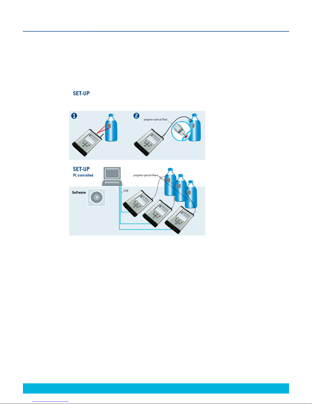
3.1 Set-up.......................................................................................................................... 9
3.2 Software Installation................................................................................................ 10
3.3 Adjustment of the Regional Settings of the Operating System........................... 13
3.4 Battery Usage & Charging ...................................................................................... 15
4Operation .................................................................................................................. 17
4.1 Starting the Device .................................................................................................. 17
4.2 User........................................................................................................................... 19
4.3 Sensors..................................................................................................................... 21
4.3.1 Add a New Sensor ................................................................................................... 22
4.3.1.1 Add a New Sensor via Barcode .............................................................................. 23
4.3.1.2 Add a New Sensor Manually ................................................................................... 24
4.3.2 Calibrate Sensors .................................................................................................... 26
4.3.2.1 Calibration via Barcode........................................................................................... 27
4.3.2.2 Manual Calibration................................................................................................... 27
4.4 Measurement Settings............................................................................................. 30
4.4.1 Temperature Compensation ................................................................................... 31
4.4.2 Pressure Compensation.......................................................................................... 31
4.4.3 Measurement Conditions ........................................................................................ 32
4.4.4 Salinity Compensation ............................................................................................ 32
4.4.5 Interval ...................................................................................................................... 33
4.4.6 Logging & Data Management.................................................................................. 33
4.5 Measurement............................................................................................................ 35
4.5.1 Simple Screen .......................................................................................................... 35
4.5.2 Details Screen .......................................................................................................... 38
4.5.3 Graph Screen ........................................................................................................... 39
4.5.4 Scan a New Sensor.................................................................................................. 41
4.6 Device Settings ........................................................................................................ 42
4.6.1 Device Settings Screen ........................................................................................... 42
4.6.2 Energy Management................................................................................................ 44
4.6.3 About Screen............................................................................................................ 46
4.6.4 Sensor Details Screen ............................................................................................. 47
4.7 Subsequent Data Handling ..................................................................................... 47
4.7.1 Sensor Data Management ....................................................................................... 49
4.7.2 Measurement Data Management ............................................................................ 55
4.7.3 User Management .................................................................................................... 57
4.7.4 Change the Working Directory ............................................................................... 58
4.8 Error Notification & Troubleshooting..................................................................... 59

© 2013 PreSens Precision Sensing GmbH
4.9 Software Menu Structure ........................................................................................ 60
5Technical Data.......................................................................................................... 61
5.1 Specifications........................................................................................................... 61
6Operational Notes .................................................................................................... 63
6.1 Optical Output.......................................................................................................... 63
6.2 USB-Power Adapter................................................................................................. 63
6.3 Changing the Rechargeable Batteries ................................................................... 63
6.4 Barcode Reader Specifications .............................................................................. 65
6.5 Pt100 Configuration................................................................................................. 66
6.6 Maintenance ............................................................................................................. 71
6.7 Service ...................................................................................................................... 71
7CE and FCC Conformity .......................................................................................... 72
8Concluding Remarks ............................................................................................... 73


3
Fibox 4 & Fibox 4 trace
© 2013 PreSens Precision Sensing GmbH
Preface
1 Preface
You have chosen a new, innovative technology for measuring oxygen.
The Fibox 4 & Fibox 4 trace are compact, portable, completely stand-alone fiber optic oxygen
transmitters. The data management and export is PC supported.
The Fibox 4 & Fibox 4 trace are developed especially for small fiber optic oxygen sensors,
flow-through cells and non-invasive sensors. They are based on a novel technology, which
creates very stable, internally referenced measured values. This allows a more flexible use of
oxygen sensors in various fields of interest.
Optical oxygen sensors (also called optrodes) have several important features:
They are small.
Their signal does not depend on the flow rate of the sample.
They can be physically divided from the measuring system which allows a non-
invasive measurement.
They can be used in disposables.
Therefore, they are ideally suited for the examination of small sample volumes, for highly
parallelized measurements in disposables, and for biotechnological applications. A set of
different oxygen minisensors, flow-through cells and non-invasive sensors is available to
make sure you have the sensor which matches your application.
Please feel free to contact our service team to find the best solution for your application.
Your PreSens Team
PLEASE READ THE FOLLOWING INSTRUCTIONS CAREFULLY BEFORE WORKING
WITH THIS DEVICE. WHEN DISREGARDING THESE INSTRUCTIONS THE SAFETY OF
THE DEVICE CAN BE IMPAIRED.

4
© 2013 PreSens Precision Sensing GmbH
Fibox 4 & Fibox 4 trace Description of the Fibox 4 & Fibox 4 trace
2 Description of the Fibox 4 & Fibox 4
trace Transmitter
The Fibox 4 & Fibox 4 trace are precise single channel fiber optic trace oxygen transmitters
with temperature compensation, and additional compensation of pressure and salinity. The
Fibox 4 is designed for small fiber optic oxygen sensors with sensor type PSt3 (limit of
detection 0.03 % oxygen, 15 ppb dissolved oxygen). The Fibox 4 trace additionally works with
PSt6 type sensors (limit of detection 0.002 % oxygen, 1 ppb dissolved oxygen), and the ultra
low oxygen sensor PSt9 (limit of detection 0.5 ppm, 0 – 200 ppm gaseous oxygen).
The Fibox 4 & Fibox 4 trace are portable, completely stand-alone devices with a color display
and control buttons designed to be operated even with heavy gloves on. Easy sensor
handling and calibration is realized with the implemented barcode reader. The Fibox 4 &
Fibox 4 trace have an integrated, rechargeable battery and built-in memory. Connection to a
PC as well as charging the battery is done via USB. For measurement or sensor data transfer
the Fibox 4 & Fibox 4 trace are used with a comfortable PC software. An extended, database
supported software version that allows controlling up to 10 Fibox 4 / Fibox 4 trace
simultaneously is also available (please contact our service team for further information!).
Fibox 4 Fibox 4 trace
Compatible sensor type PSt3 PSt3, PSt6, PSt9
Features:
High precision
Portable & completely stand-alone device
Temperature, pressure & salinity compensation
Sensor handling & calibration via barcode
Fig. 1 Fibox 4 trace, fiber optic trace oxygen transmitter for use
with non-invasive ox
yg
en sensors & sensor
p
robes

5
© 2013 PreSens Precision Sensing GmbH
Fibox 4 & Fibox 4 trace Description of the Fibox 4 & Fibox 4 trace
2.1 Scope of Delivery
Fibox 4 OR Fibox 4 trace, fiber optic trace oxygen transmitter with protection kit
PreSens Datamanager software (CD)
USB cable
USB-Power adapter (5 VDC, min. 1 A) with different connector pieces
Optional:
Temperature sensor Pt100
Extended software
Additionally required equipment (not supplied):
Oxygen-sensitive chemical optical sensor
You can find mini sensors – mounted into different types of housings – on
www.presens.de/products
PC / Notebook for comfortable data transfer and export:
System requirements:
Microsoft®Windows®XP, VistaTM, 7, or 8; Processor power according to minimum
requirements of the respective operating system
Fig. 2 Case with all delivered equipment

6
© 2013 PreSens Precision Sensing GmbH
Fibox 4 & Fibox 4 trace Description of the Fibox 4 & Fibox 4 trace
2.2 Top Panel
The top panel is equipped with a connector for the fiber optic sensor, a connector for the
temperature sensor, and the barcode reader.
ELEMENT DESCRIPTION FUNCTION
SMA SMA fiber
connector
Connect the fiber optic sensor here.
BR Barcode Reader Scan sensor barcodes for sensor identification and
calibration.
TEMP Connector for
Pt100 temperature
sensor
Connect the Pt100 temperature sensor for
temperature compensated measurements here.
2.3 Bottom Panel
The bottom panel is equipped with the USB connector for charging the battery or connecting
the device to a PC / notebook. A screw cap gives access to the battery compartment.
Fig. 3 Transmitter top panel
Fi
g
. 4 Transmitter bottom
p
anel
SMA TEMP
BR
USB
BATT

7
© 2013 PreSens Precision Sensing GmbH
Fibox 4 & Fibox 4 trace Description of the Fibox 4 & Fibox 4 trace
ELEMENT DESCRIPTION FUNCTION
USB Connector for the USB
cable.
Connect the device with an USB cable to the power
supply for charging or to your PC / notebook. Use
the provided parts only!
BATT Battery compartment Open the screw cap to get access to the battery
compartment (please refer to chapter 6.3).
2.4 Control Panel
The Fibox 4 & Fibox 4 trace are completely stand-alone devices. The LCD display and the
buttons allow operating the transmitter without connection to a PC / notebook. In the lower
part of the display the functions of the buttons in the respective menu, submenu or window
are shown. Use the buttons for navigating on the screen, and to make settings; pressing the
respective button will perform the respective function (see Fig. 5).
Fig. 5 Control panel of the Fibox 4 & Fibox 4 trace

8
© 2013 PreSens Precision Sensing GmbH
Fibox 4 & Fibox 4 trace Description of the Fibox 4 & Fibox 4 trace
2.5 Barcode Reader
The integrated barcode reader on the top panel of the Fibox 4 & Fibox 4 trace facilitates
sensor handling and management. The barcode reader can be activated in different menus or
submenus. As soon as the barcode reader is activated place the Fibox 4 / Fibox 4 trace about
10 cm from the respective sensor barcode; the target cross has to be aimed at the barcode.
Reducing or increasing the distance between barcode and barcode reader can speed up the
scanning process. A notification window opens on the screen showing the message “Sensor
successfully scanned!” when the scanning process is done. In case the scanning was not
successful the screen shows the message “No Barcode recognized”.
!If the battery symbol in the status bar (see chapter 4.1) is flashing the battery status is
very low. The barcode reader will not work with very low battery. Connect the Fibox 4 /
Fibox 4 trace to the power supply or a PC / notebook and recharge the batteries.
Fig. 6 Scanning a sensor barcode

9
© 2013 PreSens Precision Sensing GmbH
Fibox 4 & Fibox 4 trace Installation
3 Installation
3.1 Set-up
A typical set-up is shown in Fig. 7. After barcode scan and sensor recognition the sensor spot
is read out non-invasively via a polymer optical fiber which is connected to the transmitter.
The Fibox 4 & Fibox 4 trace are completely stand-alone devices, and have to be connected to
a PC / notebook for data transfer only. However the transmitters can be connected to a PC /
notebook via USB and controlled with the extended software version (see Fig. 7, bottom).
This software allows operating up to 10 Fibox 4 / Fibox 4 trace simultaneously (please contact
our service team for further information!).
The software is compatible with Microsoft®Windows®XP, VistaTM, 7, or 8.
Remove the rubber cap from the optical sensor connector (SMA connector) and keep the cap.
After measurements or for storing the transmitter the rubber cap should be put back on to
keep the optical sensor connector clean.
!It is recommended to clean the SMA connector with a dust free cleaning wipe or a
cleaning implement for SMA connectors before the measurement.
Fig. 7 Set-up for Fibox 4 & Fibox 4 trace. Top: Stand-alone use; bottom: PC controlled
use with the extended software, e. g. parallel control of 3 transmitters.

10
© 2013 PreSens Precision Sensing GmbH
Fibox 4 & Fibox 4 trace Installation
Remove the protective cap from the male plug on the polymer optical fiber and insert it in the
SMA connector of the Fibox 4 / Fibox 4 trace. The safety nut has to be screwed on.
There is a red mark on the temperature sensor connector of the Fibox 4 / Fibox 4 trace. The
temperature sensor plug has a red mark as well. Match those two marks before inserting the
temperature sensor plug into the connector on the transmitter front panel; else the plug might
get damaged.
3.2 Software Installation
The Fibox 4 & Fibox 4 trace are delivered with the PreSens Datamanager software, which
allows transferring sensor, user and measurement data between the transmitter and a PC /
notebook. Furthermore, barcodes can be created with this software.
(If you require the extended software version, please contact our service team for further
information!)
1. Connect the Fibox 4 / Fibox 4 trace to the PC / notebook via USB.
2. Please close all other applications as they may interfere with the software.
3. Insert the supplied CD-ROM into the respective drive.
4. If no dialog opens automatically, use the explorer to open the file menu on the CD. Click
the file “PreSens Datamanager_x.x.x.x_Setup_FW.exe” to start the installation.
5. Select Setup Language (English / German) and press OK. The Setup – PreSens
Datamanager window opens; follow the instructions of the PreSens Datamanager Setup
Wizard, which will guide you through the installation and press Next to proceed. When
you have finished installation pre-settings you can press the Install button.
Fig. 8 Connecting a Pt100 temperature sensor to the transmitter

11
© 2013 PreSens Precision Sensing GmbH
Fibox 4 & Fibox 4 trace Installation
6. Please wait while the PreSens Datamanager software is installed on your PC / notebook.
7. In case .NET Framework 4 is not installed on your computer, the installation will start
automatically. You will have to accept the license terms to continue, check the box
beneath the license window and click Install. Installing .NET Framework 4 will require a
few minutes.
Fig. 9 PreSens Datamanager Setup Wizard
Fig. 10 The software is being installed.

12
© 2013 PreSens Precision Sensing GmbH
Fibox 4 & Fibox 4 trace Installation
8. When PreSens Datamanager installation is completed click the Finish button.
9. Start the software by double clicking the software icon on your desktop or by selecting
PreSens Datamanager in your programs list.
Fig. 12 Installation is completed. Click Finish to close the
PreSens Datamanager Setup Wizard
Fig. 11 .NET Framework license agreement

13
© 2013 PreSens Precision Sensing GmbH
Fibox 4 & Fibox 4 trace Installation
3.3 Adjustment of the Regional Settings of the Operating
System
To change the regional settings on your PC press Start and go to the Control Panel. Choose
Regional and Language Options.
Select the Regional Options tab (e.g. English (United States)) and click Customize.
A window opens; select the Numbers tab and choose the dot `.´ in the Decimal Symbol drop
down menu. In the drop down menu Digit grouping symbol you have to choose space ` ´.
Then press Apply and OK.
Fig. 14 Regional and Language Options window
Fig. 13 Control Panel – Classic View

14
© 2013 PreSens Precision Sensing GmbH
Fibox 4 & Fibox 4 trace Installation
Click Customize again and go to the Date tab now. In the drop down menu Short date
format you have to select `dd.MM.yy´ and choose the dot `.´ in Date separator. Again press
Apply and OK.
Press OK in the Regional and Language Options window, and you have finished adjusting
the regional settings.
Fig. 15 Customize Regional Options window – Numbers tab
Fig. 16 Customize Regional Options window – Date tab

15
© 2013 PreSens Precision Sensing GmbH
Fibox 4 & Fibox 4 trace Installation
3.4 Battery Usage & Charging
!In order to conserve energy the device will turn off, if not in use for more than 15
minutes. 15 minutes is the default setting, and can be changed to user requirements.
(For Energy Management Settings please refer to chapter 4.6.2.)
The Fibox 4 & Fibox 4 trace comprise rechargeable batteries for self-contained power supply.
Rechargeable batteries are subject to normal wear which is more or less pronounced
depending on operating and storage conditions. This normal wear is no defect which is
covered by the device warranty.
(For battery information, please refer to the Technical Data chapter 5.)
Battery use time (per charge) from fully charged:
Measurement mode duration approx. 16 hours (3 s Interval measurement, Default
LED Intensity, Display backlight OFF)
Standby Mode (Long Term Measurement mode activated) duration 30 days
The battery status is displayed in the status bar of the screen (see chapter 4.1).
For recharging the batteries connect the supplied USB cable to the USB connector on the
bottom panel of the Fibox 4 / Fibox 4 trace.
Then you can connect the USB cable to a USB port of a PC / notebook. The batteries will be
charged when the PC / notebook is turned on.
Fig. 17 Connecting the USB cable to transmitter
Table of contents
Other PreSens Transmitter manuals