Presenza QK031 Assembly instructions

STAINLESS STEEL
OFFSET DOUBLE
BOWL SINK
INSTALLATION GUIDE
AND USER MANUAL
Model No. QK031

2
Table of Contents
Table of Contents ...................................2
Safety Information ..................................2
Warranty ...........................................
One-Year Limited Warranty ..........................3
Warranty Claim Procedure ...........................3
Pre-Installation......................................
Planning Installation ................................4
Tools Required .....................................4
Parts Required ....................................4
Package Contents .................................5
Installation .........................................
Undermount.......................................6
Topmount.........................................9
Installing the Vanishing EdgeTM Strainer ................11
Installing the Bottom Grid ...........................11
Care and Cleaning .................................12
Service Parts .....................................13
Safety Information
READ AND SAVE THESE INSTRUCTIONS
1. Inspect your unit before proceeding. Once you unpack your
unit, check for chips, scratches, cracks, dents or scuff marks.
If any damage is noticed, do not install.
2. Use this unit only in the manner intended by the manufacturer.
If you have any questions, contact the manufacturer.
3. Installation work and plumbing must be done by qualied
person(s) in accordance with all applicable codes and
standards.
4. Protect the entire surface during installation.
CAUTION: Always wear safety goggles and gloves during
installation to prevent personal injury.
3
CONGLOMKB.COM
Please contact customer.service@conglomkb.com or 1-877-333-0098 for further assistance.
Warranty
ONE-YEAR LIMITED WARRANTY
A thorough inspection must be made before installation and any damage must be promptly reported. We will not be liable for failures or damage that
could have been discovered or avoided by proper inspection and testing prior to installation.
Conglom Kitchen & Bath warrants this product to be free from defects in materials or workmanship for one (1) year from the date of purchase. Proof
of purchase (original sales receipt) from the original consumer purchaser must be made available to Conglom Kitchen & Bath for all warranty claims.
This warranty is non-transferable and shall be voided if the unit is removed from its initial installation or if it is not installed following the manufacturer’s
instructions. It does not apply in the event of product damage due to the use of other than genuine Conglom Kitchen & Bath replacement parts,
(Replacement parts may be obtained by e-mail at customer.service@conglomkb.com or by calling 1-877-333-0098 between 8:30 am - 5:00 pm EST)
installation error, abuse, misuse or improper care and maintenance (whether performed by a plumber, contractor, service provider or member of
the purchaser’s household). The warranty excludes damage due to aggressive air or water conditions, harsh or abrasive cleaners and/or materials.
Under no circumstance shall we be held liable for personal injury or property damage resulting from improper installation or use of this product.
We will not be held liable for inconvenience caused by loss of use of this product, costs incurred for labour or materials, removal and installation
of replacement units, or any other incidental or consequential damages. Costs relating to obtaining access for repair or replacement are the
responsibility of the user.
Our obligation shall be limited to the repair or replacement of a unit (at our discretion) that may prove, by our sole examination, to be defective under
normal use and service during the warranty period.
Any failure of this product that is not traceable to a defect in material or workmanship is not covered by this warranty. These non-warrantable items
include, but are not limited to:
- Improper installation not in accordance with manufacturer’s instructions.
- Dents and/or scratches incurred during shipping, handling, or installation.
- Change in colour or nish due to chemical usage.
- Damage caused by failure to follow care and cleaning guidelines, including damage caused by the use of abrasive cleaners.
- Alterations made to the unit by the purchaser or installer.
- Damage caused by accidental impact, re, ood, freezing, and normal wear.
- Bends and warping caused by forced connections, over-tightened ttings, and inadequate support during installation.
This warranty does not extend to commercial and institutional installation or use.
WARRANTY CLAIM PROCEDURE
If a claimable defect occurs or replacement parts are needed, please contact our customer service team at customer.service@conglomkb.com or
1-877-333-0098 (8:30 am - 5 pm, EST, Monday - Friday).
Before you make your call, please ensure that you have:
- Model number or description.
- Proof of sale.
- Details regarding the defect and/or part number.
- Name(s) and address(es) of the owner and/or installer.

4
Pre-Installation
PLANNING INSTALLATION
Inspect your unit before proceeding. Check the surface for any aws or damage, including dents, bends, bumps, or scuff marks. If any damage
is noticed, do not proceed with installation. Please return the unit to place of purchase for an exchange. If there are any missing parts, please
contact the manufacturer for replacements.
You may choose to install this sink either undermount (from below the counter) or topmount (from above the counter). You must install this sink
only in a counter at least 36 in. (914 mm) wide with a solid surface that has a minimum thickness of at least 3/4 in. (19 mm).
Protect the entire surface of the product during installation to prevent damage.
TOOLS/MATERIALS REQUIRED
Measuring tape Carpenter’s square Wrenches (2)
Saber-saw or
Jig-saw
Electric drill with
3/8 in. (10 mm) drill
bit and 1 in. (25.4
mm) or 3 in. (76.2
mm) hole saw
Pipe wrench
Plumber’s putty Silicone sealant Pencil
Phillips screwdriver Hacksaw Teon tape
Safety gloves Safety goggles
PARTS REQUIRED (NOT INLCUDED)
NOTE:
Parts not shown to actual size.
Plastic
ange (2) Tail pipe (2) Connecting
nut (2) Supply lines (2)
5
CONGLOMKB.COM
Please contact customer.service@conglomkb.com or 1-877-333-0098 for further assistance.
Pre-Installation (continued)
PACKAGE CONTENTS
A
BCD
E
F
Part Description Quantity
AStainless steel sink 1
BVanishing edgeTM strainer 2
CStrainer assembly 2
DTopmount clamps 10
EUndermount clamps 10
FBottom grid 1
6
Installation
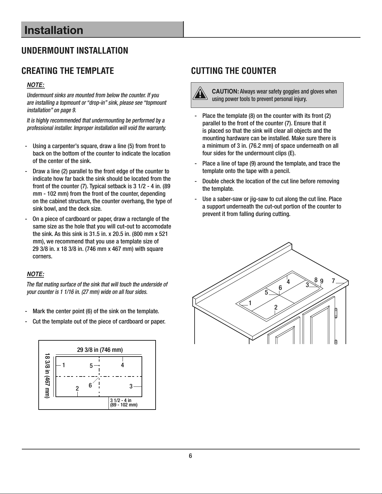
UNDERMOUNT INSTALLATION
CREATING THE TEMPLATE CUTTING THE COUNTER
NOTE:
Undermount sinks are mounted from below the counter. If you
are installing a topmount or “drop-in” sink, please see “topmount
installation” on page 9.
It is highly recommended that undermounting be performed by a
professional installer. Improper installation will void the warranty.
- Using a carpenter’s square, draw a line (5) from front to
back on the bottom of the counter to indicate the location
of the center of the sink.
- Draw a line (2) parallel to the front edge of the counter to
indicate how far back the sink should be located from the
front of the counter (7). Typical setback is 3 1/2 - 4 in. (89
mm - 102 mm) from the front of the counter, depending
on the cabinet structure, the counter overhang, the type of
sink bowl, and the deck size.
- On a piece of cardboard or paper, draw a rectangle of the
same size as the hole that you will cut-out to accomodate
the sink. As this sink is 31.5 in. x 20.5 in. (800 mm x 521
mm), we recommend that you use a template size of
29 3/8 in. x 18 3/8 in. (746 mm x 467 mm) with square
corners.
NOTE:
The at mating surface of the sink that will touch the underside of
your counter is 1 1/16 in. (27 mm) wide on all four sides.
- Mark the center point (6) of the sink on the template.
- Cut the template out of the piece of cardboard or paper.
29 3/8 in (746 mm)
3 1/2 - 4 in
(89 - 102 mm)
18 3/8 in (467 mm)
5
6
14
23
CAUTION: Always wear safety goggles and gloves when
using power tools to prevent personal injury.
- Place the template (8) on the counter with its front (2)
parallel to the front of the counter (7). Ensure that it
is placed so that the sink will clear all objects and the
mounting hardware can be installed. Make sure there is
a minimum of 3 in. (76.2 mm) of space underneath on all
four sides for the undermount clips (E).
- Place a line of tape (9) around the template, and trace the
template onto the tape with a pencil.
- Double check the location of the cut line before removing
the template.
- Use a saber-saw or jig-saw to cut along the cut line. Place
a support underneath the cut-out portion of the counter to
prevent it from falling during cutting.
1
7
5
2
4
6
9
38
7
CONGLOMKB.COM
Please contact customer.service@conglomkb.com or 1-877-333-0098 for further assistance.
Installation (continued)
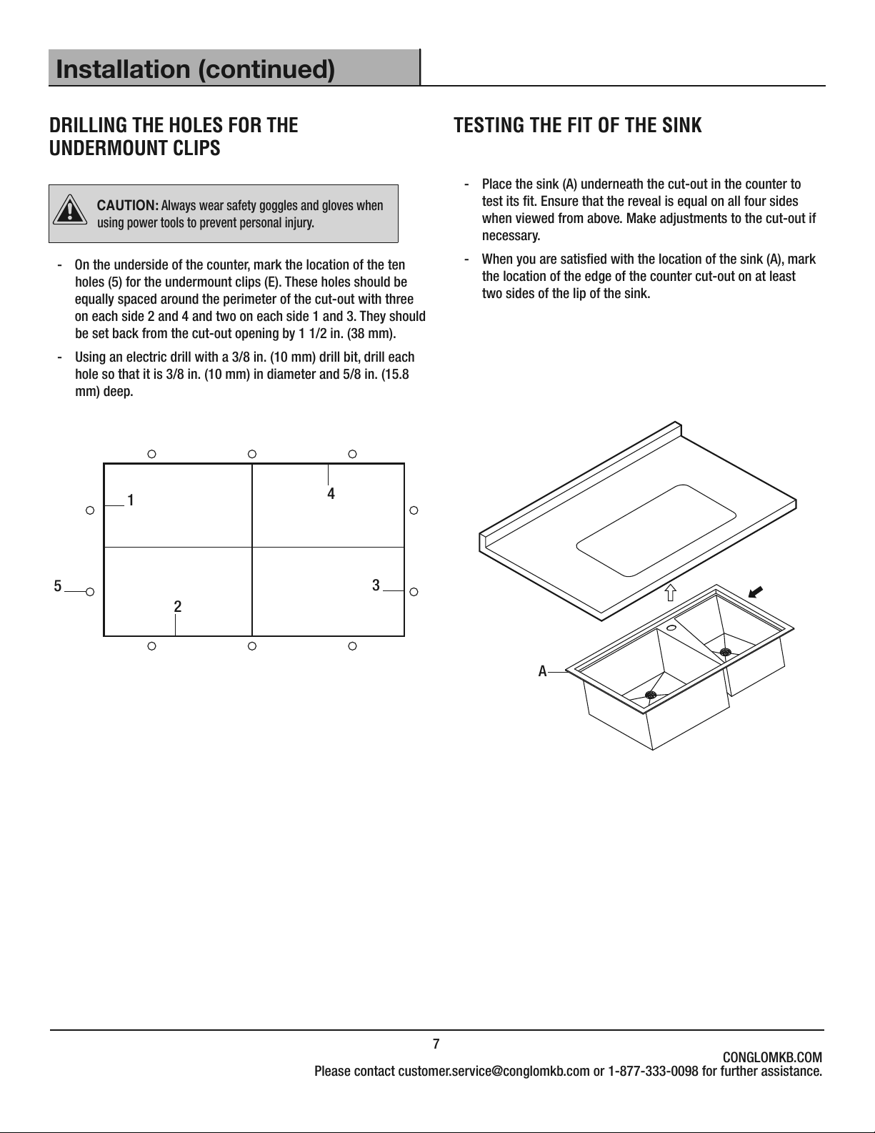
DRILLING THE HOLES FOR THE
UNDERMOUNT CLIPS
TESTING THE FIT OF THE SINK
CAUTION: Always wear safety goggles and gloves when
using power tools to prevent personal injury.
- On the underside of the counter, mark the location of the ten
holes (5) for the undermount clips (E). These holes should be
equally spaced around the perimeter of the cut-out with three
on each side 2 and 4 and two on each side 1 and 3. They should
be set back from the cut-out opening by 1 1/2 in. (38 mm).
- Using an electric drill with a 3/8 in. (10 mm) drill bit, drill each
hole so that it is 3/8 in. (10 mm) in diameter and 5/8 in. (15.8
mm) deep.
- Place the sink (A) underneath the cut-out in the counter to
test its t. Ensure that the reveal is equal on all four sides
when viewed from above. Make adjustments to the cut-out if
necessary.
- When you are satised with the location of the sink (A), mark
the location of the edge of the counter cut-out on at least
two sides of the lip of the sink.
14
5
2
3
A
8
Installation (continued)
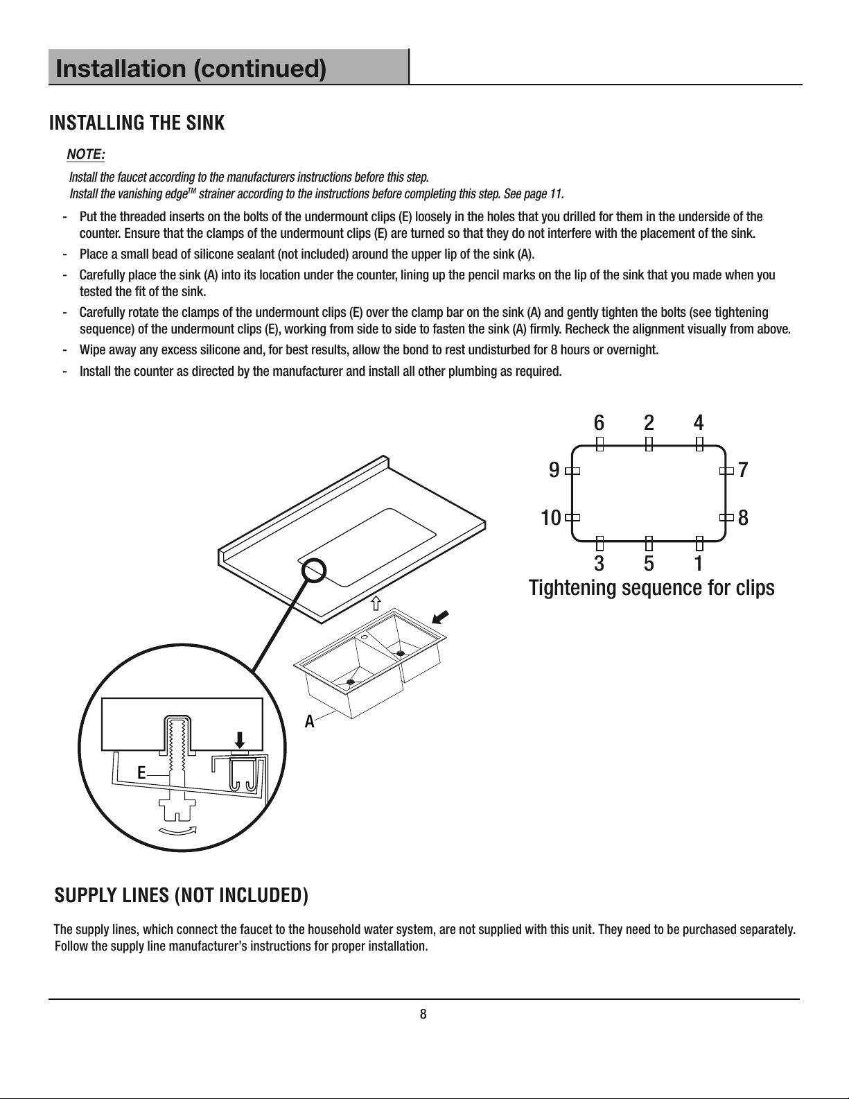
INSTALLING THE SINK
NOTE:
Install the faucet according to the manufacturers instructions before this step.
Install the vanishing edgeTM strainer according to the instructions before completing this step. See page 11.
- Put the threaded inserts on the bolts of the undermount clips (E) loosely in the holes that you drilled for them in the underside of the
counter. Ensure that the clamps of the undermount clips (E) are turned so that they do not interfere with the placement of the sink.
- Place a small bead of silicone sealant (not included) around the upper lip of the sink (A).
- Carefully place the sink (A) into its location under the counter, lining up the pencil marks on the lip of the sink that you made when you
tested the t of the sink.
- Carefully rotate the clamps of the undermount clips (E) over the clamp bar on the sink (A) and gently tighten the bolts (see tightening
sequence) of the undermount clips (E), working from side to side to fasten the sink (A) rmly. Recheck the alignment visually from above.
- Wipe away any excess silicone and, for best results, allow the bond to rest undisturbed for 8 hours or overnight.
- Install the counter as directed by the manufacturer and install all other plumbing as required.
9
6 2 4
3 5 1
7
810
Tightening sequence for clips
A
E
SUPPLY LINES (NOT INCLUDED)
The supply lines, which connect the faucet to the household water system, are not supplied with this unit. They need to be purchased separately.
Follow the supply line manufacturer’s instructions for proper installation.
9
CONGLOMKB.COM
Please contact customer.service@conglomkb.com or 1-877-333-0098 for further assistance.
Installation (continued)
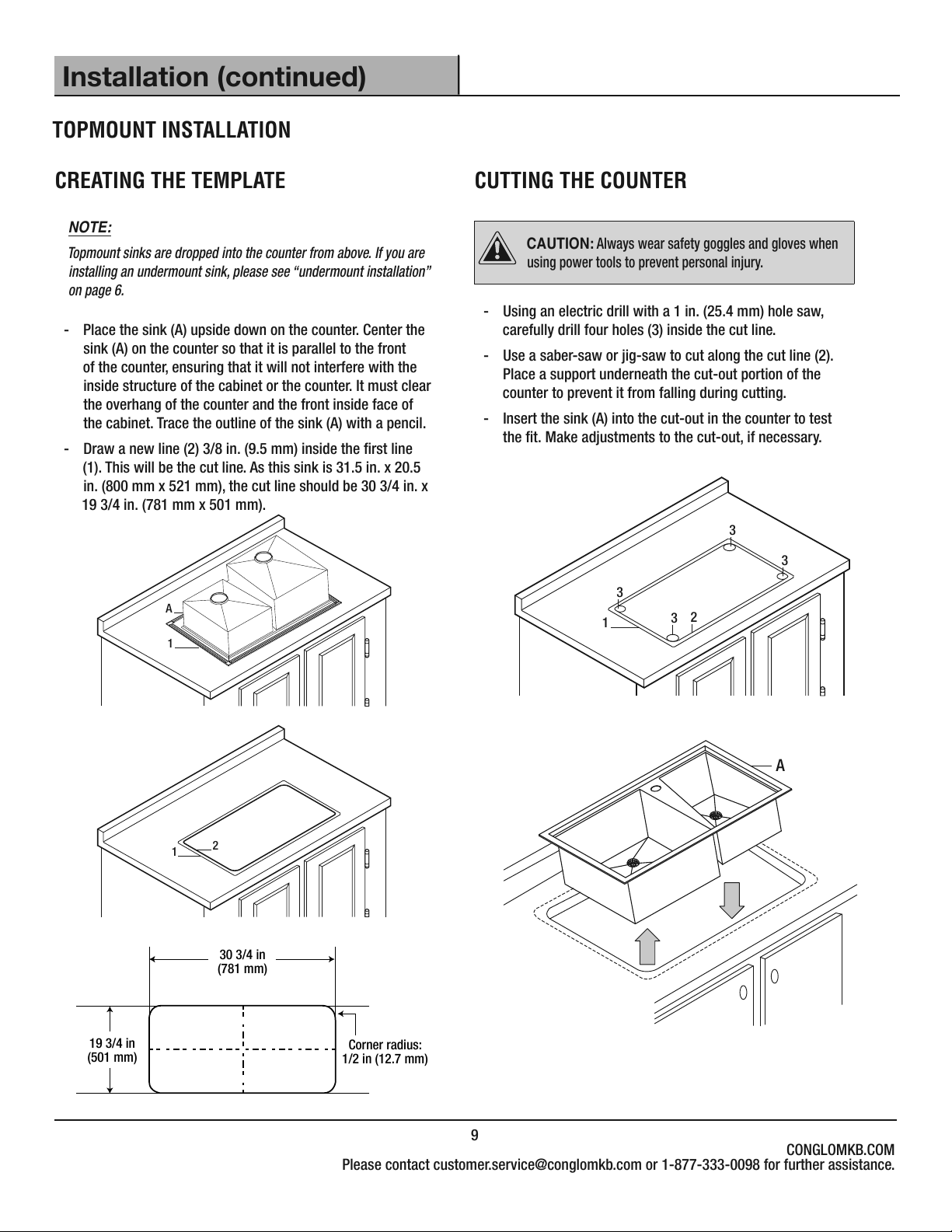
TOPMOUNT INSTALLATION
CREATING THE TEMPLATE CUTTING THE COUNTER
NOTE:
Topmount sinks are dropped into the counter from above. If you are
installing an undermount sink, please see “undermount installation”
on page 6.
- Place the sink (A) upside down on the counter. Center the
sink (A) on the counter so that it is parallel to the front
of the counter, ensuring that it will not interfere with the
inside structure of the cabinet or the counter. It must clear
the overhang of the counter and the front inside face of
the cabinet. Trace the outline of the sink (A) with a pencil.
- Draw a new line (2) 3/8 in. (9.5 mm) inside the rst line
(1). This will be the cut line. As this sink is 31.5 in. x 20.5
in. (800 mm x 521 mm), the cut line should be 30 3/4 in. x
19 3/4 in. (781 mm x 501 mm).
A
1
12
30 3/4 in
(781 mm)
19 3/4 in
(501 mm) Corner radius:
1/2 in (12.7 mm)
CAUTION: Always wear safety goggles and gloves when
using power tools to prevent personal injury.
- Using an electric drill with a 1 in. (25.4 mm) hole saw,
carefully drill four holes (3) inside the cut line.
- Use a saber-saw or jig-saw to cut along the cut line (2).
Place a support underneath the cut-out portion of the
counter to prevent it from falling during cutting.
- Insert the sink (A) into the cut-out in the counter to test
the t. Make adjustments to the cut-out, if necessary.
12
3
3
3
3
A
10
Installation (continued)
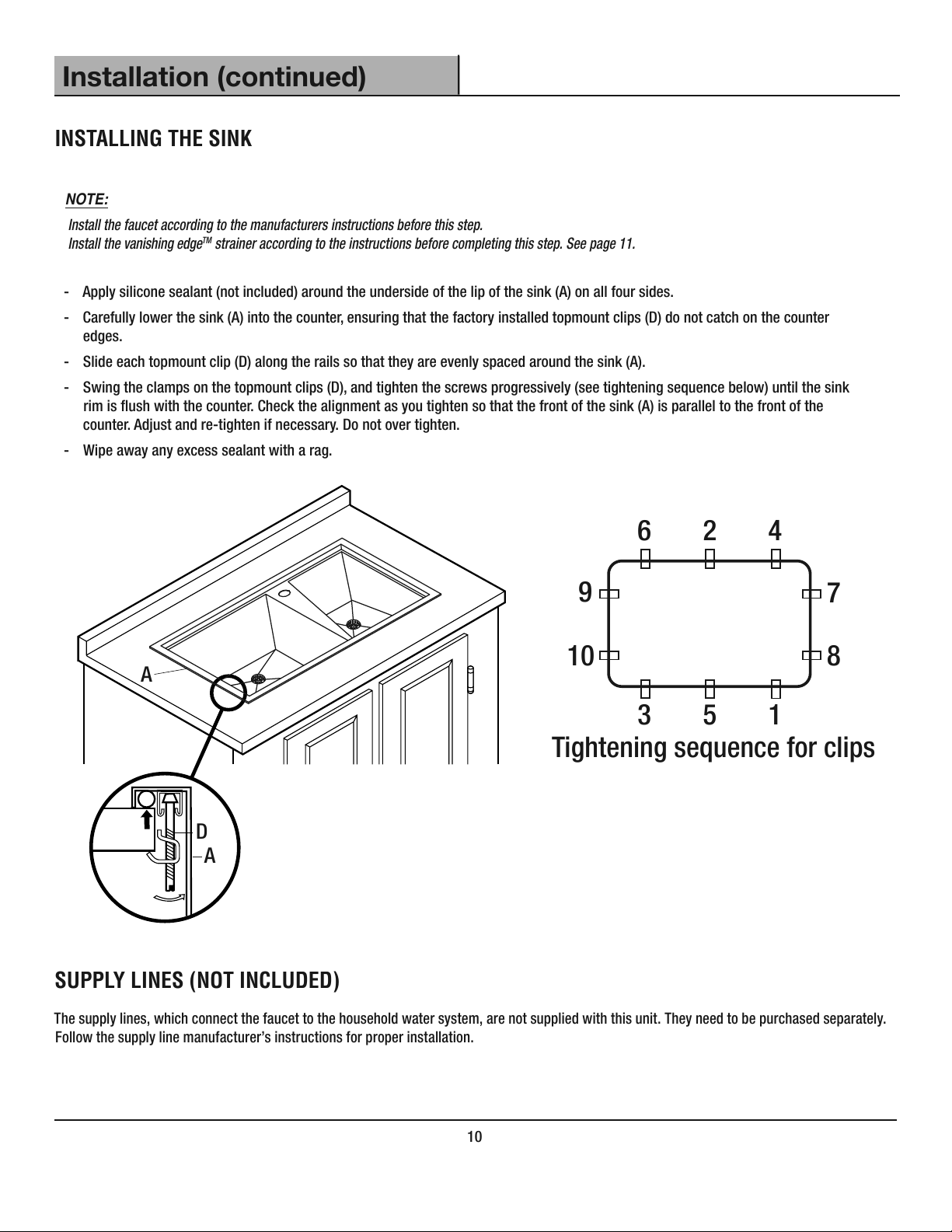
INSTALLING THE SINK
NOTE:
Install the faucet according to the manufacturers instructions before this step.
Install the vanishing edgeTM strainer according to the instructions before completing this step. See page 11.
- Apply silicone sealant (not included) around the underside of the lip of the sink (A) on all four sides.
- Carefully lower the sink (A) into the counter, ensuring that the factory installed topmount clips (D) do not catch on the counter
edges.
- Slide each topmount clip (D) along the rails so that they are evenly spaced around the sink (A).
- Swing the clamps on the topmount clips (D), and tighten the screws progressively (see tightening sequence below) until the sink
rim is ush with the counter. Check the alignment as you tighten so that the front of the sink (A) is parallel to the front of the
counter. Adjust and re-tighten if necessary. Do not over tighten.
- Wipe away any excess sealant with a rag.
9
6 2 4
3 5 1
7
810
Tightening sequence for clips
A
D
A
SUPPLY LINES (NOT INCLUDED)
The supply lines, which connect the faucet to the household water system, are not supplied with this unit. They need to be purchased separately.
Follow the supply line manufacturer’s instructions for proper installation.

11
CONGLOMKB.COM
Please contact customer.service@conglomkb.com or 1-877-333-0098 for further assistance.
Installation (continued)
INSTALLING THE VANISHING EDGETM STRAINER
B
C1
C2
C3
C4
C5
1
2
3
Not supplied
Not supplied
NOTE:
If you are installing a garbage disposer (not supplied), do not install the strainer.
You will need to purchase from Conglom Kitchen & Bath, an adaptor. This will replace
the ange from your garbage disposer.
Install the garbage disposer according to the manufacturer’s installation instructions
replacing the ange for the adaptor.
- Apply a small amount of plumber’s putty (not included) in the notch around
the drain hole of the sink.
- Connect the upper strainer body (C2) and the strainer ring (C3), and insert
them into the drain hole from the top of the sink.
- Connect the strainer gasket (C4) and lower strainer body (C5), and insert
them into the drain hole from underneath the sink.
- Insert the strainer screw (C1) through the entire assembly, from the upper
strainer body (C2) to the lower strainer body (C5). Tighten with a Phillips
screwdriver.
- Connect the plastic ange (1) and tail pipe (2), and thread the connecting
nut (3) through the tail pipe and ange up to the lower strainer body (D5).
Lock the connecting nut by hand.
NOTE:
The plastic ange (1), tail pipe (2), and connecting nut (3) are not supplied.
INSTALLING THE BOTTOM GRID
F
B
A
B
- Ensure that the vanishing edgeTM strainer basket (B) is already in the sink
(A) before placing the bottom grid (F).
- The bottom grid (F) must be positioned with its rubber supports down. Tilt
the grid up so it is at a slight angle, slide it into the sink (A), and place it
so that it is sitting at on the bottom of the sink.

12
Care and Cleaning
Your sink is manufactured with the highest grade stainless steel and will provide you many years of enjoyment with the proper care.
Do Do Not
- After use, always rinse your sink with tap water to
dilute and remove deposits.
- Towel dry the sink after use whenever possible
to prevent water spots. Should water spots occur,
clean with a mild solution of vinegar and water
followed by a thorough rinse.
- Use liquid soap, a general household cleaner, or
a weak solution of vinegar and water for regular
cleaning.
- Only use plastic scouring pads recommended for
use in stainless steel sinks, and only use them in
the bowl of the sink. Scrub in the direction of the
grain (original polish lines).
- Do not allow any food, detergent, soap or grease
to dry or sit for extended periods of time on the
surface of the sink.
- Never use abrasive cleaning products, as they will
dull and scratch the nish.
- Do not use scouring pads on the deck, as they will
dull the mirror nish.
- Never use steel wool pads, as they will leave iron
particles on the sink, which will cause corrosion.
- Never leave steel or cast iron pans in your
sink for extended periods of time, as this can
cause corrosion.

13
CONGLOMKB.COM
Please contact customer.service@conglomkb.com or 1-877-333-0098 for further assistance.
Service Parts
If you are missing parts or if you require replacement parts, please call our customer service team at customer.service@conglomkb.com or
1-877-333-0098, 8:30 am - 5 pm, EST Monday - Friday. Identify the required part(s) and have the part number(s) ready.
A
E
BC
D
Part Description Code Quantity
AVanishing edgeTM strainer QHS113 2
BStrainer assembly QHS155 2
CTopmount clip QHS138 10
DUndermount clip QHS109 10
EBottom grid QHS172 1

Retain this manual for future use.
Imported by:
St-Laurent, Québec, H4S 2C3
1-877-333-0098
customer[email protected]
www.conglomkb.com
Made in China
Table of contents
Other Presenza Kitchen Appliance manuals


