PRESONUS ACP88 User manual

ACP88
Eight Channel
Compressor/Limiter/Gate
User’s Manual
Version 1.2

ACP88
EIGHT CHANNEL
COMPRESSOR/LIMITER/GATE
USERSMANUAL
Version1.2
Copyright 1998,2000,2001 PreSonus Audio Electronics, Incorporated.
All rights reserved.

WARRANTY
PreSonus Limited Warranty
PreSonus Audio Electronics Inc. warrants this product to be free of defects in material and workmanship for a period of one
year from the date of original retail purchase. This warranty is enforceable only by the original retail purchaser. To be
protected by this warranty, the purchaser must complete and return the enclosed warranty card within 14 days of purchase.
During the warranty period PreSonus shall, at its sole and absolute option, either repair or replace, free of charge, any
product that proves to be defective on inspection by PreSonus or its authorized service representative. To obtain
warranty service, the purchaser must first call or write PreSonus at the address and telephone number printed below to
obtain a Return Authorization Number and instructions of where to return the unit for service. All inquiries must be
accompanied by a description of the problem. All authorized returns must be sent to the PreSonus repair facility postage
prepaid, insured and properly packaged. PreSonus reserves the right to update any unit returned for repair. PreSonus
reserves the right to change or improve the design of the product at any time without prior notice. This warranty does not
cover claims for damage due to abuse, neglect, alteration or attempted repair by unauthorized personnel, and is limited to
failures arising during normal use that are due to defects in material or workmanship in the product. Any implied
warranties, including implied warranties of merchantability and fitness for a particular purpose, are limited in duration to the
length of this limited warranty. Some states do not allow limitations on how long an implied warranty lasts, so the above
limitation may not apply to you. In no event will PreSonus be liable for incidental, consequential or other damages resulting
from the breach of any express or implied warranty, including, among other things, damage to property, damage based on
inconvenience or on loss of use of the product, and, to the extent permitted by law, damages for personal injury. Some
states do not allow the exclusion of limitation of incidental or consequential damages, so the above limitation or exclusion
may not apply to you. This warranty gives you specific legal rights, and you may also have other rights, which vary form
state to state. This warranty only applies to products sold and used in the United States of America. For warranty
information in all other countries please refer to your local distributor.
Limited Warranty Outside of The U.S.
PreSonus Audio Electronics products are warranted only in the country where purchased, through the authorized PreSonus
distributor in that country, against defects in material and workmanship. The specific period of this limited warranty shall be
that which is described to the original retail purchaser by the authorized PreSonus dealer or distributor at the time of
purchase. PreSonus does not, however, warrant its products against any and all defects: 1) arising Out of materials or
workmanship not provided or furnished by PreSonus, or 2) resulting from abnormal use of the product or use in violation of
instructions, or 3) in products repaired or serviced by other than authorized PreSonus repair facilities, or 4) in products with
removed or defaced serial numbers, or 5) in components or parts or products expressly warranted by another manufacturer.
PreSonus agrees, through the applicable authorized distributor, to repair or replace defects covered by this limited warranty
with parts or products of original or improved design, at its option in each respect, if the defective product is shipped prior to
the end of the warranty period to the designated authorized PreSonus warranty repair facility in the country where
purchased, or to the PreSonus factory in the U.S., in the original packaging or a replacement supplied by PreSonus, with
all transportation cost and full insurance paid each way by the purchaser or owner. All remedies and the measure of
damages are limited to the above services. It is possible that economic loss or injury to person or property may result from
the failure of the product; However, even if PreSonus has been advised of this possibility, this limited warranty does not
cover any such consequential or incidental damages. Some states or countries do not allow the limitations or exclusion of
incidental or consequential damages, so the above limitation may not apply to you. Any and all warranties, express or
implied, arising by law, course of dealing, course of performance, usage of trade, or otherwise, including but not limited to
implied warranties of merchantability and fitness for a particular purpose, are limited to a period of two years from either the
date of original retail purchase or, in the event no proof of purchase date is available, the date of manufacture. Some states
or countries do not allow limitations on how long an implied warranty last, so the above limitations may not apply to you.
This limited warranty gives you specific legal rights, and you may also have other rights which vary from state to state,
country to country.
PreSonus Audio Electronics, Inc.
7257 Florida Blvd.
Baton Rouge, LA 70806
(225) 216-7887
Copyright 1998, 2000, 2001 PreSonus Audio Electronics, Incorporated. All rights reserved.

TABLE OF CONTENTS
1Overview
1.1 Introduction
1.2 Features
2 Controls&Connections
2.1 Front Panel Basic Layout
2.2 Compressor Controls
2.3 Gate Controls
2.4 Gain
2.5 Bypass & Link
2.6 Patch Panel
2.7 Power
3BasicSetupandApplications
3.1 Some Basic Patching
3.2 Basic Applications
4Technical
4.1 Specifications
4.2 Block Diagram

OVERVIEW
5
1.1 INTRODUCTION
Thank you for purchasing the PreSonus ACP-88 multi-channel
dynamics processor. Your processor was designed using state of the art
components to deliver crystal clear compression and noise gating for an infinite
period of time. We believe the ACP-88 to be an exceptional sounding unit and
an exceptional value. Feel free to contact us at 1-800-750-0323 anytime for
any reason. We value your suggestions and your comments. PreSonus
Audio Electronics is committed to constant product improvement and feel the
best way to accomplish this task is by listening to the experts on our gear, our
valued customers. We appreciate the support you have shown us through the
purchase of our products.
Please pay close attention to how you connect your ACP-88 to your system.
Improper grounding is the most common cause of noise problems found in
studio or live sound systems. We urge you to scan this manual before hooking
up your ACP-88 to become familiar with its features and various applications.
Good luck and enjoy your ACP-88!
1.2 FEATURES
The following is a summary of your ACP-88’s features:
?Eight Compressors/Limiters. Each channel of your ACP-88
contains an audio Compressor that can also be setup as a
Limiter by varying the ratio of compression. You have broad
control over Threshold, Ratio, Attack and Release for each
processor. You can select betweenAuto orManual Attack and
Release curves and Hard or Soft Knee compression types
(refer to the application section of this manual for a quick tutorial on
compression/limiting). The Compressor will prove to be very
useful in many situations such as recording instruments or vocals
that vary in loudness, or setting it up as a limiting device before
your digital recorder to prevent distorting your digital recorder’s
inputs. Live sound system processing is another great application
where your ACP-88 can really take control.
?Eight Dynamic Noise Gates.Each channel of your ACP-88 has
a separate dynamic noise gate that can be used to Gate an entire

OVERVIEW
6
drum kit, clean up a noisy tape machine, isolate an instrument or
separate a vocal from background noise. Each noise Gate
provides control over Attack, Threshold, Release and Gate
close Range. The Gate close range can be useful in creating a
more natural sounding blend or mix when gating many instruments
at once.
?Comprehensive Channel Linking. Using the Link function
allows you to combine any combination of ACP-88 channels
effectively forming a subgroup. When linked, all processors follow
the setting of the Masterprocessorwhich isalwaysthe processor
furthest to the Left in a Link group. For example, you could Link
together channels 7and 8to form a Stereo pair, channels 3, 4
and 5to form a subgroupof processors, while channels1, 2and
6remain available for independent applications such as
compression, limiting,or gatingas the situation dictates.
?Separate Bypass and Gain for Every Channel.Each Channel
has a separate Bypass for auditioning a signal ‘before and after’
processing with the compressor, limiter, or the Gate and a Gain
control to make up any loss in signal level resulting from the
amount of compression being applied.
?Compressor Sidechain Jack on Every Channel. Each
channel of your ACP-88 was designed with a special jack for
spectral processing, compression keying and ducking
applications. Sidechaining is useful for removing annoying
sibilance from vocal tracks (de-essing) or automatically ducking
tracks behind a narrator for ‘auto mixing” a service, broadcast or
performance. When multiple channels are Linked together, the
Send of the Sidechain jack of the Master channel contains a
mix of all the channels in the Link: a very cool feature allowing
control over multiple channels of processing with one Sidechain
send/return. (See the section on Sidechaining for application
notes.)

OVERVIEW
7
?Separate Gate Sidechain/keying Jacks for Each Channel.
Your ACP-88 also includes a separate jack on each channel for
Gate sidechain/Keying. This is useful for synching an external
sound to a snare track, for example, or putting equalizers or filters
before the Gate key to enable Gatingonly the lower frequency of
a kick drum, etc.
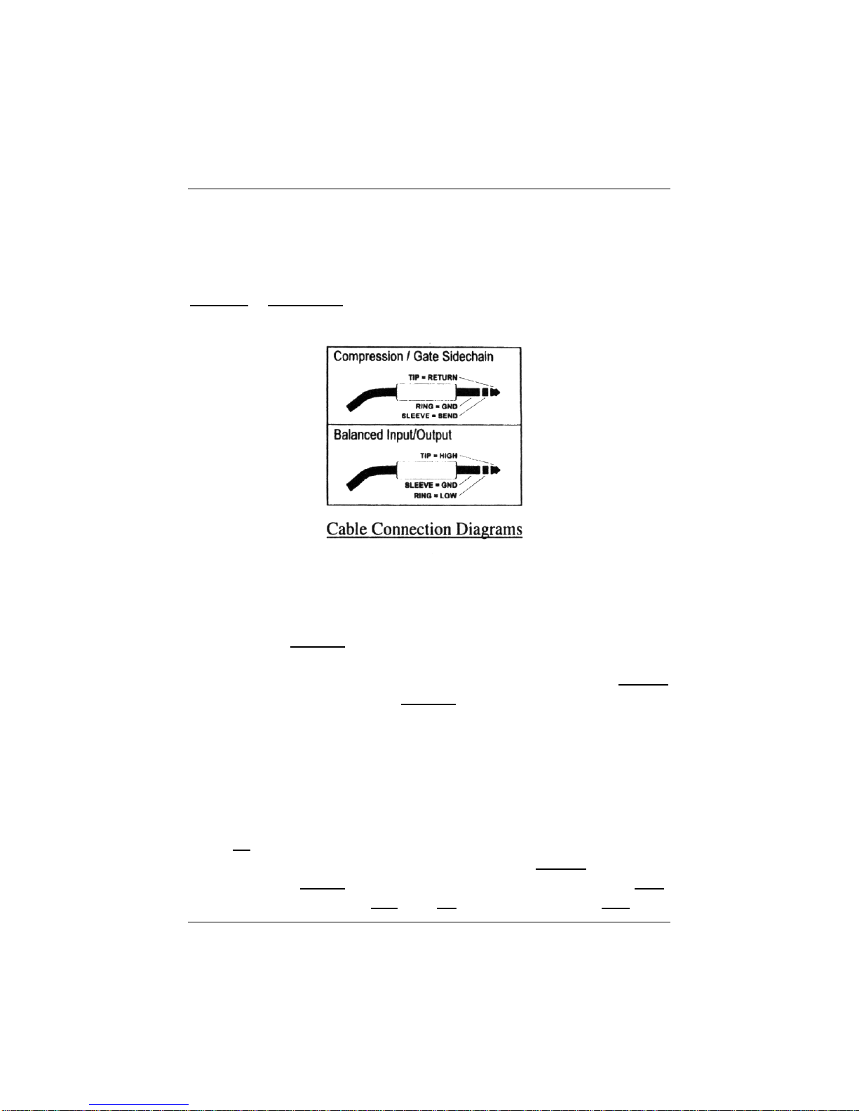
?Balanced/Unbalanced Inputs and Outputs. Your Acp-88
accepts either balanced or unbalanced inputs and outputs using
tip-ring-sleeve(TRS) connectors.
?+ 4dBu or –10dBV. The internal operating level of your ACP-88
can be switched between +4dBu (pro levels) to –10dBV (line
levels), making it possible to use in virtually any application.

OVERVIEW
8
To Get Help…
Call Us: 1-800-750-0323, 9 AM to 5 PM, CST
Visit ourWorld Wide Web Site: http://www.presonus.com
CONTROLS & CONNECTIONS
9
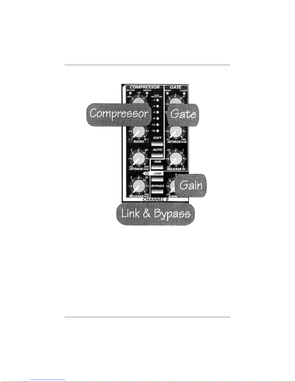
2.1 Front Panel Basic Layout
Notice that the front panel is divided into eight identical sections.
These are the eight signal processing chains of the ACP-88.
Each channel contains:
?Compressor/Limiter
?Noise Gate
?Gain Makeup
?Link & Bypass Control
CONTROLS & CONNECTIONS
10
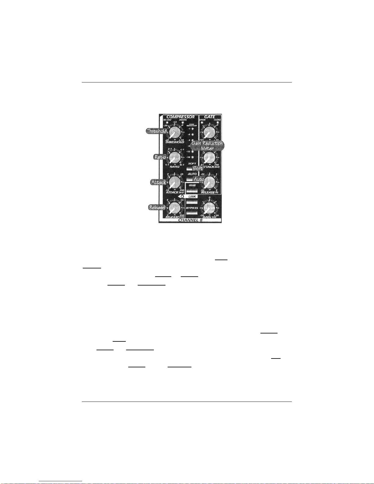
2.2 Compressor Controls
Threshold
The Compressor Threshold sets the level at which compression
begins. The belowand above LED’s over the Threshold knob indicate
whether the input signal is below or above the Threshold setting. When the
signal is above the Threshold setting, it becomes ‘eligible’ for compression.
Basically, as you turn the Threshold knob counter-clockwise, the input signal
is compressed. (If you have a ratio setting of greater than 1:1.)
Ratio
Ratio sets the compression slope. This is defined as the output level
versus the inputlevel. For example, if you have theRatio set to2:1, any signal
level above the Threshold setting will be compressed at a compression ratio
of 2:1. This simple means that that for every 1dB of level increase into the
compressor, the outputwill onlyincrease½ dB, thus producing a compression
Gain reduction of 0.5 db. As you increase the Ratio, the compressor
gradually becomes a limiter. A limiter is defined as a processor that limits the
level of signal to the setting of the Threshold. For example, if you have the

CONTROLS & CONNECTIONS
11
Threshold knob set at 0 dB, and the Ratio turned fully clockwise, the
Compressor becomes a Limiterat 0 dB. This means the signal will belimited
to an output of0 dBregardless of the input signal.
Attack
Attacksets the speed at which the compressor ‘acts’ on theinput
signal. Aslow attack time (fully clockwise) allows the beginning envelope of a
signal (commonly referred to as the initialtransient) to pass through the
compressor uncompressed, whereas afastattacktime (fully
counterclockwise) immediatelysubjects the signal to theRatio and
Thresholdsettings of the compressor.
The Attack control is only active when the Auto button isnot
pushed in. When the Auto button is pushedin, the compressor
automatically determines the appropriate Attack time for compression.
Release
Releasesets thelengthof time the compressor takes to return the
Gain reductionback tozero(no gain reduction). Veryshort Release times
can produce a very choppy or ‘jittery’ sound, especially in low frequency
instruments such as bass guitar. Verylong Releasetimes can result in an
overly compressed signal, sometimes referred to as ‘squashing’ the sound. All
ranges ofRelease can be useful at different times however and you should
experiment to become familiar with the different sound possibilities. (Refer to
the applicationssection of this manual for some ideas.)
The Release control is onlyactivewhen the Auto button
is not pushed in. When the Auto button is pushed in, the compressor
automatically determines the appropriate Release time for
compression.

CONTROLS & CONNECTIONS
12
Soft
The Softbutton selectsSoft KneeandHard Kneecompression
curves. When this button is pushedin, Soft kneecompression curves are
used, otherwisehard knee compression curves are used. WithHard knee
compression, the gainreduction applied to the signal occursas soon as the
signal exceedsthe level set by the threshold. WithSoft knee compression, the
onsetof gain reduction occurs graduallyafterthe signal hasexceededthe
Threshold, producing a more musical response (tosome folks).
Auto
When pushed in, the Auto button places the compressor in
automatic attack and release mode. The Attack and Release knobs
become inoperative and a pre-programmed Attack and Release
curve is used.

CONTROLS & CONNECTIONS
13
2.3 Gate Controls
Attack
The Gate attack control sets the speed at which the gate opens to
allow signal to pass through it. This control is variable from10microseconds to
100milliseconds. It is advisable to use slower Attacktimes when gating vocals
or quieter instruments to avoid what is often described as gate ‘clicking’. This
phenomena is not made by a mechanical device in the noise gate, but is rather,
an audible manifestation of ‘no signal’ to the presence of signal as the gate
opens. The fastest setting is fully counter-clockwise(left) to the slowest setting
all the way round to the right (clock-wise).
Threshold
The gate Threshold sets the level at which the gate opens as
indicated by the ‘OPEN’ LED above the Threshold knob. Essentially, all
signals above the Thresholdsetting are passed through unaffected, whereas

CONTROLS & CONNECTIONS
14
signals below the Threshold setting are reducedin level by the amount set by
the Range switch. The ‘CLOSE’ LED above the Threshold knob indicates
when the gate is closed (the signal level is below the threshold). If the
Threshold is set fully counter-clockwise, the Gate is turned off(always open),
allowing all signals to pass through unaffected.
Release
The Gate Release time determines the rate at which the gate closes.
This is indicated by observing the OPEN and CLOSED LED’s. As the
Release time is lengthened (clockwise), you will notice that the CLOSE LED
reflects the close time. Releasetimes should typically be set so that the natural
decay of the instrument or vocal being gated is not affected. Shorter Release
times help to clean up the noise in a signal but may cause ‘chattering’ in
percussive instruments. Longer release times usually eliminate ‘chattering’ and
should be set by listening carefully for the most natural sounding Release for
the signal being processed.
Range Switch
The Gate range is the signal level reduction that occurs when the
gate closes. Therefore, if the Range switch is set at 15 dB, there will be a
slightchange in the signal as it crosses theThreshold. If theRange switch
is pushed in, the signal will be Gated (reduced) by 60 dB. The CLOSE LED
above the Thresholdknob indicates this by changing brightness relative to the
Range amount that has been selected. When the Range is set to 15 dB, the
CLOSE LED will show half illumination. When the Range is set to 60 dB, the
CLOSE LED will illuminate to it’s brightest level at the end of the release time.
(REMEMBER: Releasetime is set by theReleasecontrol.)

CONTROLS & CONNECTIONS
15
2.4 Gain
Gain
When compressing a signal, Gain reduction usually results in an
overall reduction of level. The Gain control allows you to restore the loss in
level which occurs due to the amount of compression used. (like readjusting the
volume.)
2.5 Bypass & Link
Bypass
Activating the Bypass effectively removes all processing being
performed by your ACP-88 and returns the signal tounity gain. You should use
Bypass often when setting up your ACP-88 to compare the ‘before and after’
results of the signal processing effecting your audio signal. Bypass affects
both the Gate and the Compressor. When Bypassed, the Link function is
interrupted for that channel and essentially breaks the link in your linking ‘chain’.
Link
When the Link button is engaged (pushed in) the LED labeled LINK
becomes active indicating this channel has become theslaveofthe channel to
its immediate left (The Link LEDis onlyactivewhen the signal is present in the
Linked channel). All of the controls for the Linked channel become disabled
and metering occurs by way of the Gain reduction meter of the channel to
the left (Exception: the LED meter of the Slaved channel is still useful to
indicate the presence or lack of signal). Essentially, the left channel is still the
Master and the channel with the Link button pushed in is the Slavechannel in
a stereo linked pair. If multiple Link buttons are pushed in, then the channel
farthest to the leftof the multipleLinked channels (without its link button pushed
in) becomes the Master for the multiple Linked channels. In this case, all
metering should be referred to theMasterchannel’s meter.
IMPORTANT: When a channel is Linked (link button pushed in),
all of it’s controls are inactive. The Link LED is active. Also, even
though the meters on the Linked channel are still operational
CONTROLS & CONNECTIONS
16
(presence or lack of signal), all metering should be referred to the
Master channel’s meter for the Gain reduction level of the Linked
channels!
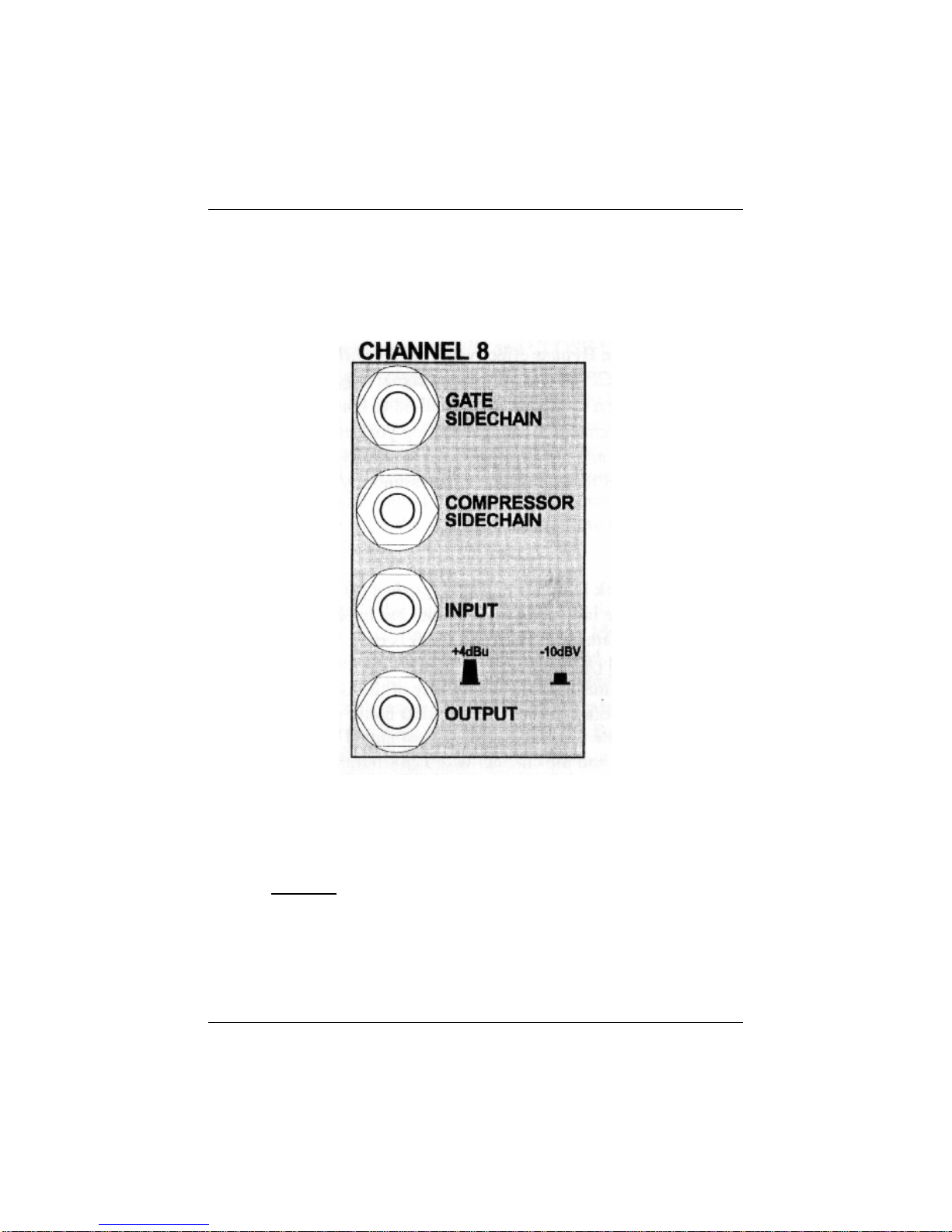
2.6 Patch Panel (Back)
Input
The Inputjack accepts balanced tip-ring-sleeve or unbalanced tip-
sleeve connectors. TheInput canhandle up to+24dBu unbalanced or up to
+18dBu balancedsignal levels.
CONTROLS & CONNECTIONS
17
Output
The output jack accepts balanced tip-ring-sleeve or unbalanced tip-
sleeve connectors. The output will deliver up to +24 dBu in signal level,
balancedor unbalanced.
+4/-10 Switch
This switch adjusts the internal operating level of your ACP-88 when it
is connected to line level (0 dB = -10 dBV) gear. With this switch in the ‘-10’
position, the signal is adjusted by 11.2 dB so that it can be processed at the
lower noise floor of your ACP-88’s internal circuitry. The signal level islowered
on the way out to match with your line level gear’s input. When the switch is in
the ‘+4’position, the signal is not changed since this matches the optimum
internal operating level of your ACP-88.
Compressor Sidechain
The Sidechain jack on each channel interrupts the signal that the
compressor is using to determine the amount of Gain reduction to apply.
When no connector is inserted into this jack, the input signal goes directly to
the compressor’s control circuitry. When a connector is inserted into this jack,
the signal path is broken. If you have inserted a ¼ inch tip-ring-sleeve (TRS)
connector, the input signal is sent back out of the ACP-88 via the ring of the
CONTROLS & CONNECTIONS
18
connector. This signal can then be processed by an equalizer for example to
reduce sibilance 9de-essing) in a vocal track. The signal is thenreturnedto the
unit via the tip of the connector. The signal sent via the ring could be that of a
narrator or vocalist. In this application, the audio that you are passing through
the compressor will automatically ‘duck’ when the narrator speaks or vocalist
sings.
Gate Sidechain/Key Insert
The Gate sidechain jack accepts a tip-ring-sleeve connector and is
used to open the Gate from either a modified version of the signal passing
through the Gate or some other external source. For example, the Gate may
be Keyed from a version of the kick drum’s signal with all of the high
frequencies rolled off. This set-up could be useful to stop the kick drum’s gate
from opening during a cymbal crash, for example.
NOTE: The Key and Sidechain are in the signal path of the gate and
compressor, respectively. These inserts require periodic cleaning as you
would a patchbay to insure proper operation. It is not uncommon for
condensation to form a film on these contact points. Failure to clean these
inserts can result in a loss or degradation of signal. Should a gate or
compressor fail, inserting a ¼ inch connector several times into the insert
points commonly restores normal operation.
CONTROLS & CONNECTIONS
19
2.7 Power
Power Connection
The power jack on your ACP-88 accepts a standard IEC cord like
those found on most computers and professional recorders. Your ACP-88
contains a custom built; internal power supply, no wall wart. This way you can
be assured of clean power and rugged construction that will last!
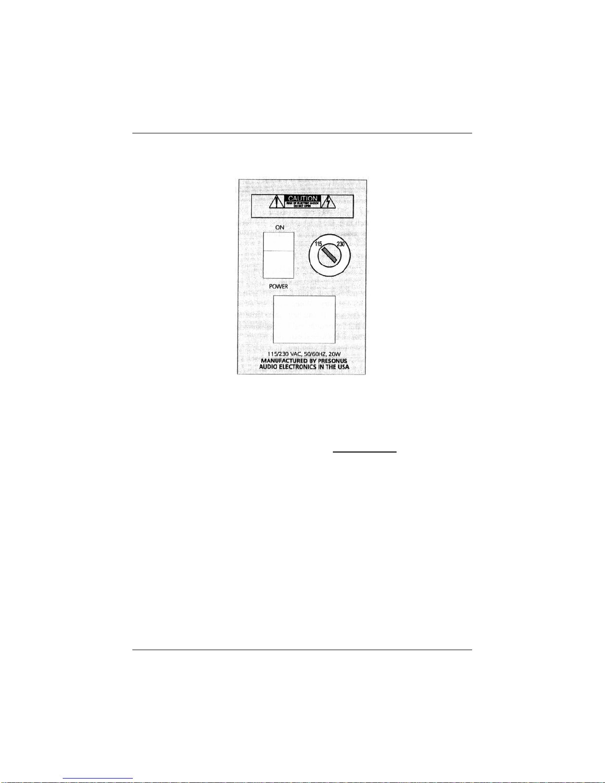
Power Selection
Before powering up your ACP-88 for the first time, be sure to check
the position of the power selector switch on the back of the unit. Make
certain that the power voltage level selected matches that of your country’s
correct power requirements. The arrow on the outside ring of the power
selector switch should be aligned with the appropriate voltage. This can be
accomplished by inserting a small screwdriver into the slot on the power
selector switch and aligning the correct setting beneath the arrow on the
outside ring of the power selector switch.
Power Switchl=ON 0=OFF. (hmmm….)

BASIC SETUP & APPLICATIONS
3.1 Some Basic Patching
Inserting into your mixers insert points
Other manuals for ACP88
2
Table of contents
Other PRESONUS Computer Hardware manuals


