16 1716 17
Owner’s ManualPreSonus StudioLive™16.0.2
Quick Start:
Level
Setting
Quick Start:
Level
Setting
Overview
Overview
Hook-up
Hook-up
Connecting
to a
Computer
Connecting
to a
Computer
Tutorials
Tutorials
Technical
Information
Technical
Information
Trouble-
shooting
& Warranty
Trouble-
shooting
& Warranty
Scenes, Presets, System Menu,
and MIDI Control
Scenes, Presets, System Menu,
and MIDI Control
Software: Universal Control,
SL Remote, Capture,
& Studio One Artist
Software: Universal Control,
SL Remote, Capture,
& Studio One Artist
Controls 44 Controls
Controls
Controls
16 17
4.1 The Fat Channel The Fat Channel 4.1
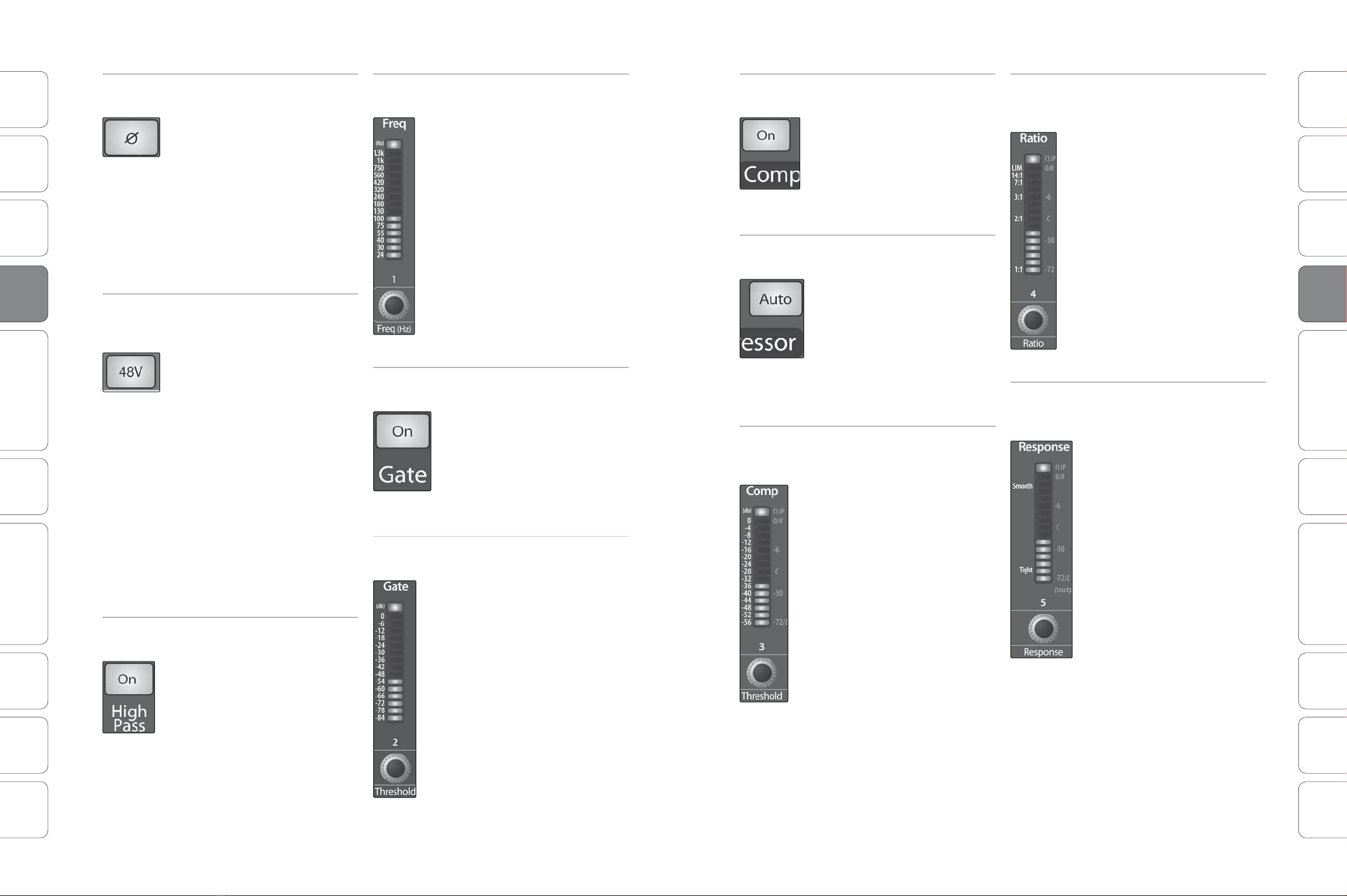
High Pass
Filter
Adjusts the High Pass Filter’s Cut-off
Frequency.
The High Pass Filter section
consists of an encoder and a meter.
You will notice that the there is a
frequency range to the left of the
meter. The high-pass lter’s cuto
frequency can be set from 24 Hzto
1 kHz.
Remember that all frequencies
below a high-pass lter’s cuto
frequency are attenuated. See
Section 8.3.1 for more details.
The slope of the High Pass Filter is
-6 dB/octave.
Gate On/O
Button
Turns the Gate On and Off for the
Selected Channel.
This button engages and
disengages the gate for the
selected channel. It will illuminate
to indicate that the gate has been
enabled.
The gate is available for all
input and output buses.
Gate
Threshold
Sets and Displays the Threshold of the
Gate for the Selected Channel.
This encoder sets, and the meter
displays, the gate threshold for the
selected channel. The threshold
determines the level at which the
gate will open. Essentially, all
signals above the threshold setting
are passed through unaected.
You can set the threshold from 0to
-56 dB.
Compressor
On/O
Turns the Compressor On and Off for
the Selected Channel or Output Bus.
This button engages or disengages
the compressor for the selected
channel or output bus. It will
illuminate to indicate that the
compressor has been enabled.
The compressor is available for all input and
output buses.
Auto Mode
Button
Enables Automatic Response Mode
When Auto mode is active, the
Response control becomes
inoperative, and a preprogrammed
attack and release curve is used. In
this mode, the attack is set to 10
ms, and the release is set to 150
ms. All other compressor
parameters can still be adjusted
manually.
Compressor
Threshold
Sets and Displays the Threshold of the
Compressor for the Selected Channel
or Output Bus.
This encoder sets, and the meter
displays, the compressor threshold
for the selected channel or output
bus. When the signal’s amplitude
(level) exceeds the threshold
setting, the compressor engages.
Turning the knob counterclockwise
lowers the threshold so that
compression begins at a lower
amplitude. The threshold can be
set from -56 to 0dB.
Compression
Ratio
Sets and Displays the Compression
Ratio for the Selected Input Channel
or Output Bus.
This encoder sets, and the meter
displays, the compression ratio (or
slope) for the selected channel or
output bus. The ratio sets the
compression slope, which is a
function of the output level versus
the input level. For example, if you
have the ratio set to 2:1, any signal
levels above the threshold setting
will be compressed at a ratio of 2:1.
This means that for every 2dB of
level increase above the threshold,
the compressor’s output will only
increase 1 dB. The ratio can be set
from 1:1 to 14:1.
Compressor
Response
Sets and Displays the Compressor
Attack Setting for the Selected Input
Channel or Output Bus.
This encoder sets, and the meter
displays, the compressor’s
response setting for the selected
channel or output bus. The
Response control sets the attack
and release tapers for the
Compressor simultaneously. A
tight response time triggers the
compressor immediately and
returns the gain reduction back to
zero quickly when the signal drops
below the compressor threshold.
Asmooth response time allows the
beginning component of the
signal or“initial transient” to pass
through, uncompressed and
extends the time of length of time
before the gain reduction returns
to zero.
Power User Tip: In general, a tighter response
time should be used for instruments with
relatively few transients, like drums and
percussion, while a smooth setting should be
using for instrument with a lot of transients,
like vocals and strings.
Phase Reverse
Button
Reverses the Phase of the Selected
Channel.
Push this button to invert the
phase of the selected channel’s
signal (that is, to alter the phase by
180°). The button will illuminate,
indicating that Phase Reverse is
active. The Phase Reverse button
can be used to correct audio
signals that are out of phase and
cancelling/reinforcing each other.
Phase reverse is only available on the 16
channels of the input bus.
48V Button Engages Phantom Power in the
Microphone Preamp of the Selected
Channel.
Push this button to engage
phantom power in the selected
channel’s microphone preamp. The
button will illuminate, indicating
that phantom power is active.
Phantom power transmits 48Vof
DCelectric power through a
microphone cable. Most
commonly it is used to power
condenser microphones, although
some direct boxes also take
advantage of it. For more
information on microphones,
please consult the microphone
tutorial in Section 8.1.
Phantom power is only available on the 12
microphone preamps of the input bus.
High Pass
Filter On/O
Turns the High Pass Filter On and Off
fo the Selected Channelor Output Bus.
This button engages or disengages
the high-pass lter for the selected
channel or output bus. It will
illuminate to indicate that the
compressor has been enabled.
The high-pass lter is available on the 16
channels of the input bus, the 4 Auxes, and
both internal FX buses.


