Made By: Pressure Products -9600 NCR 5 - Wellington, Co. 80549 - 970-416-7351
Thank You for choosing a Foot Faucet. Please read instructions completely before starting to install the Foot
Faucet. The Foot Faucet is intended to be installed by a qualified person to ensure proper water and electrical
connections.
Foot Faucet Kit
Your Foot Faucet kit includes;
•1- set of foot levers
•2- valves with 3/8” compression fittings
•1- control box
•mounting hardware
Overview of Foot Faucet
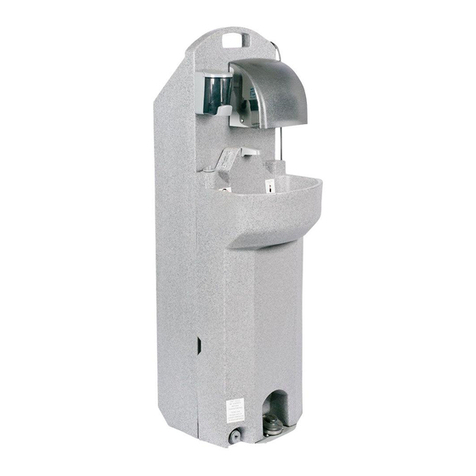
This is a picture of a typical installation of the Foot Faucet system. TURN OFF
WATER SUPPLY VALVES. Mount pedal assembly to underside of cabinet
with ¼” (supplied) bolts, drill a ½” hole in the floor of the cabinet for the
control cable, then cut out a 3.25” section of each water supply tube (or use a
threaded hose fitting) and place the Foot Faucet valves in-line (valve must
point correct direction). That’s all there is to it!
The components are plugged into the control box and the water valves are
turned back on.
The Foot Faucet gets power from the outlet for the garbage disposal, so in
order to make the Foot Faucet work, turn on your garbage disposal wall switch
then turn on the water faucets to full blast, then push the levers. Leave the wall
switch and knobs (lever) for hot and cold water in “on” positions.
Detailed Instructions for Foot Faucet Installation
1. TURN
OFF
WATER
SUPPLY
VALVES.
2. Mount pedal assembly to the underside of the cabinet floor with included hardware. Shims can be
used to get the levers closer to the floor, the levers can be ground shorter with a bench grinder (or a
hand file) if they scrape on the floor. Measure the depth of the toe space in the cabinet and drill a ½”
hole in the floor of the cabinet for the plug to pass through.
3. There are options for this. (a) Cut out a 3.25” section from each water supply tube
and place Foot Faucet valves in-line. (b) Get Threaded hose with 3/8” compression end
for the Foot Faucet valve and use just the threaded part of the supplied fitting. (c) Your
particular arrangement may require additional hardware.
Be sure valve is pointing the correct direction. The arrow on the valve should point in
the direction of water flow.
1/4” to 3/4”
clearance to
floor.
__
3.25”
__
