5
6.1. Servicing the LW-351
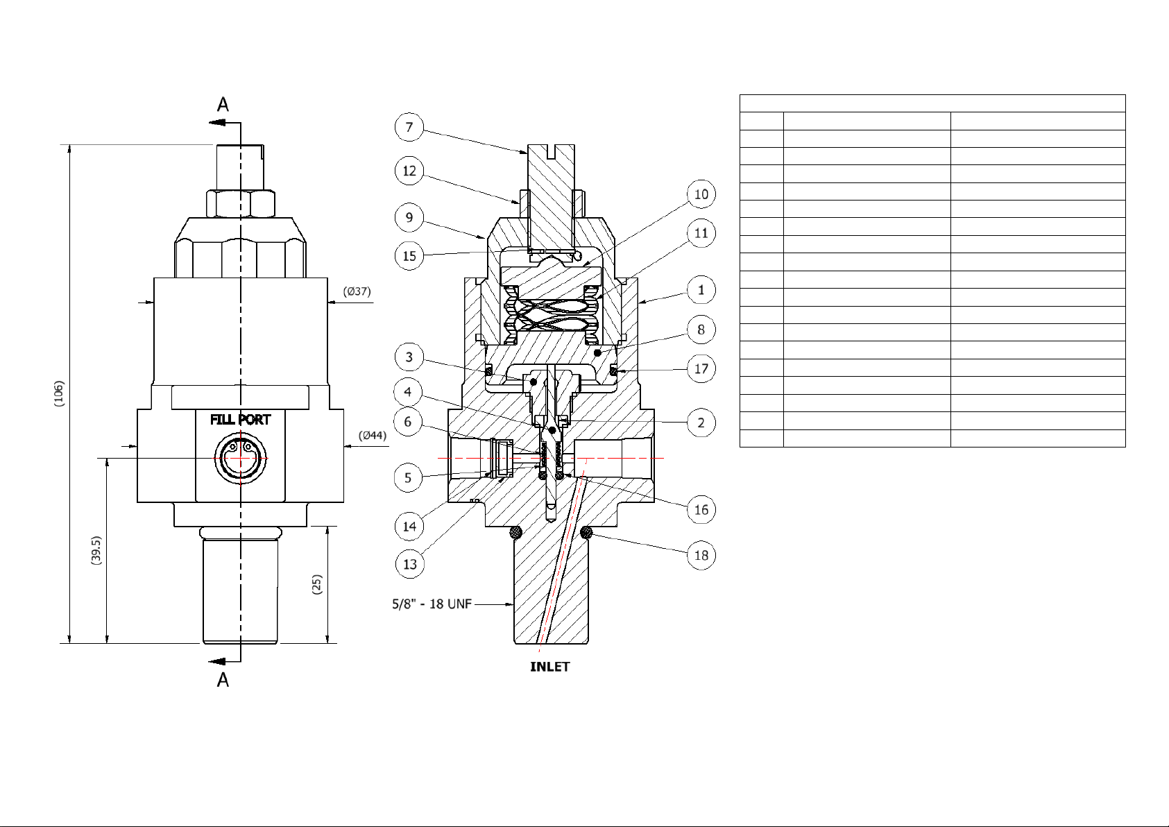
*Note: fig 1 should be used as a reference for the following set of instructions
6.1.1. Accessing the Main Valve Assembly
To access the Main Valve Assembly (MVA):
i. With the flats of the Regulator Body (1) secured in a vice, ensuring that the
Adjusting Screw (7) is fully wound anti-clockwise (*Ref. 6.1.2), loosen and
remove the Bonnet Assembly (7, 9, 12, 15) using a 27mm wrench
ii. Remove the Upper Spring Rest (10) and Load Spring (11)
iii. Using needle nosed pliers, remove the sensor assembly (8,17)
iv. The Solid Disk Seat (3) and Soft Seat (2) can then be removed using a 12mm
socket.
v. Visually inspect the Solid Disk Seat (3) and soft seat (2) for any potential damage
under a microscope
*Note: As the seat is a compression fit, it is likely that the soft seat will be secure
in the Solid Disk Seat. As such it is always recommended to replace both the
parts during service, where necessary.
vi. Remove the Main Valve (4) and Main Valve Spring (6) from the regulator body (1)
vii. Visually inspect the Main Valve (4) for any potential damage under a microscope
viii. Remove and replace the main valve O-Ring (16)
ix. Replace the Main Valve Spring (6) and Main Valve (4) and place into the
Regulator Body (1)
x. Guide the Solid Disk Seat (3) and Soft Seat (2), over the stem of the Main Valve
(4) taking care not to damage its sealing face against the tip of the valve.
xi. Screw the Solid Disk Seat (3) into the regulator body (1) and tighten to 4.5Nm,
using a 12mm socket
xii. Replace the O-ring (17) from around the sensor (8), then place the sensor
assembly (8,17), into the Regulator Body (1)
xiii. Position the Load Spring (11) around the top of sensor (8) and place the Upper
Spring Rest (10) on the to the assembly
xiv. Screw the Bonnet assembly (7, 9, 12, 15) into the Regulator Body (1) and using a
torque wrench with a 27mm open ended attachment, tighten to 15Nm
It is recommended that all parts in the repair kits are used. Any defect parts removed during
the service should be disposed of. Parts should be kept clean in line with media
requirements. Following re-assembly of the regulator, pressure tests should be made to
both the inlet and outlet side of the regulator, to ensure there is no internal or external
leakage across the regulator.
To ensure that the main valve assembly has been correctly and effectively installed it may
be required to perform the appropriate seat leak test as per ANSI/FCI 70-2.