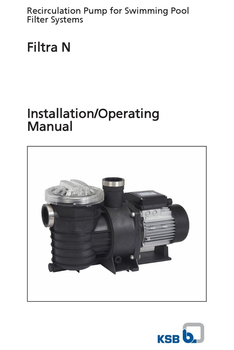
Pressure Tech Turret Series User manual

PressureTech Turret Series
High Pressure Coolant Pumps
Models: EU-1000, EU-1000-2
PressureTech
Perfection Under Pressure
New England Tool Corp.
161 Sanrico Drive
Manchester, CT 06042
MAINTENANCE MANUAL
EU-1000-2
EU-1000

Table of Contents
Safety Instructions ................................................................................................. pg. 3
Operation ................................................................................................. pg. 4
Maintenance Schedule ................................................................................................. pg. 6
Electrical Diagram ................................................................................................. pg. 7
Sheet Metal Assembly ................................................................................................. pg. 8
Motor Assembly ................................................................................................. pg. 10
Valve Assembly ................................................................................................. pg. 11
Left Filter Assembly ................................................................................................. pg. 12
Right Filter Assembly ................................................................................................. pg. 13
Maintenance Manual for EU-1000 & EU-1000-2

• Make sure electrical power is disconnected before servicing pressure pump or electrical
cabinet.
• Do not move high pressure pump while it is powered on.
• For maintenance purposes, only use parts provided or recommended by PressureTech and
New England Tool Corporation.
• In case of emergency press the E-STOP (Emergency Stop) button on the CNC machine and
disconnect power by shutting OFF the main circuit breaker (CBI) on the high pressure pump.
• Allow only qualified personnel to handle and service your high pressure pump system.
• Make sure high pressure pump is not making any erratic (unusual) noise during operation, and
inspect for any signs of leakage around pump area.
• lnspect hydraulic hoses for tightness and leaks. Make sure that the filter vessel cover is latched
and secure.
• Take extra precaution if you run high pressure pump and machine unatended. Fire hazard may
exist during operation of the machine and pump. This is especially true if you are in the process
of machining materials such as Magnesium, Titanium, etc.
• We recommend installing a fire suppression system inside the machine, especially if the
machine is running unattended.
• Your high pressure pump system is not provided with a coolant flow switch. The system relies
on the machines coolant level alarm to ensure pump is not running dry without coolant oil or
fluid.
• Always ensure that there is enough oil in the machine, oil reservoir and high pressure pump
filter vessel. Refill the oil tank as necessary.
• Prevent oil or water from coming into contact with electrical equipment.
• Under no circumstances should you ever come into contact with high pressure coolant streams.
• Never install shut-off valves between the pump and discharge pressure regulator, or in the
regulator bypass line.
SAFETY INSTRUCTIONS
Page 3Maintenance Manual for EU-1000 & EU-1000-2

FILTER SYSTEM START-UP PROCEDURE
Prior to turning on the flow to the inlet service, please make the following checks:
1. Check inside filter unit to be sure basket and filter bag (if applicable) are in housing and do not require
cleaning or replacement. If necessary install a clean filter basket and bag (if applicable).
2. Check that filter unit cover is securely fastened to housing. You are now ready to open the flow to the inlet
service line. Slowly open the inlet service line approximately 25% of normal operational flow (open slowly
so as not to displace filter bag inside the housing). After filter unit is pressurized and vented, slowly open
outlet service line unit valve until completely open. Complete opening of inlet service line until desired flow
rate is reached.
Once the desired service flow has been established, the filter will operate efficiently until dirty. However,
under no circumstances should more than 5 PSI differential pressure through the filter be obtained.
Operating the filter unit with a high differential may cause filter bags to rupture and/or cause damage to filter
system and downstream equipment.
To prevent excessive drop through the filter unit, regular inspection of the filter media is required. Monitoring
of differential pressure through the housing can be utilized as a means of determining whether or not the
filter media needs cleaning or replacement.
MAINTENANCE
When it becomes necessary to clean or replace filter media, follow the procedure outlined below:
1. First close the flow from the inlet service line.
2. Close the flow to the outlet service line. (In some applications closing flow to outlet is not required.)
3. Relieve the pressure from the filter unit.
OPERATION
WARNING
CONTENTS UNDER PRESSURE
Relieve Pressure in accordance
with Manufacturer’s instructions
before opening the Filter Vessel.
FAILURE TO DO SO MAY RESULT
IN SERIOUS BODILY INJURY.
Page 4Maintenance Manual for EU-1000 & EU-1000-2

4. Drain housing sufficiently to access filter basket.
5. Remove cover by loosening the T-bolt clamp sufficiently to allow removal of the clamp assembly.
6. Remove filter basket and clean thoroughly, remove the filter bag (if applicable) and throw away. (Cleaning
and reusing the filter bag is not recommended.)
7. Remove debris and sludge from inside the inlet portion of housing to avoid interference with flow of fluid
being filtered.
8. Install clean filter basket and filter bag (if applicable). Place the basket into the filter housing,
make sure the basket flange is firmly seated onto the step on the inside of the housing. Insert
bag into the bag basket making sure filter bag ring is firmly seated against the top of the basket
flange. For best results, be sure filter bag is installed fully extended to the bottom of the basket.
9. Inspect cover gasket for cuts or other signs of failure and make sure it is properly seated. Your
PressureTech Turret Series unit is now ready for operation. Refer to filter system
start-up procedure.
SPARE PARTS (FOR MAINTENANCE)
Your PressureTech Turret Series unit will give you many years of reliable service provided periodic
inspections are made of various components and replacement of worn parts are made promptly.
The following is meant to be a recommended spare parts list, these parts are illustrated on the
following page.
KE5K12S
KE15K12S
B-6493
8LCOCG
5 MICRON BAG (TALL)
15 MICRON BAG (TALL)
FILTER VESSEL BASKET
GASKET FOR FILTER VESSEL
PART # DESCRIPTION
Page 5
Maintenance Manual for EU-1000 & EU-1000-2

DAILY
Check the pressure difference between input and output gauges on the filter body (part # 610027).
Pressure difference should not be greater than 5 PSI while the unit is in operation, anything over
this indicates the bag may need to be replaced. UNDER NO CIRCUMSTANCES should the output
gauge should read negative pressure (vacuum) as that condition might cause pump to fail. A
pressure difference or negative pressure is a sign that the filter bag needs to be changed. Always
use 5 micron bag filter, a less fine filter will let unwanted particles pass through and possibly
damage the pump. Make sure to clean the filter vessel completely before installing a new filter
bag. When putting the new filter bag in, make sure that it is seated all the way down and that the
filter ring makes tight contact with the vessel gasket. Make sure that the vessel lid is latched
properly. Open the bleed valve on the top of the filter vessel (part # 610016). Do not start the
pump unless the filter vessel is full of oil and there is a solid stream of coolant coming out of the
bleeder line through the provided 1/4’’ clear hose (this line returns to the machines oil tank). This
will purge air pockets in the hydraulic system.
WEEKLY
Clean the machines main coolant tank by removing all chips and debris. A dirty holding tank will
cause the filter to clog prematurely. The weekly maintenance schedule is a recommendation and
may vary from application to application. When cutting aluminum you may find that the filter bag
clogs faster than when cutting stainless steel. Also, three shifts of operation a day vs one, may
require additional attention and frequency of maintenance.
SPECIAL NOTES
• During pump operation, make sure that oil based coolant does not create a lot of foam.
Contact your coolant supply company to get an additive that prevents foaming. Check and fill
the machine reservoir as needed.
• When turning the unit on frequently in your program (more than 3 times per minute)
change your program so that you alternate the line being used with an interval of at least 2
seconds between. This will keep the pump running constantly. Frequent starting and stopping
puts unnecessary load on the unit.
• Pay extra attention to the level of oil in the pump head. Running the pump unit with no hydraulic
oil will cause the pump to fail.
MAINTENANCE SCHEDULE
Page 6
Maintenance Manual for EU-1000 & EU-1000-2

ELECTRICAL DIAGRAM
PART NUMBER
300007
300113
300063
300015
PT-CABLE-16-V1
990012
DESCRIPTION
MAIN DISCONNECT SWITCH
CONTACTOR AC-3 16 A, 7.5 kW / 400V 1 NO, 24V DC
O.L. RELAY
MTR PROT. CB COMBINATION
20' LONG SIGNAL CABLE
ELECTRICAL BOX
Page 7
Maintenance Manual for EU-1000 & EU-1000-2
***Please See Appendix***
QUANTITY
1
1
1
1
1
1

QUANTITY
1
1
1
1
1
ITEM #
1
2
3
4
5
PART #
EU-1000_920001-1
EU-1000_920001-2
EU-1000-920001-3
EU-1000-940004
EU-1000-920001-5
DESCRIPTION
BASE PLATE
TOP BASE PLATE
BLANK SIDE COVER
FRONT COVER
PUMP FILL COVER
SHEET METAL ASSEMBLY
Page 8
Maintenance Manual for EU-1000 & EU-1000-2

QUANTITY
1
1
4
4
1
1
1
1
1
2
1
ITEM #
1
2
3
4
5
6
7
8
9
10
11
PART #
EU-1000-2_501_BASE
EU-1000-2_501B_TOP_BASE
EU-1000-2_507_UPRIGHT
EU-1000-2_508_UPRIGHT-END5
EU-1000-2_503_BODY
EU-1000-2_510-BOTTOM-RIGHT-PANEL
EU-1000-2_511-BOTTOM-LEFT-PANEL
EU-1000-2_516_REAR_PANEL
EU-1000-2_515_FRONT_PANEL
FILTER SUPPORT
EU-1000-2_517_FILLCOVER
DESCRIPTION
BASE PLATE
TOP BASE PLATE
VERTICAL SUPPORT
VERTICAL SUPPORT CAP
TOP WRAP AROUND COVER
FRONT COVER
REAR COVER
BLANK SIDE COVER
HYDRAULIC SIDE COVER
FILTER SUPPORT BRACKET
PUMP FILL COVER
SHEET METAL ASSEMBLY
Page 9
Maintenance Manual for EU-1000 & EU-1000-2

QUANTITY
1
1
1
1
1
1
1
1
4
1
ITEM #
1
2
3
4
5
6
7
8
9
10
PART #
520002
530002
520003-1
520003-2
520003-3
530001
610026
620006
NJ FILTER SPACER
620072
DESCRIPTION
5 HP MOTOR, 1150 RPM, 6 POLE
8.8 GPM DIAPHRAM PUMP
BOWEX M-38 COUPLING
BOWEX MOTOR GEAR
BOWEX PUMP GEAR
MOTOR PUMP ADAPTER
1" MALE X .75" FEMALE BRASS BUSHING
3/4" MPT X 1/2" MJIC BRASS ELBOW
SPACER FOR MOTOR
3/4" MPT X 3/4" MJIC STRAIGHT
MOTOR ASSEMBLY
Page 10
Maintenance Manual for EU-1000 & EU-1000-2

QUANTITY
1
1
1
1
1
1
1
2
2
1
1
ITEM #
1
2
3
4
5
6
7
8
9
10
11
PART #
610020
510007
710001
630070
880001
880002
1X1080002
610008
610007
630067
610011
DESCRIPTION
PRESSURE GAUGE
MANIFOLD BLOCK
PRESSURE RELIEF VALVE
1/2 NPT X 6" PIPE NIPPLE
SOLENOID VALVE
24VDC SOLENOID VALVE COIL
24VDC SOLENOID ELECTRICAL CABLE
1/2" O'RING MALE X 1/2" JIC MALE ELBOW
3/8" MNPT PLUG
1/2" FNPT ELBOW
1/2" NPT MALE X 3/4 BRASS BARB
VALVE MANIFOLD ASSEMBLY
Page 11
Maintenance Manual for EU-1000 & EU-1000-2

QUANTITY
1
1
2
1
2
1
2
1
1
ITEM #
1
2
3
4
5
6
7
8
9
PART #
510005
610016
610027
610015
610034
610018
620066
610003
620004
DESCRIPTION
FILTER VESSEL
SHUTOFF VALVE
PRESSURE GAUGE
1/4" HOSE COMPRESSION ELBOW
3/4" MNPT PLUG
BRASS BALL VALVE, 3/4" FNPT
3/4" MNPT X 3/4" MJIC ELBOW
3/4" NPT STREET ELBOW
3/4" X 5" PIPE NIPPLE
LEFT FILTER ASSEMBLY
Page 12Maintenance Manual for EU-1000 & EU-1000-2

QUANTITY
1
1
2
1
2
1
1
2
ITEM #
1
2
3
4
5
6
7
8
PART #
510005
610016
610027
610015
610034
610004
610018
620066
DESCRIPTION
FILTER VESSEL
SHUTOFF VALVE
PRESSURE GAUGE
1/4" HOSE COMPRESSION ELBOW
3/4" MNPT PLUG
BLACK STEEL PIPE NIPPLE, 3/4" X 2-1/2"
BRASS BALL VALVE, 3/4" FNPT
3/4" MNPT X 3/4" MJIC ELBOW
RIGHT FILTER ASSEMBLY
Page 13
Maintenance Manual for EU-1000 & EU-1000-2


New England Tool Corp.
161 Sanrico Drive
Manchester, CT 06042
tel.: 860-783-5555
fax: 860-783-5552
www.PressureTechSystems.com
This manual suits for next models
2
Table of contents
Other Pressure Tech Water Pump manuals
