6
6.1. Servicing the LW-TS414
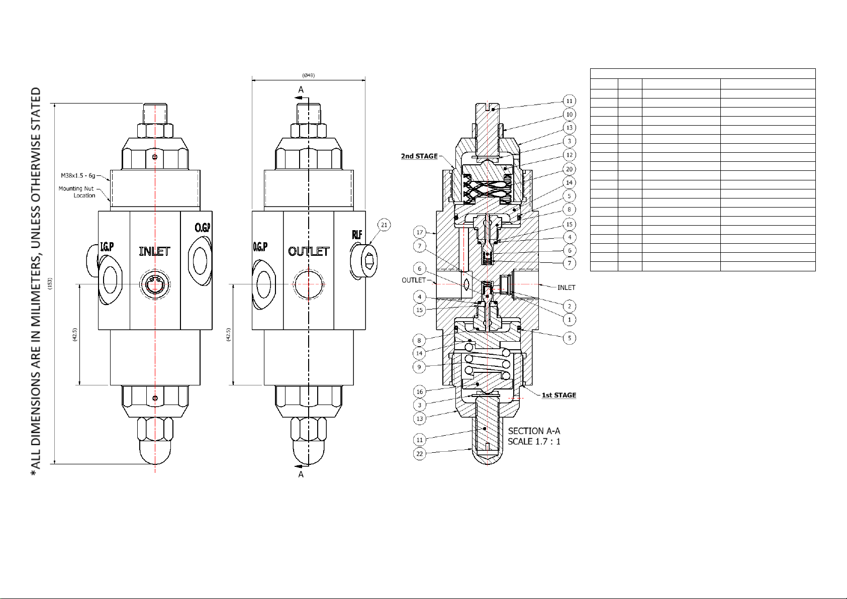
*NOTE: Fig 1 should be used as a reference for the following set of instructions
6.1.1. Accessing the Main Valve Assembly 1st Stage
Please be aware that the first stage let down pressure will require re-setting after service.
To access the Main Valve Assembly (MVA):
i. With the flats of the regulator body (17) secured in a vice*, use a 13mm open
ended spanner to remove the dome nut (22).
*NOTE: Soft vice jaws must be used, when securing the body within the vice
against flats. Due to the position of the flats, it may be necessary to angle the
body in the vice with the 1st stage facing upright for access.
ii. Using a slotted screwdriver, turn the short adjusting screw (11) anti clockwise
until the load from the spring (9) has been released.
iii. Loosen and remove the 1st stage bonnet (13) using a 27mm open ended wrench.
iv. Remove the upper spring rest (16) and load spring (9) from the assembly.
v. Remove the sensor (14) (inclusive of O-ring 5), by using pliers to grip the flats of
the sensor and lift from the assembly.
vi. Remove/replace the O-ring (5) from around the sensor (14), ensuring that
adequate lubrication is used.
vii. The seat retainer (8) can then be removed using a 12mm socket.
viii. Remove the soft seat* (15) and O-ring (4).
*NOTE: inspect the sealing face of the soft seat, for any potential damage and
replace where necessary.
ix. Remove the main valve* (6) and main valve spring (7) from the assembly.
*NOTE: inspect the sealing cone face of the main valve, for any potential damage
and replace where necessary.
Re-assembly
x. Place the main valve spring (7) over the lower stem main valve (6) and place both
parts into the regulator body (17)
xi. Place the O-ring (4) into regulator body (17).
xii. Guide the soft seat* (15) over the upper stem of the main valve (6) and into the
regulator body (17), ensuring that the O-ring (4) is seated into the O-ring groove
of the soft seat (15).
*NOTE: Taking care not to damage its sealing face against the tip of the valve.
xiii. Guide the seat retainer (8), over the upper stem of the main valve (6) and
screw/tighten into the regulator body (17), using a 12mm socket and torque to
17Nm.
xiv. Place the sensor (14) (inclusive of O-ring 5), into the regulator body (17).
xv. Place the load spring (9) onto the sensor (14) and place the upper spring rest (16)
onto the top of the load spring (9).
xvi. Screw the 1st stage bonnet (13) onto the assembly and using a torque wrench
with a 27mm open ended attachment, tighten to 20Nm.