Installation Instructions
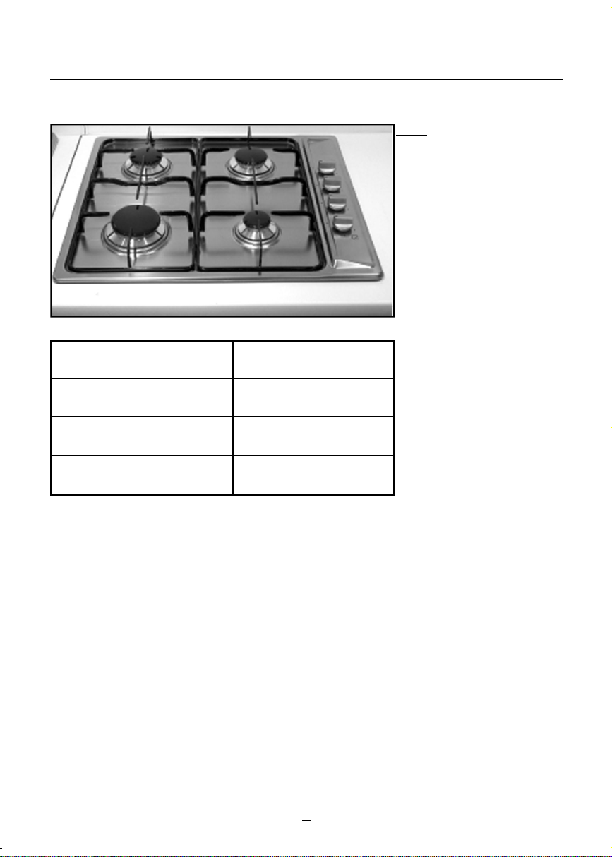
TECHNICAL INFORMATION
lThe installation, the adjustments, conversions and maintenance listed in this
part must only be carried out by qualified persons.
lThe safety and automatic adjustment devices of the appliance may only be
modified by an authorised Belling service agent.
lThe installation of this gas hob must comply with the standards in force.
lThis appliance is not connected to a flue for discharge of the combustion
products; therefore, it must be connected in compliance with the above
mentioned installation rules. Particular attention must be paid to the
instructions given below for ventilation and aeration.
L O C A T I O N
The cooker may be located in a kitchen, kitchen/diner or a bed-
s itting room, but not in a room containing a bath or shower. The
hob must not be installed in a bed-sitting room of less than 20 m3.
LPG models shall not be installed in a room or internal space below
g r ound level, e.g. in a basement.
PROVISION FOR VENTILATION
The room containing the cooker should have an air supply in
a c c o rdance with BS 5440: Part 2.
The room must have an opening window or equivalent; some ro o m s
m ay also re q u i r e a permanent vent. If the room has a vo l u m e
between 5 and 10 m3, it will re q u i r e an air vent of 50 cm2e ffe c t i ve
a rea unless it has a door which opens dire c tly to outside. If the
room has a volume of less than 5 m3, it will re q u i r e an air vent of
100 cm2e f fe c t i ve area (fig. 1). If there are other fuel burning
a p p liances in the same room, BS 5440: Part 2 should be consult e d
to determine air vent re q u i r e m e n t s .
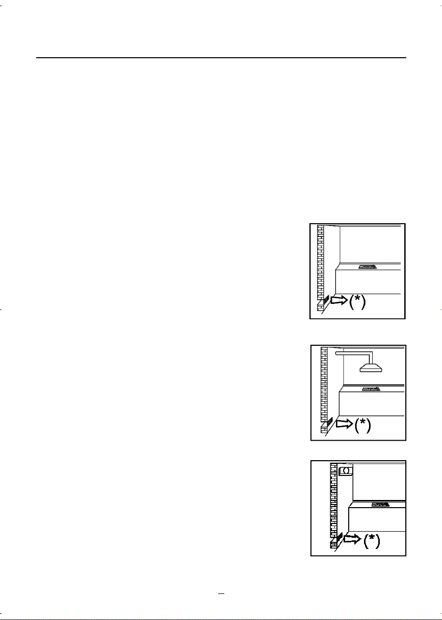
NOTE: the use of a gas cooking appliance re s u l ts in the pro d u c t i o n
of heat and moisture in the room in which it is installed. Alway s
e n s u re that the kitchen is well ve n t i lated; keep natural ve n t il a t i o n
holes open or install a mechanical ve n t i lation device (fig. 2).
In particular, when using the grill or more than one hotplate burner,
open a window if a mechanical ve n t i lation device is not opera t i n g
(fig. 3).
(*) Air inlet - minimum section: 100 cm2
5
FIG. 1
FIG. 2
FIG. 3
Zepa GH60.qxd 19/9/07 8:55 Page 7