Presys TY-2090 User manual

Universal
Smart Transmitter
TY-2090
Technical Manual
R
presys

PRESYS | Instruments TY - 2090
EM0014-01
Table of Contents
Page
1 - Introduction.........................................................................................
1
1.1 - Description..........................................................................................................
1
1.2 - Order Code...........................................................................................................
2
1.3 - Technical Specifications......................................................................................
4
2 - Installation...........................................................................................
6
2.1 - Mechanical Installation.........................................................................................
6
2.2 - Electrical Installation............................................................................................
6
2.3 - Process Input Signal Connection.........................................................................
7
2.3.1 - Thermocouple Connection................................................................................
8
2.3.2 - RTD Connection...............................................................................................
8
2.3.3 - Milliampere Input..............................................................................................
9
2.3.4 - Voltage Source Connection in mV or V ...........................................................
10
2.4 - Output Signal Connection....................................................................................
11
2.5 - Connection Diagram............................................................................................
13
2.6 - Communication....................................................................................................
14
3 - Operation............................................................................................................
14
3.1 - Normal Operation................................................................................................
14
3.2 - Configuration.......................................................................................................
15
4 - Maintenance.......................................................................................................
27
4.1 - Transmitter Hardware..........................................................................................
27
4.2 - Hardware Configuration.......................................................................................
28
4.3 - Optional Module Connection................................................................................
30
4.4 - Calibration...........................................................................................................
33
4.5 - Hardware Maintenance Guidelines......................................................................
38
4.6 - Parts Listing.........................................................................................................
40
4.7 - Recommended Spare Parts Listing......................................................................
43
presys
PRESYS | Instruments TY - 2090
Page 1
1 - Introduction
1.1 - Description
The PRESYS TY-2090 Transmitter is a microprocessor-based instrument which
receives any process variable found in industrial plants as: temperature, pressure, flow,
level, etc. It has non-volatile internal memory (E2PROM) for storing calibration values.
It can communicate with computers through the optional Communication Module
RS-232 or RS-422/485.
The Transmitter is capable of monitoring two
universal standard inputs, accepting direct connection of
thermocouples, RTDs, current (mAdc) and voltage
(mVdc and Vdc). The thermocouple and RTD inputs are
automatically linearized by means of tables stored in the
EPROM memory. A 24 Vdc voltage source, output-
isolated and with short circuit protection, is provided to
power the standard field two-wire transmitters.
The type of input chosen by the user is enabled by
jumpers and by configuration via software. All
configuration data can be protected by a password
system, and are stored in the non-volatile memory in
case of power failure.
The Transmitter has been designed with basis on
modularity concept and accepts up to 4 output cards.
The possible output types are: analog, SPDT relay, solid-
state relay and open collection voltage. Outputs are
electrically isolated from inputs.
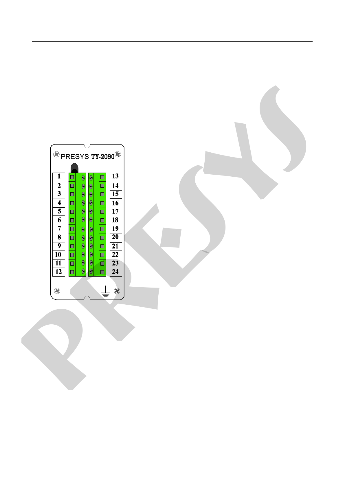
Fig. 1 - Front view of
TY-2090 Transmitter
It allows universal power supply from 90 to 240 Vac.
The instrument is housed in an extruded aluminum case which makes it highly
immune to electrical noise, electromagnetic interference, and resistant to the most severe
conditions of industrial usage.
presys

PRESYS | Instruments TY - 2090
Page 2
1.2 - Order Code
Order Code
TY - 2090 - ___ - ___ - ___ - ___ - ___ - ___ - ___
A B C D E F G
Field A Output 1
0 Not used
1 4 to 20 mA
2 1 to 5 V
3 0 to 10 V
4 SPST Relay
5 Open collector voltage
6 Solid-state relay
Field B Output 2
Same coding as for output 1
Field C Output 3
0 Not used
1 SPDT Relay
2 Open collector voltage
3 Solid-state relay
Field D Output 4
Same coding as for output 3
Field E Power supply
1 90 to 240 Vac
2 24 Vdc
Field F Communication
0 Not used
1 RS 232
2 RS 485
3 RS 422
Field G Case protection degree
0 General usage, sheltered place, mounting on surface
1 General usage, sheltered place, mounting on DIN rail
2 Dust proof
3 Weather proof
Note - Ranges and input types, the use of relays as alarms and alarm points are, among others,
items which the user can program through the MCY-20 Configuration Module (if desired, specify
such information so the whole programming may be previously done by PRESYS).
Note: Any other software or hardware characteristic desired may be available upon request.
presys

PRESYS | Instruments TY - 2090
Page 3
Code Example:
1) TY-2090 - 1 - 0 - 1 - 0 - 1 - 0 - 0
This code defines a TY-2090 Transmitter with channel 1 output of 4-20 mA, which
does not use the channel 2 output, has a SPDT relay for alarming, power supply within the
range of 90-240 Vac, does not use RS communication, to be used in sheltered place with
surface mounting.
1.3 - Technical Specifications
Inputs:
•Two thermocouple configurable inputs (J, K, T, E, R, S, according to ITS-90), RTD
Pt-100 under DIN 43760, 4 to 20 mA, 0 to 5 Vdc, 1 to 5 Vdc, 0 to 10 Vdc. Input
impedance of 250 for mA, 10 Mfor 5 Vdc and 2 Mabove 5 Vdc. Table 1
shows the temperature range limits for thermocouple and RTD, besides the
resolution for linear input sensors.
Input Sensor
Range
Thermocouple
lower limit ºF
upper limit ºF
lower limit ºC
upper limit ºC
Type J
-184.0
1886.0
-120.0
1030.0
Type K
-346
2498
-210
1370
Type T
-418
752
-250
400
Type E
-148.0
1436.0
-100.0
780.0
Type R
-58
3200
-50
1760
Type S
-58
3200
-50
1760
RTD
Pt-100, 2 or 3-
wire
-346.0
1256.0
-210
680.0*
Linear
Range
Resolution
Voltage
0 to 55 mV
3 V
0 to 5 V
250 V
0 to 10 V
500 V
Current
0 to 20 mA
1 V
(*) including wire resistance
Table 1 - Input Sensor Measuring Range
Note: The specifications contained in Table 1 refer to analog/digital conversion and are
accessed by RS232 and RS-422/485 serial communication. For analog output, for
example 4-20 mA, the resolution is 0.075 % of full scale.
presys

PRESYS | Instruments TY - 2090
Page 4
Outputs:
•Analog output of 4-20 mA, 1 to 5 Vdc, 0 to 10 Vdc, use of optional cards with
fitting foreseen for up to two 300 Vac modules galvanically isolated from inputs
and power supply.
•Alarm outputs with SPDT relays with capacity of 3 A 220 Vac, or up to 10 A 220
Vac upon order. In such case, the alarm module is not fitted by means of a
connector, but is welded on the base board. Up to 4 modules can be fitted.
•Logic Level, through open collector, 24 Vdc, 40 mA maximum with isolation.
•Solid-state relay, 2 a 250 Vac with isolation.
Serial Communication:
RS-232 or RS-422/485 with isolation at 50 Vdc, as an optional module with fitting
independent from outputs.
Configuration:
By RS-232 and RS-422/485 serial communication or through the MCY-20
Configuration Module.
Scanning Time:
Standard time of 100 ms.
Accuracy:
0.1 % of full scale for input of TC, RTD, mA, mV, Vdc with acquisition through RS-
232 and RS-422/485 communication.
0.2 % of full scale for analog output and maximum load of 750 .
Linearization:
0.1 ºC for RTD and 0.2 ºC for TC.
Square Root Extraction:
0.5 % of readings for input above 10 % of range.
Cut-off programmable from 0 to 5 %.
Cold Junction Compensation:
2.0 ºC at ambient temperature from 0 to 50 ºC.
Stability at ambient temperature:
0.005 % per ºC of range referred to an ambient temperature of 25 ºC for
acquisition in RS-232 and RS-422/485.
0.015 % per ºC of range referred to an ambient temperature of 25 ºC for analog
output.
Power Supply:
90 to 240 Vac Universal, (10 W nominal); 24 Vdc or other values are optional.
presys

PRESYS | Instruments TY - 2090
Page 5
2 - Wire Transmitter Power Supply:
24 Vdc voltage and 50 mA maximum, isolated from outputs, with short-circuit
protection.
Operating ambient:
0 to 50ºC temperature and 90% maximum relative humidity.
Dimensions:
140mm x 53mm x 156mm (height, width, depth).
Weight:
0.5kg nominal.
Warranty:
One year.
presys

PRESYS | Instruments TY - 2090
Page 6
2 - Installation
2.1 - Mechanical Installation
The TY-2090 Transmitter can be mounted on a surface or on all types of existing
DIN rail, as illustrated in the figure below.
Fig. 2 - Dimensional drawing and detail of the adapter for DIN rail
2.2 - Electrical Installation
The TY-2090 Transmitter can be powered with any voltage between 90 and 240
Vac or Vdc. Note that power is always applied to the internal circuit when the instrument is
connected to the AC supply.
Connections of process input and output signals should only be made with the
power off.
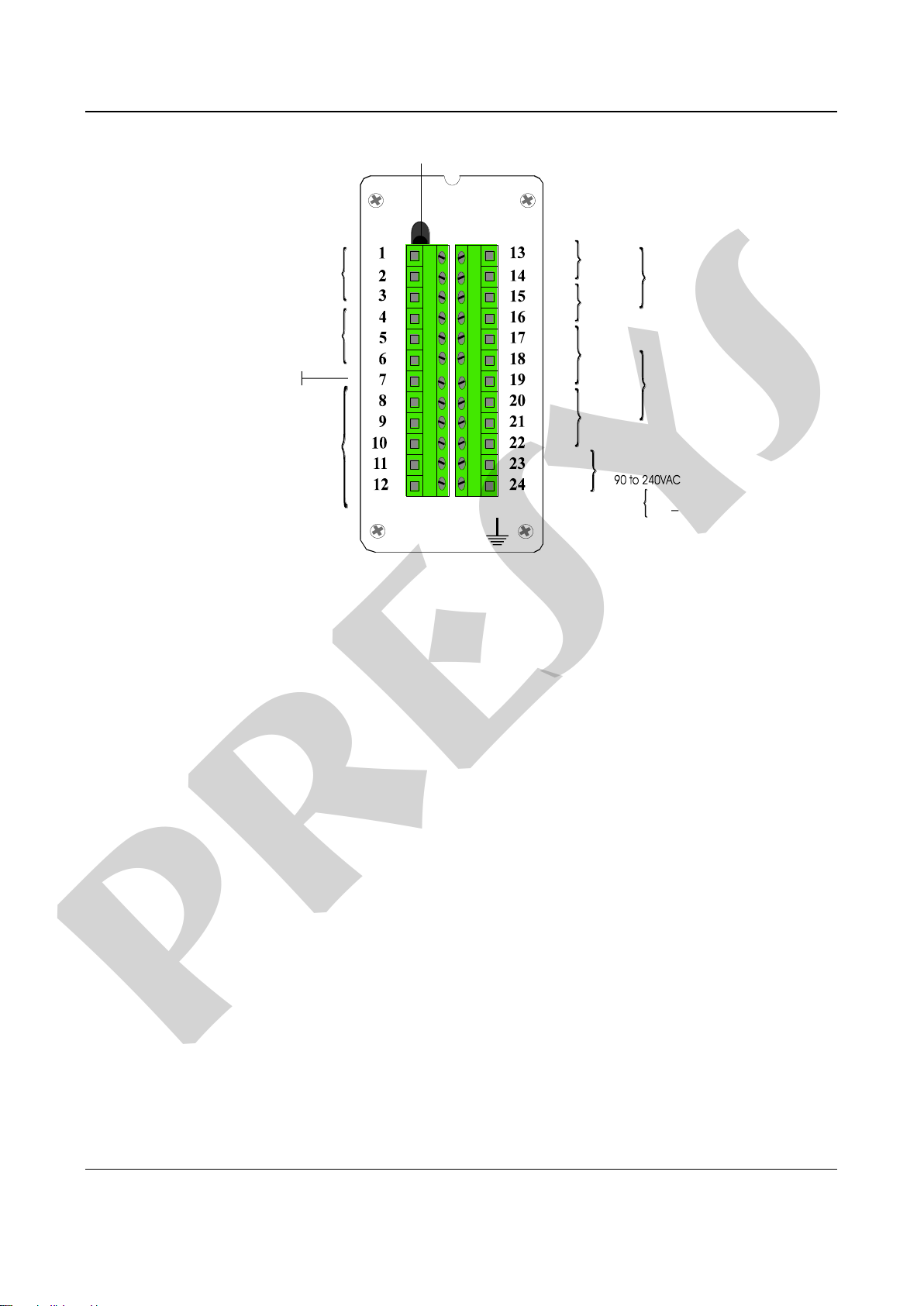
Figure 3 shows the instrument I/O terminal scheme with all designations for power
supply, grounding, communication and process input and output signals.
Signal cables should be kept as far away as possible from power supply cables.
Since the instrument housing is a metallic case, it is necessary to connect the
instrument ground terminal (gnd earth) to the local earth ground; this terminal should never
be connected to the neutral terminal.
presys
PRESYS | Instruments TY - 2090
Page 7
Fig. 3 - Transmitter terminals
2.3 - Process Input Signal Connection
The Transmitter, in its two standard universal inputs, can be connected to
thermocouples, 2 or 3-wire RTDs, mA, mV or V. In order to know the input sensor types
refer to Table 1, section 1.3 on Technical Specifications.
The enabling of a certain type of input sensor is obtained by means of internal
jumpers (refer to section 4.2, Hardware Configuration) and by proper sensor selection in
configuration time (refer to section 3.2, Configuration). Therefore, the connections
explained below, will only become effective if the instrument is correctly configured in
terms of hardware and software.
The wiring of a type of sensor to input 1 does not restrict the simultaneous use of
another sensor, of the same type or different type, for input 2.
In order to prevent noise induction in the wire connecting the sensor to the I/O terminal,
use twisted pair cable and run the sensor connection wires through a metallic conduit or
use a shielded cable. Be sure to connect only one shielded wire end to the negative I/O
terminal or to the sensor ground, as outlined in the following items.
WARNING: THE GROUNDING OF THE TWO SHIELDED WIRE ENDS MAY CAUSE
DISTURBANCE TO THE TRANSMITTER.
COMMUNICATION
INPUT 2
INPUT 1
COLD JUNCTION SENSOR
+24V - TPS
POWER SUPPLY
OUTPUT 2
OUTPUT 1
NEUTRAL
PHASE
ANALOG OUTPUT
OR
ALARMS
OUTPUT 4
OUTPUT 3
ALARMS
TY-2090
GND
EARTH
+
+
_
_
24Vdc 23 (+)
24 ( )
presys

PRESYS | Instruments TY - 2090
Page 8
2.3.1 - Thermocouple Connection
Whenever using just one thermocouple, the user should preferably connect it to
input 1 of the Transmitter, in order to obtain greater accuracy, since the cold junction
sensor is solidly attached to the I/O terminal and closer to input 1.
In order to reduce cold junction compensation error, apply thermal paste from the
I/O terminal to the cold junction sensor.
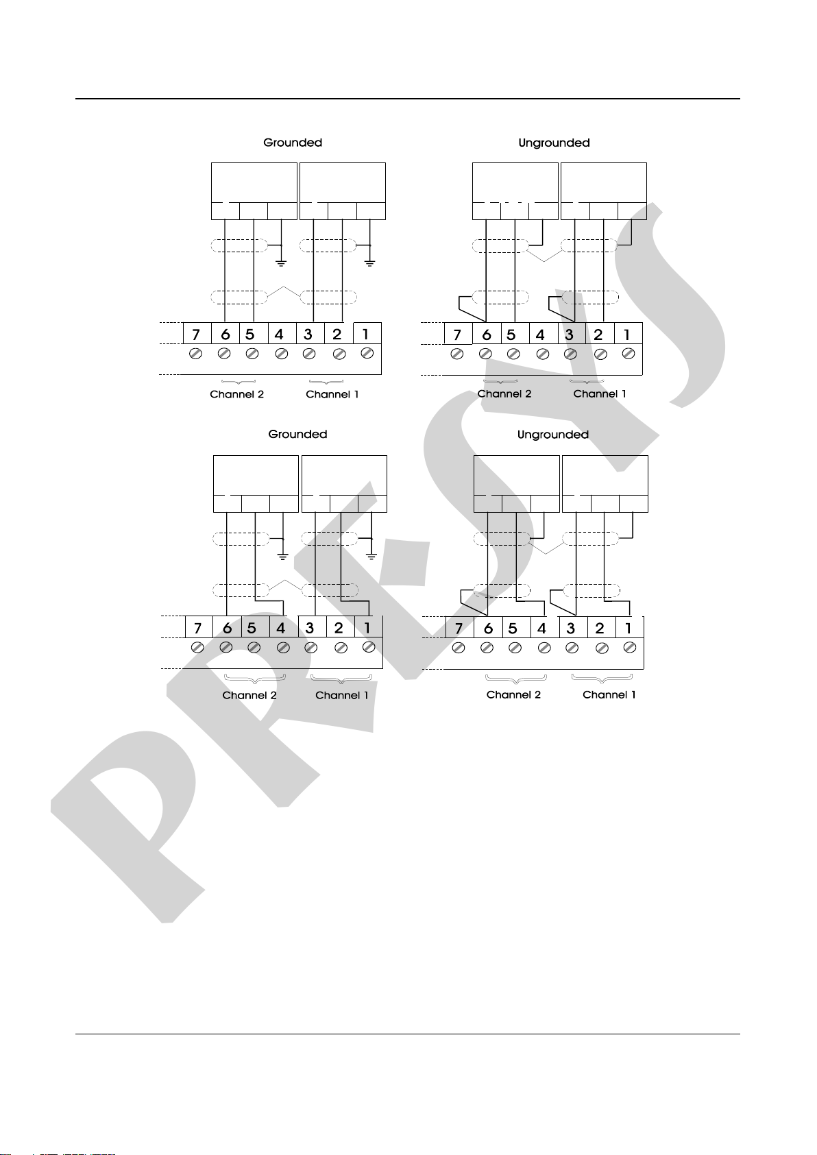
Connect the thermocouple to terminals 2 (+) and 3 (-) in order to use the input 1, or
connect to terminals 5 (+) and 6 (-) to use the input 2, as shown in figure 4.
Use compensation cables of the same construction material as the thermocouple to
connect the thermocouple to the Transmitter I/O terminals. Check that the thermocouple
polarity is the same as that of the I/O terminals.
Fig. 4 - Thermocouple Connection
2.3.2 - RTD Connection
The RTD can be connected to 2, 3 or 4 wires. All connection types are shown in
figure 5.
For 2-wire RTD, connect the RTD between I/O terminals 1 and 3 to use input 1, or
to terminals 4 and 6 to use input 2, as illustrated in figure 5.
For 3-wire RTD, connect the RTD in the same way as described for a 2-wire
connection, and connect the third wire for RTD compensation to terminal 2 in case of input
1, and to terminal 5 in case of input 2, see figure 5.
6 5 4 3 2 1
6 5 4 3 2 1
- + - +
- + - +
Grounded Ungrounded
Thermocouple
Note 1
Note 1
Twisted pair or
shielded wire
Channel 2 Channel 1 Channel 2 Channel 1
Note1: Keep shielded wire disconnected at this end.
presys

PRESYS | Instruments TY - 2090
Page 9
A 4-wire RTD is connected to the Transmitter in the same way as a 3-wire RTD,
except that the fourth wire is disregarded and left disconnected, see figure 5.
A 3-wire RTD provides greater accuracy than a 2-wire RTD.
The RTD wiring should be of the same material, length and gauge to ensure proper
resistance compensation of connecting wires. The maximum resistance of connecting
wires is 10 per wire. The minimum gauge should be 18 AWG for distances up to 50
meters and 16 AWG for distances superior to 50 meters.
Fig. 5 - RTD Connection
2.3.3 - Milliampere Input
A standard current source of 4 to 20 mA can be applied between terminals 1 (+)
and 3 (-) in case of input 1, and between terminals 4 (+) and 6 (-) in case of input 2. Such
current can be originated from a transmitter with external power supply.
6 5 4 3 2 1
6 5 4 3 2 1
6 5 4 3 2 1
6 5 4 3 2 1
6 5 4 3 2 1
6 5 4 3 2 1
GROUNDED
UNGROUNDED
2-WIRE 3-WIRE 4-WIRE
2-WIRE 3-WIRE 4-WIRE
Channel 2 Channel 1 Channel 2 Channel 1 Channel 2 Channel 1
Channel 2 Channel 1
Channel 2 Channel 1 Channel 2 Channel 1
Note 1: Let the shield wire disconnected at this end.
Note 1 Note 1 Note 1 Note 1
Note 1
Note 1
Note 1
Note 1
RTD
RTD RTD RTD
RTD RTD
NC NC
NC NC
presys

PRESYS | Instruments TY - 2090
Page 10
If the Transmitter internal voltage source of 24 Vdc is used to power a 2-wire
transmitter, the current is received only by terminal 1 (+) in case of input 1, and it is
received only by terminal 4 (+) in case of input 2. Figure 6 illustrates both possibilities of
connection.
Fig. 6 - Current Source Connection
2.3.4 - Voltage Source Connection in mV or V
Voltages from 0 to 55 mVdc or from 0 to 5 Vdc should be applied between terminals
2 (+) and 3 (-) in case of input 1, and between terminals 5 (+) and 6 (-) in case of input 2.
Voltages from 0 to 10 Vdc should be applied between terminals 1 (+) and 3 (-) in case of
input 1, and between terminals 4 (+) and 6 (-) in case of input 2. These connections are
illustrated in figure 7.
Two-wire Transmitter
Note 1: Keep shielded wire disconnected at this end.
Note 2: Connect shielded wire to transmitter ground terminal. If ground terminal non-existent keep shielded wire disconnected at this end.
(Transmitter should not
be grounded)
4-wire Transmitter
Ungrounded Transmitter
presys
PRESYS | Instruments TY - 2090
Page 11
Fig. 7 - Voltage Source Connection
2.4 - Output Signal Connection
The Transmitter, in its most complete version, can be provided with up to four
output signals: output 1, output 2, output 3 and output 4. Outputs 1 and 2 are used as
retransmission outputs or alarm outputs. Outputs 3 and 4 are used only as alarm outputs.
In case of outputs 1 and 2, there are six different output types, which can be obtained
between I/O terminals: retransmission output (4 to 20 mA, 0 to 5 Vdc or to 10 Vdc), SPST
relay, open collector voltage and solid-state relay.
Note 1: Keep shielded wire disconnected at this end.
Note 2: Connect shielded wire to power supply ground terminal. If ground terminal non-existent keep shielded wire disconnected at this end.
_
_
_
_
_
_
_
_
+ G
+ G
+ G
+ G
+ G
+ G
+ G
+ G
0 to 55mV 0 a 55mV
0 to 55mV 0 to 55mV
0 to 5V
0 to 10V 0 to 10V 0 to 10V0 to 10V
0 to 5V
0 to 5V 0 to 5V
or or
or or
_
_
_
_
+
+
+
+
_
_
_
_
+
+
+
+
Note 1
Note 1
Note 2
Note 2
Power supply should
not to be grounded
Power supply should
not to be grounded
presys

PRESYS | Instruments TY - 2090
Page 12
For outputs 3 and 4 there are three different output types: SPDT relay, open
collector voltage and solid-state relay. Figure 8 shows the Transmitter outputs.
Notice that the I/O terminals will only show output signals if the corresponding
optional module is installed and the output is correctly configured. In case of analog
outputs, refer to sections 3.2, Configuration, and 4.3, Optional Module Connection, for
details on installation and configuration of optional modules.
(*) Relay contacts assume that SAFE condition (see section 3.2 on Configuration) was selected for relays
and that the Transmitter is powered and is under non-alarm condition. With no power supply or under alarm
condition, contact states change.
Fig. 8 - Output Connections
13
14
15
16
OUTPUT 1
OUTPUT 1
OUTPUT 3
OUTPUT 2
OUTPUT 2
OUTPUT 4
13
14
15
16
17
18
19
20
21
22
FUNCTION INTERNAL DEVICE TERMINALS
ANALOG OUTPUT
ALARM
4 to 20mA 0 to 5V 0 to 10V
4 to 20mA 0 to 5V 0 to 10V
SCR
SCR
SPST
SPST NC
C
C
SCR
SCR
SPDT
SPDT
NC
NC
C
C
NO
NO*
+24V
+24V
+24V
+24V
Logic
Logic
Logic
Logic
+
-
+
-
NC
*
*
*
*
*
presys

PRESYS | Instruments TY - 2090
Page 13
2.5 - Connection Diagram
12
3
4
5
678
910
1112
13
14
1516
17
18
1920
21
22
23
24
GND
EARTH
COMMOM Tx- Tx+ Rx- Rx+
COMMUNICATION
INPUT 2 INPUT 1
POWER SUPPLY
OUTPUT 4 OUTPUT 3 OUTPUT 2 OUTPUT 1
NEUTRAl LINE
SCR SCR SCRSCR
+24V +24V +24V +24V
Logic Logic Logic Logic
+
+
+
+
C
NC
(1)
C
NC
(1)
NC
C
NO
(1)
(1)
NC
C
NO
(1)
(1)
+
+
RTD
Current 4 to 20mA
Voltage 0 to 10V
COMMOM Tx Rx
GND
RS-232
Relay 1Relay 3Relay 4 Relay 2
Transmitter Power Supply +24V
RS-422/485
Alarms
+
+
+
+
Retransmittion
4 to 20 mA
0 to 5 V
0 a 10 V
Notes:
(1) Relay contacts (NC and NO) suppose that the transmitter
is powered and under non-alarm condition.
(2) Optional modules.
(2)
(2)
(2)
24Vdc 23 (+)
24 ( )
presys

PRESYS | Instruments TY - 2090
Page 14
2.6 Communication
The TY-2090 Transmitter can communicate with computers via RS-232 or RS-
422/485 provided the optional communication module is installed and the proper
communication parameters are configured via software.
Specific information about communication and signal connection can be found in
the Communication Manual.
3 - Operation
3.1 - Normal Operation
The TY-2090 Transmitter has two operation modes: normal operation and operation
in configuration time.
In normal operation the Transmitter retransmits the process variable to a remote
point either through its two analog outputs 1 and 2, or via RS-232 or RS-422/485
communication. The analog outputs 1 and 2 can retransmit input 1 as well as input 2. The
two analog outputs can even retransmit the same input. Moreover, the Transmitter checks
the alarm conditions and activates the alarm outputs 3 and 4 if it is the case.
The Transmitter has a portable configuration unit, MCY-20, which is connected to it
by means of a DB-25 connector, as illustrated in figure 9 below.
PRESYS MCY - 20
Fig. 9 - MCY-20 Portable Configuration Module
presys

PRESYS | Instruments TY - 2090
Operation
Page 15
When the MCY-20 Configuration Module is connected to the Transmitter under
normal operation, the instrument begins to function as a transmitter and as a process
monitor as well, through the Module display.
Under configuration time operation mode the user, through the MCY-20
Configuration Module, selects and assigns values to the parameters which regulate the
Transmitter functioning, when in normal operation. Such parameters are, among others,
alarm set-point values, retransmission output range, etc.
The normal operation mode, in which the Transmitter operates most of the time, will
be named level zero. At this level, the keys on the MCY-20 Configuration Module front
panel have the following functions:
ENTER
Key
Switches from level zero to level 1 or asks for the
password, depending on the configuration.
DOWN
Key
Changes the channel shown on display. If the display was
showing channel 1 (2), after pressing the DOWN key, the
display changes for the measured variable of channel 2
(1).
3.2 - Configuration
To gain access to the configuration mode, one should match the password
established with the purpose of preventing unauthorized people from altering the critical
parameters of the process.
Therefore, whenever the ENTER key is pressed under normal operation mode, one
of the following cases might occur:
i) Enter directly into level 1 (GENERAL) of configuration mode, indicating that the
instrument was not configured with the password system.
ii) The Module display shows the PASSWORD warning, indicating that the instrument has
a password system by key or by value, as illustrated in figure 10.
presys

PRESYS | Instruments TY - 2090
Page 16
Fig. 10 - Password system by key and by value
In case of password by key, the user should press the UP, DOWN and ENTER keys
in sequence to enter the configuration levels.
In case of password by value, the user should press the ENTER key a second time
to obtain the number 00000, with the last digit blinking on the right. The blinking digit
indicates the position where the digit of a 4-digit number will be entered by the user. In
order to move to the next digits on the left, the user should press the ENTER key. After
entering all digits, the user can press the ENTER key once more to switch to level 1 in
case the password is correct, otherwise the system reverts to normal operation ( see
figure 10).
The user can even select both password systems, by key and by value. In such
case, if upon receiving a request for a password the user enters a wrong key sequence, he
will be immediately reverted to password by value.
The password can be a number chosen by the user (customized) or the number
2090. Notice that in case of password by value the number 2090 is always enabled,
serving as a help to the user in case he forgets his password. In order to enter a password
number or any other parameter value, the user can use the front Module keys, which have
the following functions:
UP
Key
Increases the digit
DOWN
Key
Decreases the digit
ENTER
Key
Moves to digit on the left
All configuration parameters are stored in the non-volatile memory and determine
the instrument normal operation. Through such parameters the user can adapt the
instrument according to his requirements, if he desires to change the factory configuration.
PASS
PASS 0000
GENERAL
GENERAL
RIGHT
RIGHT
WRONG
WRONG
OPERATION
OPERATION
presys

PRESYS | Instruments TY - 2090
Operation
Page 17
The configuration parameters are distributed over six increasing hierarchical levels,
as shown in figure 11.
In order to go through those levels and access the corresponding parameters the
user may use the Module front keys with the following functions:
ENTER
Key
Switches into each level
UP
Key
Switches to higher level
DOWN
Key
Switches to a lower level
Note: in the following diagrams, the Module display is represented by rectangles in response to the selection of ENTER,
UP and DOWN keys.
Fig. 11 - Diagram of parameter levels
The hierarchical levels are presented in sequence. The options of each level with all
corresponding parameters are explained step by step.
Within each level, the front panel keys of the MCY-20 Configuration Module have
the following functions:
UP
Key
Scrolls the options in ascending order
DOWN
Key
Scrolls the options in descending order
ENTER
Key
Confirms or advances the options within
the level whenever the display does not
show ESC. When the display shows
ESC, one goes back one or more
positions.
RS
LEVEL 6
LEVEL 5
LEVEL 4
LEVEL 3
LEVEL 1
LEVEL 0
LEVEL 2
OUTPUT
INPUTS
CALIB
ALAR
GENERAL
GENERAL
PASS
OPERATION
presys

PRESYS | Instruments TY - 2090
Page 18
Level 1 - General
In level 1 we have the options: TAG, SOFT, PASSWORD and INDIC (see figure
12).
TAG - Enables an alphanumeric identification for the instrument. The procedure
used to enter a TAG or any other parameter is the same as for the previously described
password (see the functions of ENTER, UP and DOWN keys under password by value).
SOFT - Shows the software version number.
PASSWORD - Allows whether to define or not a password system to access the
configuration mode. The password system can be defined by key, by value (number
chosen by the user and the number 2090) or both. The key sequence for defining a
password by key is, as explained above, to press the UP, DOWN and ENTER keys in that
order.
INDIC - Within the option for the indication of the variable measured on display of
MCY-20 Module, it is possible to view the values related to channel 1 and channel 2 by
pressing the DOWN key or allowing the instrument to toggle between the measured
variable values of each channel. In the first instance, NO is selected for option TWO, and
in second instance, YES (automatic scanning mode) is selected for option TWO, together
with the display time, in seconds, assigned to each channel.
Fig. 12 - GENERAL Level Options
presys
Other manuals for TY-2090
1
Table of contents
Other Presys Transmitter manuals

Popular Transmitter manuals by other brands


Aras
Aras CTINT1000 user manual

Mutec
Mutec MTP200ib-E manual

Transmitter Solutions
Transmitter Solutions Firelly 3 SU7L318ALD21K3 manual

MTS Systems
MTS Systems Level Plus LP Series Safety manual

Phonak
Phonak roger Quick setup guide

Critical Environment Technologies
Critical Environment Technologies LPT Operation manual