Part 2 Installation
2.3 Gas Connections
e EMD-570 with its standard ow through housing is designed for positive pressure samples and requires
incoming sample lines. e user is responsible for added sample system components as well as sourcing a
calibration gas (although you may use ambient air as your calibration gas).
It is recommended to use Stainless Steel Tubing or a low permeable plastic tubing.
• Flow rate should be between 0.5 - 3 SCFH
• Inlet pressure should be between 5 - 60 PSIG
• Analyzer should be vented to atmosphere, take precau-
tion to make sure vent does not get blocked
1
2
3
4
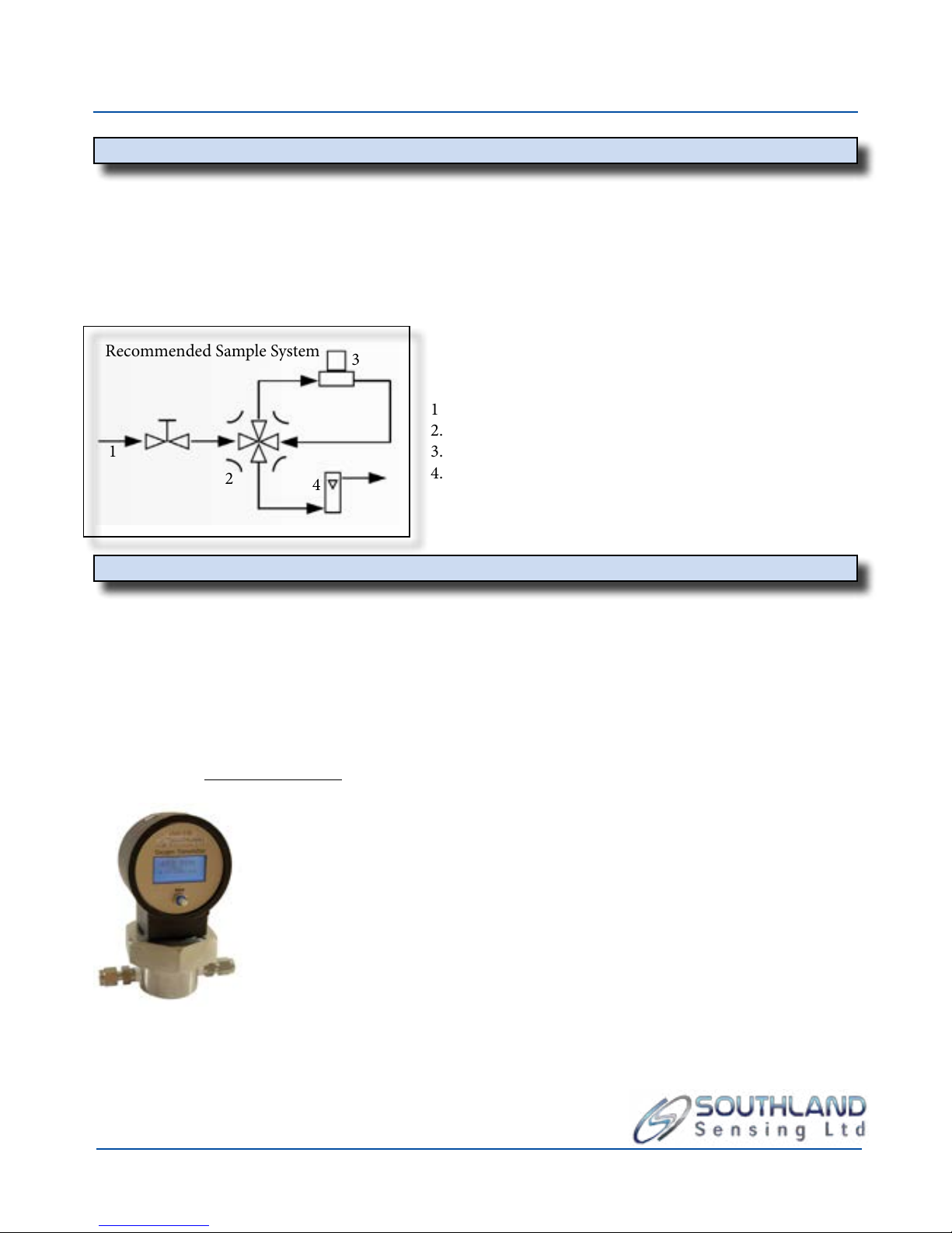
1 Sample Gas Inlet, goes into Flow Valve
2. Bypass valve, allows user to isolate sensor during shutdown
3. EMD-570 Transmitter with Flow rough Housing
4. Flow Meter, Vent to Atmosphere
Recommended Sample System
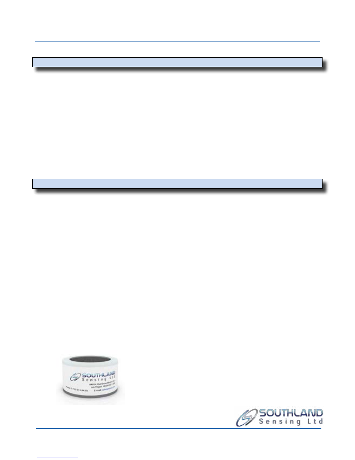
2.4 Installing the Oxygen Sensor
CAUTION: Prior to installing the oxygen sensor. Read section 4.1 or 4.2 on performing a span calibration.
e EMD-570 can accept either a TO2-1x or TO2-2x (CO2 Applications) trace oxygen sensor. For proper selection
with your application, please view our online application guide or contact your local sales rep.
Prior to installing the sensor, it is important to make sure that the analyzer gas lines are hooked up and the unit is
ready to purge with a zero gas. Connect the zero gas line and set your ow between 0.5 - 3.0 SCFH.
To Install the Sensor:
- Remove the upper electronics housing by unscrewing the stainless steel collar.
- Inspect O’ring for cracking, replace if necessary. Always lube your Orings!
- Remove the sensor from its box. With scissors, open nitrogen purged packaging
and remove the sensor.
- Visually inspect sensor for damage, if damaged notify the factory immediately.
- Remove the shorting pins across the back of the sensor board contacts.
- Place the sensor inside the upper housing with the metal screen mesh facing down
and the circuit board contacts facing up.
- Return upper portion of the device to the stainless steel bottom. Tighten
collar. Hand tight is acceptable to create an airtight seal.
- Immediately start purge of zero gas.
- If the analyzer has not been calibrated, refer to section 4.1 or 4.2 for more information.
** Sensor should be exposed to ambient air for no more than 2 minutes. Extended periods of exposure can damage the low
end sensitivity and response time.