Presys TY-2090 User manual

Universal
Smart Transmitter
TY-2090
EM0319-00
TECHNICAL MANUAL
R
Energy
presys
presys
presys
Universal
presys
Universal
Smart Transmitter
presys
Smart Transmitter
presys

CAUTION!
In case of failure, the instrument can provide AC voltage levels in its metal box,
which for safety reasons must always be connected to an effective ground point. To
this end a suitable terminal is provided on the back of the box identified as GND. Never
connect this terminal to the neutral terminal of power supply.
It is recommended the use of an external fuse (2 A) on the power input of the
instrument. There is an internal fuse.
Operation of relays - Important Note!
When the instrument has relay module for alarm or control, you must follow the
instructions in this manual in the maintenance section on the snubber use.
The snubber is a protection against noise coming from the opening / closing of
the relay contacts, but depending on the application may be necessary to remove this
snubber!
CAUTION!
The instrument described in this manual is a device for use in specialized
technical area. The user is responsible for configuration and selection of values of the
instrument parameters. The manufacturer warns of the risks of occurrences with
damage to both the person and the property resulting from the incorrect use of the
instrument. The information and specifications in this manual are subject to change
without previous notice.
presys
In case of failure, the instrument can provide AC voltage levels in its metal box,
presys
In case of failure, the instrument can provide AC voltage levels in its metal box,
which for safety reasons must always be connected to an effective ground point. To
presys
which for safety reasons must always be connected to an effective ground point. To
this end a suitable terminal is provided on the back of the box identified as GND. Never
presys
this end a suitable terminal is provided on the back of the box identified as GND. Never
It is recommended the use of an external fuse (2 A) on the power input of the
presys
It is recommended the use of an external fuse (2 A) on the power input of the
Operation of relays - Important Note!
presys
Operation of relays - Important Note!
When the instrument has relay module for alarm or control, you must follow the
presys
When the instrument has relay module for alarm or control, you must follow the
instructions in this manual in the maintenance section on the snubber use.
presys
instructions in this manual in the maintenance section on the snubber use.
The snubber is a protection against noise coming from the opening / closing of
presys
The snubber is a protection against noise coming from the opening / closing of
the relay contacts, but depending on the application may be necessary to remove this
presys
the relay contacts, but depending on the application may be necessary to remove this
CAUTION!
presys
CAUTION!
The instrument described in this manual is a device for use in specialized
presys
The instrument described in this manual is a device for use in specialized
technical area. The user is responsible for configuration and selection of values of the
presys
technical area. The user is responsible for configuration and selection of values of the
instrument parameters. The manufacturer warns of the risks of occurrences with
presys
instrument parameters. The manufacturer warns of the risks of occurrences with
damage to both the person and the property resulting from the incorrect use of the
presys
damage to both the person and the property resulting from the incorrect use of the
instrument. The information and specifications in this manual are subject to change
presys
instrument. The information and specifications in this manual are subject to change
without previous notice.
presys
without previous notice.

PRESYS Instruments TY-2090-Energy
EM0319-00
Table of Contents
1.0 - Introduction ............................................................................................................1
1.1 - Description............................................................................................................1
1.2 - Order Code...........................................................................................................2
1.3 - Technical Specifications........................................................................................3
2.0 - Installation ..............................................................................................................5
2.1 - Mechanical Installation..........................................................................................5
2.2 - Electrical Installation .............................................................................................5
2.3 - Process Input Signal Connections ........................................................................6
2.3.1 - RTD Connections...........................................................................................7
2.3.2 - Current Input ..................................................................................................8
2.3.3 - Voltage Inputs ................................................................................................9
2.4 - Output Connections ............................................................................................10
2.5 - Connection Diagram ...........................................................................................12
2.6 - Communication...................................................................................................13
2.7 - Engineering Units................................................................................................13
3.0 - Operation ..............................................................................................................14
3.1 - Normal Operation................................................................................................14
3.2 - Configuration.......................................................................................................17
4.0 - Maintenance..........................................................................................................30
4.1 - Hardware ............................................................................................................30
4.2 - Hardware Configuration ......................................................................................32
4.3 - Using Snubber with relays...................................................................................33
4.4 - Optional Modules Installation..............................................................................34
4.5 - Calibration...........................................................................................................37
4.6 - Hardware Maintenance Instructions....................................................................42
4.7 - List of Components.............................................................................................44
4.8 - List of Recommended Spare Components .........................................................47
5.0 - MODBUS Communication....................................................................................48
5.1 - List of MODBUS Communication Registers........................................................48
5.2 - List of Communication Coils ...............................................................................52
presys
................................
presys
................................
............
presys
............
................................
presys
................................
............
presys
............
1
presys
1
................................
presys
................................
................................
presys
................................
...........
presys
...........
2
presys
2
................................
presys
................................
........................
presys
........................
3
presys
3
................................
presys
................................
................................
presys
................................
..............
presys
..............
5
presys
5
................................
presys
................................
..........................
presys
..........................
5
presys
5
................................
presys
................................
.............................
presys
.............................
................................
presys
................................
................................
presys
................................
........
presys
........
................................
presys
................................
................................
presys
................................
...........................
presys
...........................
................................
presys
................................
................................
presys
................................
................................
presys
................................
................................
presys
................................
................................
presys
................................
................................
presys
................................
................................
presys
................................
................................
presys
................................
............................
presys
............................
................................
presys
................................
................................
presys
................................
...........................
presys
...........................
................................
presys
................................
................................
presys
................................
................................
presys
................................
................................
presys
................................
................................
presys
................................
................................
presys
................................
................................
presys
................................
................................
presys
................................
................................
presys
................................
3.1 - Normal Operation
presys
3.1 - Normal Operation
................................
presys
................................
................................
presys
................................
................................
presys
................................
................................
presys
................................
4.0 - Maintenance
presys
4.0 - Maintenance
................................
presys
................................
................................
presys
................................
4.1 - Hardware
presys
4.1 - Hardware
................................
presys
................................
................................
presys
................................
4.2 - Hardware Configuration
presys
4.2 - Hardware Configuration
................................
presys
................................
4.3 - Using Snubber with relays
presys
4.3 - Using Snubber with relays
................................
presys
................................
4.4 - Optional Modules Installation
presys
4.4 - Optional Modules Installation
................................
presys
................................
4.5 - Calibration
presys
4.5 - Calibration
................................
presys
................................
................................
presys
................................
4.6 - Hardware Maintenance I
presys
4.6 - Hardware Maintenance I
nstructions
presys
nstructions
4.7 -
presys
4.7 -
List of Components
presys
List of Components
................................
presys
................................
4.8 -
presys
4.8 -
List of Recommended Spare Components
presys
List of Recommended Spare Components
5.0 - MODBUS Communication
presys
5.0 - MODBUS Communication
................................
presys
................................
5.1 - List of MODBUS Communication Registers
presys
5.1 - List of MODBUS Communication Registers
5.2 - List of Communication Coils
presys
5.2 - List of Communication Coils

PRESYS Instruments TY-2090-Energy
Introduction
Page 1
1.0 - Introduction
1.1 - Description
The TY-2090-Energy transmitter is ideal for security applications in turbines,
hydroelectric plants and thermoelectric generators. It is a microprocessor-based
instrument which receives any process variable found in industrial plants such as:
temperature, pressure, flow, level etc. Ithas a non-volatile internal memory (E2PROM)
for storing calibration values.
It can communicate with acomputer through an optional RS-232 or RS-422/485
Communication Module. The Transmitter is capable of monitoring two
universal standard inputs, accepting direct connection
of thermocouples, RTDs, current (mAdc) and voltage
(mVdc, Vdc). The RTD inputs are automatically
linearized by means of tables stored in the EPROM. A
24 Vdc power supply,isolated from the output and
with short circuit protection, is provided to power up
standard field two-wire instruments.
The type of input selected by the user is
enabled by jumpers and by configuration via software.
All configuration data can be protected by a password
system and are stored in the non-volatile memory in
case of power failure.
Designed within the concept of modularity, the
transmitter accepts up to 4 output cards. The possible
output types are analog, SPDT relay, SPST relay,
solid-state relay and open collection voltage.
In case of input sensor breaking, the trip alarms
are not triggered (configurable for 4-20 mA and RTD
inputs) and the analog outputs assume preconfigured
safety values. The alarm outputs can be
independently configured to work in latch mode,
demanding the acknowledgement by the operator
through the MCY-20 configurator keys or via
communication in order to be disabled after the
return of the process variable to the normal
condition. The outputs are electrically isolated from
the inputs. In addition to the high and low alarms, the
transmitter can be set for failure alarms (watchdog) triggered by the detectionof broken
sensors connected to the current or RTD inputs.
It allows the use of a universal power supply from 75 to 264 Vac 50/60Hz or 100
to 360 Vdc (any polarity).
The instrument has an extruded aluminum case which makes it highly immune to
electrical noise, electromagnetic interference and resistant to the most severe conditions
of industrial usage.
Fig. 1 -Front view of the
TY-2090-Energy Transmitter
presys
-Energy transmitter is ideal for security applications in turbines,
presys
-Energy transmitter is ideal for security applications in turbines,
is a microprocessor-based
presys
is a microprocessor-based
instrument which receives any process variable found in industrial plants such as:
presys
instrument which receives any process variable found in industrial plants such as:
-volatile internal memory (E2PROM)
presys
-volatile internal memory (E2PROM)
an
presys
an
optional
presys
optional
RS
presys
RS
-232 or RS-422/485
presys
-232 or RS-422/485
The Transmitter is capable of monitoring two
presys
The Transmitter is capable of monitoring two
universal standard inputs, accepting direct connection
presys
universal standard inputs, accepting direct connection
of thermocouples, RTDs, current (mAdc) and voltage
presys
of thermocouples, RTDs, current (mAdc) and voltage
(mVdc, Vdc). The RTD inputs are automatically
presys
(mVdc, Vdc). The RTD inputs are automatically
rized by means of tables stored in the EPROM. A
presys
rized by means of tables stored in the EPROM. A
Vdc power supply
presys
Vdc power supply
,
presys
,
isolated from the output and
presys
isolated from the output and
with short circuit protection, is provided to power
presys
with short circuit protection, is provided to power
standard field two-wire instruments.
presys
standard field two-wire instruments.
The type of input selected by the user is
presys
The type of input selected by the user is
enabled
presys
enabled
by jumpers and by configuration via software.
presys
by jumpers and by configuration via software.
All configuration data can be protected by a password
presys
All configuration data can be protected by a password
system and are stored in the non-volatile memory in
presys
system and are stored in the non-volatile memory in
case of power failure.
presys
case of power failure.
Designed with
presys
Designed with
in
presys
in
the concept of modularity, t
presys
the concept of modularity, t
transmitter accepts up to 4 output cards. The poss
presys
transmitter accepts up to 4 output cards. The poss
output types are analog, SPDT relay, SPST relay,
presys
output types are analog, SPDT relay, SPST relay,
solid-state relay and open collection voltage.
presys
solid-state relay and open collection voltage.
In case of input sensor break
presys
In case of input sensor break
are not triggered (configurable for 4-
presys
are not triggered (configurable for 4-
inputs) and the analog outputs assume preconfigured
presys
inputs) and the analog outputs assume preconfigured
s
presys
s
afety values. The alarm outputs can be
presys
afety values. The alarm outputs can be
independently
presys
independently
demanding the acknowledgement by the operator
presys
demanding the acknowledgement by the operator
through the MCY-
presys
through the MCY-
communication in order to be disabled after the
presys
communication in order to be disabled after the
transmitter can
presys
transmitter can
be
presys
be
set for failure alarms (watchdog) triggered by the detectio
presys
set for failure alarms (watchdog) triggered by the detectio
sensors connected to the current or RTD
presys
sensors connected to the current or RTD
It allows the use of a universal power supply from
presys
It allows the use of a universal power supply from
to
presys
to
360 Vdc (any polarity
presys
360 Vdc (any polarity
The instrument
presys
The instrument
electrical noise, electromagnetic interference and resistant to the most severe conditions
presys
electrical noise, electromagnetic interference and resistant to the most severe conditions
of industrial usage.
presys
of industrial usage.
presys
Fig
presys
Fig
. 1
presys
. 1
-
presys
-
Front view of
presys
Front view of
the
presys
the
TY
presys
TY
-
presys
-
2090
presys
2090
-
presys
-
Energy
presys
Energy
Transmitter
presys
Transmitter

PRESYS Instruments TY-2090-Energy
Introduction
Page 2
1.2 - Order Code
TY -2090
-
A
-
B
-
C
-
D
-
E
-
F
-
G
-
E
H
Field A Output 1 (Retransmission or Alarm)
0
None
1
4to 20 mAdc
2
1to 5 Vdc
3
0 to 10 Vdc
4
SPST Relay
5
Open Collector Voltage
6
Solid State Relay
Field B
Output 2 (Retransmission or Alarm)
Same code as Output 1
Field C
Output 3 (Alarm ortrip)
0
None
1
SPDT Relay
2
Open Collector Voltage
3
Solid State Relay
Field D Output 4 (Alarm ortrip)
Same code as Output 3
Field E
Power Supply
1
75 to 264 Vac 50/60Hz or100 to 360 Vdc (any polarity)
2
24 Vac or 24 Vdc (
10 %)
3
12 Vdc (
10 %)
4
Other, upon request
Field F
Communication
0
None
1
RS-232
2
RS-485
3
RS-422
Field G
Case Protection Grade
0
General usage, sheltered place, surface mounting
1
General usage, sheltered place, DIN rail mounting
2
Weather-proof
3
Explosion-proof (BR-Ex d IIB T6 IP 65), without display (*)
4
Dust proof
(*) Explosion proof box:
Dimensions: 310x310x200 mm (HxWxD)
Weight: 11kg nominal
Field H
Application
E
Energy
presys
-
presys
-
E
presys
E
presys
H
presys
H
(Retransmission or Alarm)
presys
(Retransmission or Alarm)
1
presys
1
r
presys
r
trip
presys
trip
)
presys
)
ollector
presys
ollector
V
presys
V
oltage
presys
oltage
tate Relay
presys
tate Relay
Output
presys
Output
4 (Alarm o
presys
4 (Alarm o
r
presys
r
trip
presys
trip
)
presys
)
Same code as Output
presys
Same code as Output
3
presys
3
Power Supply
presys
Power Supply
75
presys
75
to
presys
to
264 V
presys
264 V
a
presys
a
c 50/60Hz o
presys
c 50/60Hz o
r
presys
r
100
presys
100
to
presys
to
360 V
presys
360 V
24 V
presys
24 V
a
presys
a
c
presys
c
or
presys
or
24 V
presys
24 V
d
presys
d
c (
presys
c (
presys
10
presys
10
%)
presys
%)
12 V
presys
12 V
d
presys
d
c (
presys
c (
presys
10
presys
10
%)
presys
%)
Other,
presys
Other,
upon request
presys
upon request
Field
presys
Field
F
presys
F
Com
presys
Com
munication
presys
munication
0
presys
0
N
presys
N
one
presys
one
1
presys
1
RS
presys
RS
-
presys
-
232
presys
232
2
presys
2
RS
presys
RS
-
presys
-
485
presys
485
3
presys
3
RS
presys
RS
-
presys
-
422
presys
422
Field
presys
Field
G
presys
G
Case Protection Grade
presys
Case Protection Grade
0
presys
0
General usag
presys
General usag
1
presys
1
General usage, sheltered place,
presys
General usage, sheltered place,
2
presys
2
Weather
presys
Weather
3
presys
3
Explosion
presys
Explosion
4
presys
4
Field
presys
Field
H
presys
H
PRESYS Instruments TY-2090-Energy
Introduction
Page 3
Note - Ranges and input types, the use of relays as alarms and alarm setpoints
are, among others, items that the user can program through the MCY-20 Configuration
Module (if desired, specify such information so that all programming may be previously
done by PRESYS).
Note: Any other desired software or hardware feature may be available upon request.
Code Example:
1) TY - 2090 - 1 - 0 - 1- 0 - 1 - 0 - 0 - E
This code defines a TY-2090-Energy transmitter with output 1for 4-20 mA,
output 2not used, SPDT relay for use as alarm with configurable trip function, power
supply for the range 75-264 Vac 50/60Hz or 100-360 Vdc, without serial communication,
for use in a sheltered place and surface mounting.
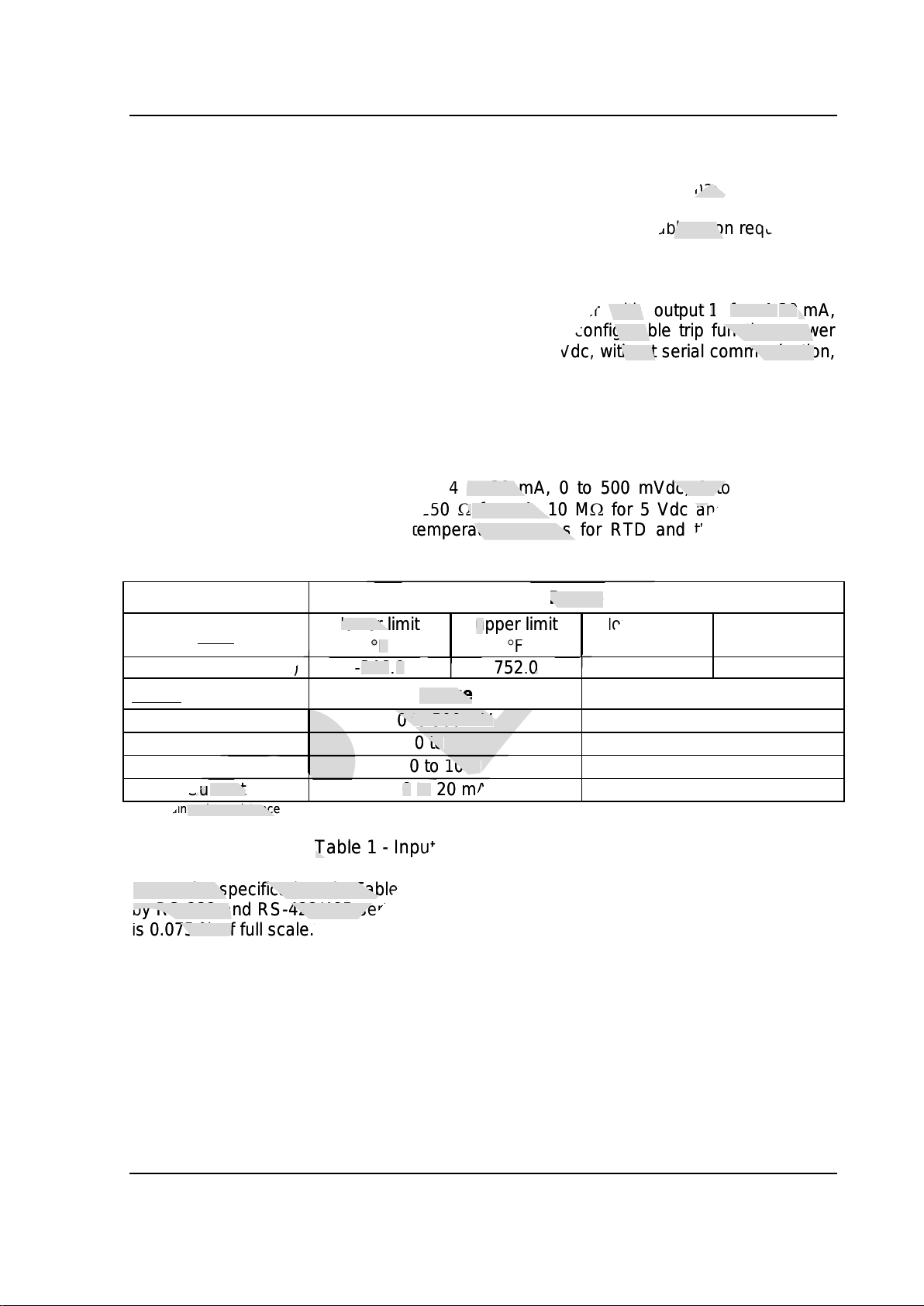
1.3 - Technical Specifications
Inputs:
Pt-100 RTD under DIN 43760, 4 to 20 mA, 0 to 500 mVdc, 1 to 5 Vdc, 0 to
10 Vdc. Input impedance of 250 for mA, 10 Mfor 5 Vdc and 2 Mabove
5 Vdc. Table 1 shows the temperature ranges for RTD and the resolution for
linear input sensors.
Input sensor Range
RTD
lower limit
F
upper limit
F
lower limit
C
upper limit
C
Pt-100 (2 or 3wires)
-346.0
752.0
-210.0
400.0*
Linear Range Resolution
Voltage
0to 500 mV
25
V
0to 5 V
250
V
0to 10 V
500
V
Current
0to 20 mA
1
A
(*)including wire resistance
Table 1 - Input Sensor Measuring Range
Note: The specifications in Table 1 refer to analog/digital conversion and are accessed
by RS-232 and RS-422/485 serial communication. For the analog outputs, the resolution
is 0.075 % of full scale.
presys
Module (if desired, specify such information so that all programming may be previously
presys
Module (if desired, specify such information so that all programming may be previously
Note: Any other desired software or hardware feature may be available upon request.
presys
Note: Any other desired software or hardware feature may be available upon request.
-Energy transmitter with output
presys
-Energy transmitter with output
1
presys
1
for 4-
presys
for 4-
20
presys
20
mA,
presys
mA,
not used, SPDT relay for use as alarm with configurable trip function, power
presys
not used, SPDT relay for use as alarm with configurable trip function, power
50/60Hz or 100-360 V
presys
50/60Hz or 100-360 V
dc
presys
dc
, without serial communication,
presys
, without serial communication,
RTD under DIN 43760, 4 to 20 mA, 0 to 500 mVdc, 1 to 5 Vdc, 0 to
presys
RTD under DIN 43760, 4 to 20 mA, 0 to 500 mVdc, 1 to 5 Vdc, 0 to
Vdc. Input impedance of 250
presys
Vdc. Input impedance of 250
presys
for mA, 10 M
presys
for mA, 10 M
presys
for 5 Vdc and 2 M
presys
for 5 Vdc and 2 M
5 Vdc. Table 1 shows the temperature ranges for RTD and the resolution for
presys
5 Vdc. Table 1 shows the temperature ranges for RTD and the resolution for
Range
presys
Range
presys
lower limit
presys
lower limit
presys
F
presys
F
upper limit
presys
upper limit
presys
F
presys
F
lower limit
presys
lower limit
presys
presys
presys
presys
presys
presys
presys
presys
s
presys
s
)
presys
)
-
presys
-
346
presys
346
.
presys
.
0
presys
0
752
presys
752
.
presys
.
0
presys
0
presys
presys
presys
presys
presys
presys
presys
presys
presys
presys
Range
presys
Range
presys
presys
presys
presys
presys
presys
Voltage
presys
Voltage
presys
0
presys
0
to 500 mV
presys
to 500 mV
presys
presys
presys
presys
presys
0
presys
0
to
presys
to
5 V
presys
5 V
presys
presys
presys
presys
0
presys
0
to
presys
to
10 V
presys
10 V
presys
presys
presys
presys
C
presys
C
u
presys
u
rrent
presys
rrent
0
presys
0
to
presys
to
20 mA
presys
20 mA
presys
presys
presys
presys
including wire resistance
presys
including wire resistance
presys
presys
presys
Table 1 - Input Sensor Measuring Range
presys
Table 1 - Input Sensor Measuring Range
Note: The specifications in Table 1 refer to analog/digital conversion and are accessed
presys
Note: The specifications in Table 1 refer to analog/digital conversion and are accessed
by RS-232 and RS-422/485 serial communication. For the analog outputs, the resolution
presys
by RS-232 and RS-422/485 serial communication. For the analog outputs, the resolution
is 0.075 % of full scale.
presys
is 0.075 % of full scale.

PRESYS Instruments TY-2090-Energy
Introduction
Page 4
Outputs:
Analog retransmitter output for 4-20 mA, 1 to 5 Vdc, 0 to 10 Vdc, use of
optional cards, with installation of up to two modules, galvanically isolated
(300 Vac)from inputs and power supply.
Alarm outputs for up to two SPDT relays and two SPST relays rated
3 A/220 Vac.
Logic Level, open collector transistor, 24 Vdc, 40 mA maximum with isolation.
Solid-state relay, rated 2A/250 Vac with isolation.
Serial Communication:
RS-232 or RS-422/485 with 50 Vdc isolation, as an optional module installed on
the CPU board. MODBUS®- RTU Communication Protocol.
Configuration:
Via RS-232,RS-422/485 serial communication or the MCY-20 Configuration
Module.
Scanning Time:
120 ms, standard.
Accuracy:
0.1 % of full scale for RTD, mA, mV and Vinputswith acquisition via RS-232
and RS-422/485 serial communication.
0.2 % of full scale for analog outputs and 750 maximum load.
Linearization:
0.1 Cfor RTD.
Square Root Extraction:
0.5 % of reading for input above 10 % of span.
0 to 5 % programmable cut-off.
Stability at ambient temperature:
0.005 % / ºC of span referred to 25 ºC ambient temperature for acquisition via
RS-232 and RS-422/485.
0.015 % /ºC of span referred to 25 ºC ambient temperature for analog outputs.
Power Supply:
75 to 264 Vac 50/60Hz or 100 to 360 Vdc (any polarity), 10 W nominal; 24 Vac/dc
(10 %); 12 Vdc (10 %).
2-Wire Transmitter Power Supply:
24 Vdc voltage and 50 mA maximum, isolated from outputs, with short-circuit
protection.
Operating ambient:
0 to 50ºC temperature and 90% maximum relative humidity.
Dimensions:
140 mm x 53 mm x 175 mm (HxWxD).
Weight:
0.5 kg nominal.
Warranty:
One year.
presys
Analog retransmitter output for 4-20 mA, 1 to 5 Vdc, 0 to 10 Vdc, use of
presys
Analog retransmitter output for 4-20 mA, 1 to 5 Vdc, 0 to 10 Vdc, use of
optional cards, with installation of up to two modules, galvanically isolated
presys
optional cards, with installation of up to two modules, galvanically isolated
two SPST relays rated
presys
two SPST relays rated
Logic Level, open collector transistor, 24 Vdc, 40 mA maximum with isolation.
presys
Logic Level, open collector transistor, 24 Vdc, 40 mA maximum with isolation.
Vdc isolation, as an optional module installed
presys
Vdc isolation, as an optional module installed
on
presys
on
- RTU Communication Protocol.
presys
- RTU Communication Protocol.
-422/485 serial communication or the MCY-20 Configurati
presys
-422/485 serial communication or the MCY-20 Configurati
on
presys
on
0.1 % of full scale for RTD, mA, mV
presys
0.1 % of full scale for RTD, mA, mV
and
presys
and
V
presys
V
input
presys
input
s
presys
s
with acquisition via
presys
with acquisition via
and RS-422/485 serial communication.
presys
and RS-422/485 serial communication.
0.2 % of full scale for analog outputs and 750
presys
0.2 % of full scale for analog outputs and 750
presys
maximum load.
presys
maximum load.
0.5 % of reading for input above 10 % of span.
presys
0.5 % of reading for input above 10 % of span.
0 to 5 % programmable cut-off.
presys
0 to 5 % programmable cut-off.
Stability at ambient temperature:
presys
Stability at ambient temperature:
0.005 % / ºC of span referred to
presys
0.005 % / ºC of span referred to
25
presys
25
ºC ambient temperature for acquisition via
presys
ºC ambient temperature for acquisition via
-232 and RS-422/485.
presys
-232 and RS-422/485.
0.015 %
presys
0.015 %
/
presys
/
ºC of span referred to 25 ºC ambient temperature for analog outputs.
presys
ºC of span referred to 25 ºC ambient temperature for analog outputs.
Power Supply:
presys
Power Supply:
75
presys
75
to
presys
to
264 Vac 50/60Hz or
presys
264 Vac 50/60Hz or
100
presys
100
to
presys
to
360 Vdc (any polarity), 10 W nominal; 24 Vac/dc
presys
360 Vdc (any polarity), 10 W nominal; 24 Vac/dc
(
presys
(
presys
10
presys
10
%); 12 Vdc (
presys
%); 12 Vdc (
presys
10
presys
10
%).
presys
%).
2-Wire Transmitter Power Supply:
presys
2-Wire Transmitter Power Supply:
24 Vdc voltage and 50 mA maximum, isolated from outputs, with short-circuit
presys
24 Vdc voltage and 50 mA maximum, isolated from outputs, with short-circuit
protection.
presys
protection.
Operating ambient:
presys
Operating ambient:
0 to 50ºC temperature and 90% maximum relative humidity.
presys
0 to 50ºC temperature and 90% maximum relative humidity.
Dimens
presys
Dimens
ion
presys
ion
s:
presys
s:
140 mm x 53 mm x 175 mm (HxWxD
presys
140 mm x 53 mm x 175 mm (HxWxD
Weight:
presys
Weight:
presys
0.5 kg nominal.
presys
0.5 kg nominal.
One year.
presys
One year.

PRESYS Instruments TY-2090-Energy
Installation
Page 5
2.0 - Installation
2.1 - Mechanical Installation
The TY-2090-Energy Transmitter can be mounted on a surface or on all types of
existing DIN rails,by means of an optional adapter, as illustrated in the figure below.
Fig. 2 - Dimensional drawing and detail of the adapter for DIN rail
2.2 - Electrical Installation
The TY-2090-Energy Transmitter may be powered up by voltage between 75 and
264 Vac or 100 to 360 Vdc, any polarity. Remember that the internal circuit is powered
whenever the instrument is connected to the external power supply.
Connections of process input and output signals should only be done with the
instrument turned off.
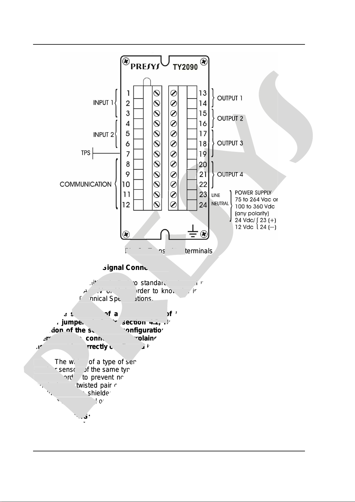
Figure 3 shows the instrument I/O terminal scheme with all designations for power
supply, grounding, communication and process input and output signals.
Signal wires must be kept far away from power supply wires.
Due to its metal case the instrument ground should be connected to earth
ground. Never connect the ground to the neutral terminal.
presys
-Energy Transmitter can be mounted on a surface or on all types of
presys
-Energy Transmitter can be mounted on a surface or on all types of
by means of an optional adapter, as illustrated in the figure below.
presys
by means of an optional adapter, as illustrated in the figure below.
presys
Fig. 2 - Dimensional drawing and detail of the adapter for DIN rail
presys
Fig. 2 - Dimensional drawing and detail of the adapter for DIN rail
2.2 - Electrical Installation
presys
2.2 - Electrical Installation
The TY-
presys
The TY-
2090
presys
2090
-Energy Transmitter may be powered
presys
-Energy Transmitter may be powered
264
presys
264
Vac or 100 to 360 Vdc, any polarity. Remember that the internal circuit is powered
presys
Vac or 100 to 360 Vdc, any polarity. Remember that the internal circuit is powered
whenever the instrument is connected to the external power supply.
presys
whenever the instrument is connected to the external power supply.
Connections of process input and output signals should only be
presys
Connections of process input and output signals should only be
instrument turned off.
presys
instrument turned off.
Figure 3 shows the instrument I/O terminal scheme with all designations for power
presys
Figure 3 shows the instrument I/O terminal scheme with all designations for power
supply, grounding, communication and process input and output signals.
presys
supply, grounding, communication and process input and output signals.
Signal wires must be kept far away from power supply wires.
presys
Signal wires must be kept far away from power supply wires.
Due to its metal case the instrument ground should be connected to earth
presys
Due to its metal case the instrument ground should be connected to earth
ground.
presys
ground.
Never
presys
Never
connect the ground to the neutral terminal.
presys
connect the ground to the neutral terminal.
PRESYS Instruments TY-2090-Energy
Installation
Page 6
Fig. 3 - Transmitter terminals
2.3 - Process Input Signal Connections
The Transmitter, in its two standard universal inputs, can be connected to 2 or
3-wire RTDs, mA, mV or V. In order to know the input sensor types refer to Table 1,
section 1.3 on Technical Specifications.
The selection of a certain type of input sensor is enabled by means of
internal jumpers (refer to section 4.2, Hardware Configuration) and by aproper
selection of the sensor in configuration time (refer to section 3.2, Configuration).
Therefore, the connections explained below will only become effective if the
instrument is correctly configured in terms of hardware and software.
The wiring of a type of sensor to input 1 does not restrict the simultaneous use of
another sensor, of the same type or different type, for input 2.
In order to prevent noise induction in the wire connecting the sensor to the I/O
terminal, use twisted pair cable and run the sensor connection wires through a metallic
conduit or use a shielded cable. Be sure to connect only one shielded wire end to the
negative I/O terminal or to the sensor ground, as outlined in the following items.
WARNING: GROUNDING TWO SHIELD WIRE ENDS MAY CAUSE NOISE IN
THE TRANSMITTER.
presys
presys
Fig. 3 - Transmitter terminals
presys
Fig. 3 - Transmitter terminals
Process Input Signal Connections
presys
Process Input Signal Connections
The Transmitter, in its two standard universal inputs, can be connected to 2 or
presys
The Transmitter, in its two standard universal inputs, can be connected to 2 or
3-wire RTDs, mA, mV or V. In order to know the input sensor types refer to Table 1,
presys
3-wire RTDs, mA, mV or V. In order to know the input sensor types refer to Table 1,
section 1.3 on Technical Specifications.
presys
section 1.3 on Technical Specifications.
The selection of a certain type of input sensor is enabled by means of
presys
The selection of a certain type of input sensor is enabled by means of
internal jumpers (refer to section 4.2, Hardware Configuration) and by
presys
internal jumpers (refer to section 4.2, Hardware Configuration) and by
selection of the sensor in configuration time (refer to section 3.2, Configuration).
presys
selection of the sensor in configuration time (refer to section 3.2, Configuration).
Therefore, the connections explained below will only become effective if the
presys
Therefore, the connections explained below will only become effective if the
instrument is correctly configured in terms of hardware and software.
presys
instrument is correctly configured in terms of hardware and software.
The wiring of a type of sensor to input 1 does not restrict the simultaneous use of
presys
The wiring of a type of sensor to input 1 does not restrict the simultaneous use of
another sensor, of the same type or different type, for input 2.
presys
another sensor, of the same type or different type, for input 2.
In order to prevent noise induction in the wire connecting the sensor to the I/O
presys
In order to prevent noise induction in the wire connecting the sensor to the I/O
terminal, use twisted pair cable and run the sensor connection wires through a metallic
presys
terminal, use twisted pair cable and run the sensor connection wires through a metallic
presys
conduit or use a shielded cable. Be sure to connect only one shielded wire end to the
presys
conduit or use a shielded cable. Be sure to connect only one shielded wire end to the
negative I/O terminal or to the sensor ground, as outlined in the following items.
presys
negative I/O terminal or to the sensor ground, as outlined in the following items.
WARNING: GROUNDING TWO SHIELD WIRE ENDS MAY CAUSE NOISE IN
presys
WARNING: GROUNDING TWO SHIELD WIRE ENDS MAY CAUSE NOISE IN
THE TRANSMITTER.
presys
THE TRANSMITTER.

PRESYS Instruments TY-2090-Energy
Installation
Page 7
2.3.1 - RTD Connections
The RTD can be connected with 2, 3 or 4 wires. All connection types are shown in
figure 4.
For 2-wire RTD, connect the RTD between I/O terminals 1 and 3 to use input 1, or
to terminals 4 and 6 to use input 2, as illustrated in figure 4.
For 3-wire RTD, connect the RTD in the same way as described for a 2-wire
connection, and connect the third wire for RTD compensation to terminal 2 in case of
input 1, and to terminal 5 in case of input 2, see figure 4.
A 4-wire RTD is connected to the Transmitter in the same way as a 3-wire RTD,
except that the fourth wire is disregarded and left disconnected, see figure 4.
A 3-wire RTD provides greater accuracy than a 2-wire RTD.
The RTD wiring should be of the same material, length and gauge to ensure
proper resistance compensation of connecting wires. The maximum resistance of
connecting wires is 10 per wire. The minimum gauge should be 18 AWG for distances
up to 50 meters and 16 AWG for distances greater than 50 meters.
Fig. 4 - RTD Connection
presys
The RTD can be connected with 2, 3 or 4 wires. All connection types are shown in
presys
The RTD can be connected with 2, 3 or 4 wires. All connection types are shown in
For 2-wire RTD, connect the RTD between I/O terminals 1 and 3 to use input 1, or
presys
For 2-wire RTD, connect the RTD between I/O terminals 1 and 3 to use input 1, or
For 3-wire RTD, connect the RTD in the same way as described for a 2-wire
presys
For 3-wire RTD, connect the RTD in the same way as described for a 2-wire
connection, and connect the third wire for RTD compensation to terminal 2 in case of
presys
connection, and connect the third wire for RTD compensation to terminal 2 in case of
A 4-wire RTD is connected to the Transmitter in the same way as a 3-wire RTD,
presys
A 4-wire RTD is connected to the Transmitter in the same way as a 3-wire RTD,
except that the fourth wire is disregarded and left disconnected, see figure 4.
presys
except that the fourth wire is disregarded and left disconnected, see figure 4.
A 3-wire RTD provides greater accuracy than a 2-wire RTD.
presys
A 3-wire RTD provides greater accuracy than a 2-wire RTD.
presys
The RTD wiring should be of the same material, length and gauge to ensur
presys
The RTD wiring should be of the same material, length and gauge to ensur
proper resistance compensation of connecting wires. The maximum resistance of
presys
proper resistance compensation of connecting wires. The maximum resistance of
per wire. The minimum gauge should be 18 AWG for distances
presys
per wire. The minimum gauge should be 18 AWG for distances
up to 50 meters and 16 AWG for distances greater than 50 meters.
presys
up to 50 meters and 16 AWG for distances greater than 50 meters.
presys
presys
PRESYS Instruments TY-2090-Energy
Installation
Page 8
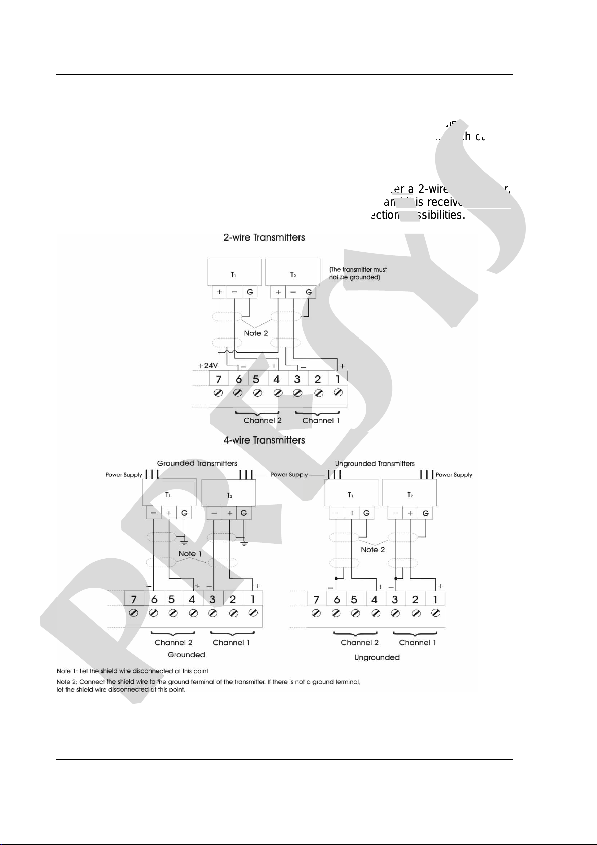
2.3.2 - Current Input
A standard current source of 4 to 20 mA can be applied to terminals 1 (+) and
3 (-) in case of input 1, and to terminals 4 (+) and 6 (-) in case of input 2. Such current
can be generated by a transmitter with external power supply.
When using the intrument’s internal 24 Vdc source to power a 2-wire transmitter,
the current is received only by terminal 1 (+) in case of input 1, and it is received only by
terminal 4 (+) in case of input 2. Figure 5 illustrates both connection possibilities.
Fig. 5 - Current Source Connection
presys
terminals 1 (+) and
presys
terminals 1 (+) and
terminals 4 (+) and 6 (-) in case of input 2. Such current
presys
terminals 4 (+) and 6 (-) in case of input 2. Such current
internal 24 Vdc source to power a 2-wire transmitter,
presys
internal 24 Vdc source to power a 2-wire transmitter,
the current is received only by terminal 1 (+) in case of input 1, and it is received only by
presys
the current is received only by terminal 1 (+) in case of input 1, and it is received only by
terminal 4 (+) in case of input 2. Figure 5 illustrates both connection possibilities.
presys
terminal 4 (+) in case of input 2. Figure 5 illustrates both connection possibilities.
presys
presys
PRESYS Instruments TY-2090-Energy
Installation
Page 9
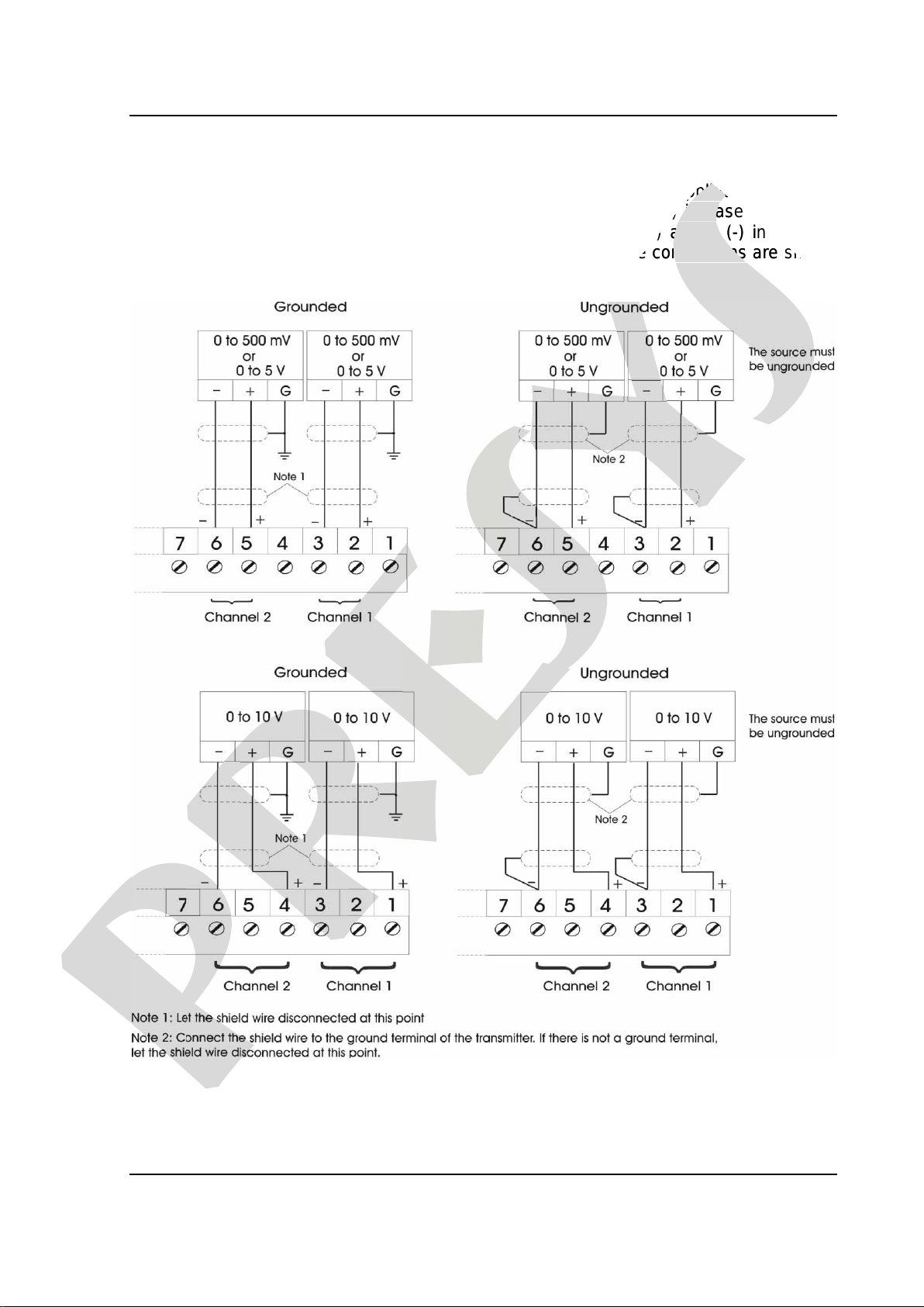
2.3.3 - Voltage Inputs
Voltages from 0 to 500 mVdc or from 0 to 5 Vdc must be applied to terminals
2 (+) and 3 (-) in case of input 1, and to terminals 5 (+) and 6 (-) in case of input 2.
Voltages from 0 to 10 Vdc should be applied to terminals 1 (+) and 3 (-) in case of
input 1, and to terminals 4 (+) and 6 (-) in case of input 2. These connections are shown
in figure 6.
Fig. 6 - Voltage Source Connection
presys
Voltages from 0 to 500 mVdc or from 0 to 5 Vdc must be applied to terminals
presys
Voltages from 0 to 500 mVdc or from 0 to 5 Vdc must be applied to terminals
terminals 5 (+) and 6 (-) in case of input 2.
presys
terminals 5 (+) and 6 (-) in case of input 2.
terminals 1 (+) and 3 (-) in case of
presys
terminals 1 (+) and 3 (-) in case of
presys
terminals 4 (+) and 6 (-) in case of input 2. These connections are shown
presys
terminals 4 (+) and 6 (-) in case of input 2. These connections are shown
presys

PRESYS Instruments TY-2090-Energy
Installation
Page 10
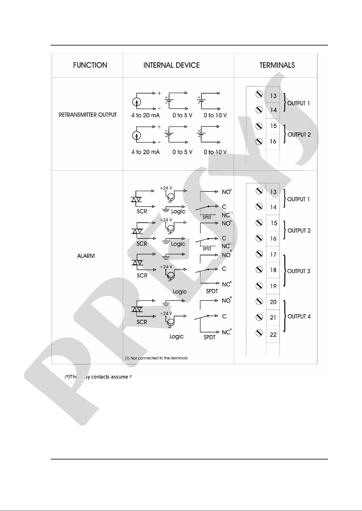
2.4 - Output Connections
The Transmitter, in its most complete version, can be provided with up to four
output signals: output 1, output 2, output 3 and output 4. Outputs 1 and 2 are used as
retransmission outputs or alarm outputs. Outputs 3 and 4 are used only as alarm
outputs.
In case of outputs 1 and 2, there are six different output types, which can be
obtained between I/O terminals: retransmission output (4 to 20 mA, 0 to 5 Vdc or
0 to 10 Vdc), SPST relay, open collector voltage and solid-state relay.
For outputs 3 and 4 there are three different output types: SPDT relay, open
collector voltage and solid-state relay. Figure 7 shows the Transmitter outputs.
Notice that the I/O terminals will only show output signals if the
corresponding optional module is installed and the output is correctly configured.
In case of analog outputs, refer to sections 3.2 on Configuration and 4.4 on
Optional Module Connection for details on installation and configuration of
optional modules.
The state of the relay contacts illustrated in Figure 7 assume that the
instrument is powered off. When powered on, the status (open or closed) depends
on the SAFE configuration and if the instrument is or is not in alarm condition.
Table 2 summarizes the state of the relay contacts in all conditions.
Power
Supply SAFE Alarm
Condition
Relay 1
Terminals
13 and 14
Relay 2
Terminals
15 and 16
Relay 3
Terminals
17 and 18
Relay 4
Terminals
20 and 21
OFF
---
---
OPEN
OPEN
OPEN
OPEN
ON
YES
NO
CLOSED
CLOSED
CLOSED
CLOSED
ON
YES
YES
OPEN
OPEN
OPEN
OPEN
ON
NO
NO
OPEN
OPEN
OPEN
OPEN
ON
NO
YES
CLOSED
CLOSED
CLOSED
CLOSED
Table 2 - Relays State in All Possible Conditions of the Instrument
The factory setting for the relay is SAFE = "NO" for trip relays and
SAFE = "YES" for the other relays.
presys
The Transmitter, in its most complete version, can be provided with up to four
presys
The Transmitter, in its most complete version, can be provided with up to four
output signals: output 1, output 2, output 3 and output 4. Outputs 1 and 2 are used as
presys
output signals: output 1, output 2, output 3 and output 4. Outputs 1 and 2 are used as
retransmission outputs or alarm outputs. Outputs 3 and 4 are used only as alarm
presys
retransmission outputs or alarm outputs. Outputs 3 and 4 are used only as alarm
In case of outputs 1 and 2, there are six different output types, which can be
presys
In case of outputs 1 and 2, there are six different output types, which can be
obtained between I/O terminals: retransmission output (4 to 20 mA, 0 to 5 Vdc or
presys
obtained between I/O terminals: retransmission output (4 to 20 mA, 0 to 5 Vdc or
Vdc), SPST relay, open collector voltage and solid-state relay.
presys
Vdc), SPST relay, open collector voltage and solid-state relay.
For outputs 3 and 4 there are three different output types: SPDT relay, open
presys
For outputs 3 and 4 there are three different output types: SPDT relay, open
collector voltage and solid-state relay. Figure 7 shows the Transmitter outputs.
presys
collector voltage and solid-state relay. Figure 7 shows the Transmitter outputs.
Notice that the I/O terminals will only show output signals if the
presys
Notice that the I/O terminals will only show output signals if the
corresponding optional module is installed and the output is correctly configured.
presys
corresponding optional module is installed and the output is correctly configured.
In case of analog outputs, refer to sections 3.2
presys
In case of analog outputs, refer to sections 3.2
on
presys
on
Configuration and 4.4
presys
Configuration and 4.4
on
presys
on
Optional Module Connection for details on installation and configuration of
presys
Optional Module Connection for details on installation and configuration of
The state of the relay contacts illustrated in Figure 7 assume that the
presys
The state of the relay contacts illustrated in Figure 7 assume that the
powered off. When power
presys
powered off. When power
ed
presys
ed
on, the status (open or closed) depends
presys
on, the status (open or closed) depends
on the SAFE configuration and if the instrument is or is not in alarm condition.
presys
on the SAFE configuration and if the instrument is or is not in alarm condition.
Table 2 summarizes the state of the relay contacts in all conditions.
presys
Table 2 summarizes the state of the relay contacts in all conditions.
Alarm
presys
Alarm
Condition
presys
Condition
Rel
presys
Rel
ay 1
presys
ay 1
Terminals
presys
Terminals
13 and 14
presys
13 and 14
Relay 2
presys
Relay 2
Terminals
presys
Terminals
15 and 16
presys
15 and 16
Relay 3
presys
Relay 3
presys
presys
presys
presys
presys
presys
presys
presys
presys
presys
presys
---
presys
---
OPEN
presys
OPEN
OPEN
presys
OPEN
presys
presys
presys
presys
presys
presys
presys
presys
presys
presys
YES
presys
YES
NO
presys
NO
CLOSED
presys
CLOSED
CLOSED
presys
CLOSED
presys
presys
presys
presys
presys
presys
presys
presys
presys
presys
YES
presys
YES
YES
presys
YES
OPEN
presys
OPEN
OPEN
presys
OPEN
presys
presys
presys
presys
presys
presys
presys
presys
presys
presys
NO
presys
NO
NO
presys
NO
OPEN
presys
OPEN
presys
presys
presys
presys
presys
presys
presys
presys
presys
presys
NO
presys
NO
YES
presys
YES
CL
presys
CL
OSED
presys
OSED
presys
presys
presys
presys
presys
presys
presys
presys
presys
presys
presys
presys
presys
presys
presys
presys
presys
presys
presys
presys
Table 2 - Relays State in All Possible Conditions of the Instrument
presys
Table 2 - Relays State in All Possible Conditions of the Instrument
The factory setting for the relay is SAFE = "NO" for trip relays and
presys
The factory setting for the relay is SAFE = "NO" for trip relays and
SAFE = "YES" for the other relays.
presys
SAFE = "YES" for the other relays.
PRESYS Instruments TY-2090-Energy
Installation
Page 11
(*)The relay contacts assume that the instrument is powered off.
Fig. 7 - Output Connections
presys
presys
(*)The relay contacts assume that the instrument is
presys
(*)The relay contacts assume that the instrument is

PRESYS Instruments TY-2090-Energy
Installation
Page 12
2.5 - Connection Diagram
presys
presys

PRESYS Instruments TY-2090-Energy
Installation
Page 13
2.6 - Communication
The TY-2090-Energy Transmitter can communicate with computers via RS-232 or
RS-422/485 provided the optional communication module is installed and the proper
communication parameters are configured via software.
Specific information about communication and signal connection can be found in
the Communication Manual and on section 5.0 - MODBUS Communication.
2.7 - Engineering Units
A label with several Engineering Units is supplied with each transmitter. Choose
the one corresponding to the variable shown in the configurator MCY-20 of the
transmitter.
presys
-Energy Transmitter can communicate with computers via RS-232 or
presys
-Energy Transmitter can communicate with computers via RS-232 or
-422/485 provided the optional communication module is installed and the proper
presys
-422/485 provided the optional communication module is installed and the proper
Specific information about communication and signal connection can be found in
presys
Specific information about communication and signal connection can be found in
presys
the Communication Manual and on section 5.0 - MODBUS Communication.
presys
the Communication Manual and on section 5.0 - MODBUS Communication.
A label with several Engineering Units is supplied with each transmitter. Choose
presys
A label with several Engineering Units is supplied with each transmitter. Choose
presys
the one corresponding to the variable shown in the configurator MCY-20 of the
presys
the one corresponding to the variable shown in the configurator MCY-20 of the

PRESYS Instruments TY-2090-Energy
Operation
Page 14
3.0 - Operation
3.1 - Normal Operation
The TY-2090-Energy Transmitter has two operation modes: normal operation and
operation in configuration time.
In normal operation the Transmitter retransmits the process variable to a remote
point either through its two analog outputs 1 and 2, or via RS-232 or RS-422/485
communication. The analog outputs 1 and 2 can retransmit input 1 as well as input 2.
The two analog outputs can even retransmit the same input. Moreover, the Transmitter
checks the alarm conditions and activates the alarm outputs 3 and 4 if it is the case.
The Transmitter has a portable configuration unit, MCY-20, which is connected to
it by means of a DB-25 connector, as illustrated in figure 8 below.
Fig. 8 - MCY-20 Portable Configuration Module
When the MCY-20 Configuration Module is connected to the Transmitter under
normal operation, the instrument begins to function as a transmitter and as a process
monitor as well, through the Module display.
Under configuration time operation mode the user, through the MCY-20
Configuration Module, selects and assigns values to the parameters which regulate the
Transmitter functioning, when in normal operation. Such parameters are, among others,
alarm setpoint values, retransmission output range, etc.
presys
-Energy Transmitter has two operation modes: normal operation and
presys
-Energy Transmitter has two operation modes: normal operation and
In normal operation the Transmitter retransmits the process variable to a remote
presys
In normal operation the Transmitter retransmits the process variable to a remote
point either through its two analog outputs 1 and 2, or via RS-232 or RS-422/485
presys
point either through its two analog outputs 1 and 2, or via RS-232 or RS-422/485
communication. The analog outputs 1 and 2 can retransmit input 1 as well as input 2.
presys
communication. The analog outputs 1 and 2 can retransmit input 1 as well as input 2.
The two analog outputs can even retransmit the same input. Moreover, the Transmitter
presys
The two analog outputs can even retransmit the same input. Moreover, the Transmitter
checks the alarm conditions and activates the alarm outputs 3 and 4 if it is the case.
presys
checks the alarm conditions and activates the alarm outputs 3 and 4 if it is the case.
The Transmitter has a portable configuration unit, MCY-20, which is connected to
presys
The Transmitter has a portable configuration unit, MCY-20, which is connected to
it by means of a DB-25 connector, as illustrated in figure 8 below.
presys
it by means of a DB-25 connector, as illustrated in figure 8 below.
presys
Fig. 8 - MCY-20 Portable Configuration Module
presys
Fig. 8 - MCY-20 Portable Configuration Module
When the MCY-20 Configuration Module is connected to the Transmitter under
presys
When the MCY-20 Configuration Module is connected to the Transmitter under
normal operation, the instrument begins to function as a transmitter and as a process
presys
normal operation, the instrument begins to function as a transmitter and as a process
monitor as well, through the Module display.
presys
monitor as well, through the Module display.
Under configuration time operation mode the user, through the MCY-
presys
Under configuration time operation mode the user, through the MCY-
Configuration Module, selects and assigns values to the parameters which regulate the
presys
Configuration Module, selects and assigns values to the parameters which regulate the
Transmitter functioning, when in normal operation. Such parameters are, among others,
presys
Transmitter functioning, when in normal operation. Such parameters are, among others,
PRESYS Instruments TY-2090-Energy
Operation
Page 15
The normal operation mode, in which the Transmitter operates most of the time,
will be called level zero. At this level, the keys on the panel of the MCY-20 Configuration
Module have the following functions:
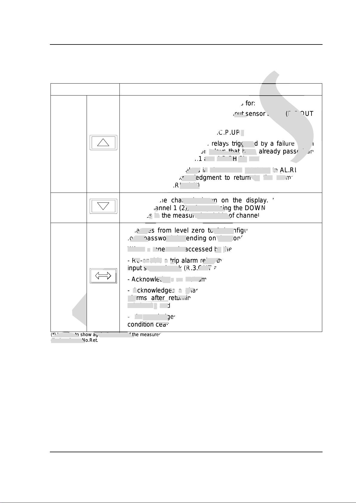
Key Function
UP
Presents the corresponding mnemonics for:
- Trip alarm relays disabled due to input sensor break (R.3.OUT
and R.4.OUT);
- Instrument power-up event (AC.P.UP);
-Channels associated with relays triggered by a failure alarm
(AL.CH.1 and AL.CH.2) or relays that have already passed an
alarm condition (AC.CH.1 and AC.CH.2); and
- Latch configured relays in alarm state (AL.RL.1 to AL.RL.4) or
which require acknowledgment to return to the normal state
(AC.RL.1 to AC.RL.4) (*)
DOWN Changes the channel shown on the display. If the display
shows channel 1 (2), after pressing the DOWN key, the display
changes to the measured variable of channel 2 (1).
ENTER
Changes from level zero to 1 (configuration mode) or asks
for a password depending on the configuration.
When a mnemonic accessed by the UP key is presented:
-Re-enable atrip alarm relay that has been disabled due to an
input sensor break (R.3.OUT and R.4.OUT);
-Acknowledgesan instrument power-up event (AC.P.UP);
-Acknowledges a channel associated with relays with failure
alarms after returning to the normal condition (AC.CH.1 or
AC.CH.2); and
-Acknowledgesa latch configured relay after the alarm
condition ceased (AC.RL.1 to AC.RL.4).
(*) In order to show again the value of the measured variable, continue to press the UP key. If there is no latched relay, the
display shows No.Ret.
presys
presys
corresponding mnemonics
presys
corresponding mnemonics
for
presys
for
:
presys
:
due to input sensor break
presys
due to input sensor break
(
presys
(
R.3.OUT
presys
R.3.OUT
(AC.
presys
(AC.
P.UP
presys
P.UP
);
presys
);
with
presys
with
relay
presys
relay
s
presys
s
triggered
presys
triggered
by a
presys
by a
fail
presys
fail
ure
presys
ure
alarm
presys
alarm
or
presys
or
relays that
presys
relays that
have already passed
presys
have already passed
an
presys
an
H
presys
H
.1
presys
.1
and
presys
and
AC.C
presys
AC.C
H
presys
H
.2);
presys
.2);
and
presys
and
r
presys
r
elays
presys
elays
in
presys
in
alarm state
presys
alarm state
(AL.RL.1
presys
(AL.RL.1
t
presys
t
o
presys
o
AL.RL.4) o
presys
AL.RL.4) o
acknowledgment to return to
presys
acknowledgment to return to
the
presys
the
normal state
presys
normal state
AC.RL.4) (*)
presys
AC.RL.4) (*)
presys
presys
Changes the channel shown on
presys
Changes the channel shown on
the
presys
the
display. If the display
presys
display. If the display
channel 1 (2), after pressing the DOWN key, the display
presys
channel 1 (2), after pressing the DOWN key, the display
changes
presys
changes
to
presys
to
the measured variable of channel 2 (1).
presys
the measured variable of channel 2 (1).
presys
presys
presys
presys
presys
Changes from level zero to 1 (configuration mode) or asks
presys
Changes from level zero to 1 (configuration mode) or asks
for a password depending on the configuration
presys
for a password depending on the configuration
When
presys
When
a
presys
a
mnemonic accessed
presys
mnemonic accessed
by
presys
by
the UP key
presys
the UP key
-
presys
-
Re
presys
Re
-
presys
-
en
presys
en
able
presys
able
a
presys
a
trip alarm
presys
trip alarm
relay that has been disabled due to
presys
relay that has been disabled due to
input sensor break
presys
input sensor break
(
presys
(
R.3.OUT and R.4.OUT
presys
R.3.OUT and R.4.OUT
-
presys
-
Ac
presys
Ac
knowledge
presys
knowledge
s
presys
s
an
presys
an
instrument
presys
instrument
-
presys
-
Ac
presys
Ac
knowledge
presys
knowledge
s
presys
s
a
presys
a
channel associated with relays with failure
presys
channel associated with relays with failure
alarms after returning to the normal cond
presys
alarms after returning to the normal cond
AC.CH.2
presys
AC.CH.2
);
presys
);
and
presys
and
-
presys
-
Ac
presys
Ac
knowledge
presys
knowledge
s
presys
s
condition
presys
condition
ceased
presys
ceased
presys
presys
presys
presys
presys
presys
presys
presys
presys
presys
(*) In order to show again the value of the measured variable, continue to press the UP key. If there is
presys
(*) In order to show again the value of the measured variable, continue to press the UP key. If there is
display shows No.Ret.
presys
display shows No.Ret.

PRESYS Instruments TY-2090-Energy
Operation
Page 16
In the operation mode it is possible to re-enable the trip alarms configured with failure
manual reset (see section 3.2 - Configuration: Level 3- Alarms) by following the procedure
below:
(i) The display shows a blinking B.OUT.1 / 2 mnemonic (for channel 1 / 2 with RTD
input) or the BRK.1 /2 mnemonic (for 4-20 mA current input), indicating that the sensor is
broken and the TRIP alarms are disabled;
(ii) Reconnect the sensor to the instrument terminals;
(iii) The display shows alternatively the indication value and the RL.OUT mnemonic
(relays 3 and/or 4 disabled);
(iv) Enable the relays with TRIP alarms according to the steps below:
1. Press the UP key during the exhibition of the process variable in order to
show the mnemonic of the disabled relay (R.3.OUT or R.4.OUT);
2. Press ENTER;
3. The R.3.OUT or R.4.OUT mnemonic disappears;
4. The display shows the next disabled relay mnemonic, if present, or the
mnemonics for the power up event (AC.P.UP), failure alarm (AC.CH.1 or
AC.CH.2) or for the relay alarms (AC.RL.1 to AC.RL.4) which require
acknowledgement in order to return to normal state (latch condition).
In order to pass to the next mnemonic without re-enabling the trip relay or
acknowledging an alarm relay under latch condition, one must press the UP key once again.
After all available mnemonics are shown, the display returns to the process variable
indication.
Note: If both relays 3 and 4 are disabled, relay 3 will be re-enabled first (by pressing ENTER
for the R.3.OUT mnemonic) and then relay 4 is re-enabled (ENTER for the R.4.OUT
mnemonic).
presys
(i) The display shows a blinking B.OUT.1 / 2 mnemonic (for channel 1 / 2 with RTD
presys
(i) The display shows a blinking B.OUT.1 / 2 mnemonic (for channel 1 / 2 with RTD
mA current input), indicating that the sensor is
presys
mA current input), indicating that the sensor is
(iii) The display shows alternatively the indication value and the RL.OUT mnemonic
presys
(iii) The display shows alternatively the indication value and the RL.OUT mnemonic
(iv) Enable the relays with TRIP alarms according to the steps below:
presys
(iv) Enable the relays with TRIP alarms according to the steps below:
Press the UP key during the exhibition of the process variable in order to
presys
Press the UP key during the exhibition of the process variable in order to
show the mnemonic of the disabled relay (R.3.OUT or R.4.OUT
presys
show the mnemonic of the disabled relay (R.3.OUT or R.4.OUT
);
presys
);
The R.3.OUT or R.4.OUT mnemonic disappears;
presys
The R.3.OUT or R.4.OUT mnemonic disappears;
The display shows the next disabled relay mnemonic, if present, or the
presys
The display shows the next disabled relay mnemonic, if present, or the
mnemonics for the power up event (AC.P.UP), failure alarm (AC.CH.1 or
presys
mnemonics for the power up event (AC.P.UP), failure alarm (AC.CH.1 or
AC.CH.2) or for the relay alarms (AC.RL.1 to AC.RL.4) which require
presys
AC.CH.2) or for the relay alarms (AC.RL.1 to AC.RL.4) which require
acknowledgement in order to return to normal state (latch condition).
presys
acknowledgement in order to return to normal state (latch condition).
In order to pass to the next mnemonic without re-enabling the trip relay or
presys
In order to pass to the next mnemonic without re-enabling the trip relay or
acknowledging an alarm relay under latch condition, one must press the UP key once again.
presys
acknowledging an alarm relay under latch condition, one must press the UP key once again.
presys
After all available mnemonics are shown, the display returns to the process variable
presys
After all available mnemonics are shown, the display returns to the process variable
If both relays 3 and 4 are disabled, relay 3 will be re-enabled first (by pressing ENTER
presys
If both relays 3 and 4 are disabled, relay 3 will be re-enabled first (by pressing ENTER
presys
for the R.3.OUT mnemonic) and then relay 4 is re-enabled (ENTER for the R.4.OUT
presys
for the R.3.OUT mnemonic) and then relay 4 is re-enabled (ENTER for the R.4.OUT
PRESYS Instruments TY-2090-Energy
Operation
Page 17
3.2 - Configuration
To have access to the configuration mode, one should provide the password
configured with the purpose of preventing unauthorized people from altering the critical
parameters of the process.
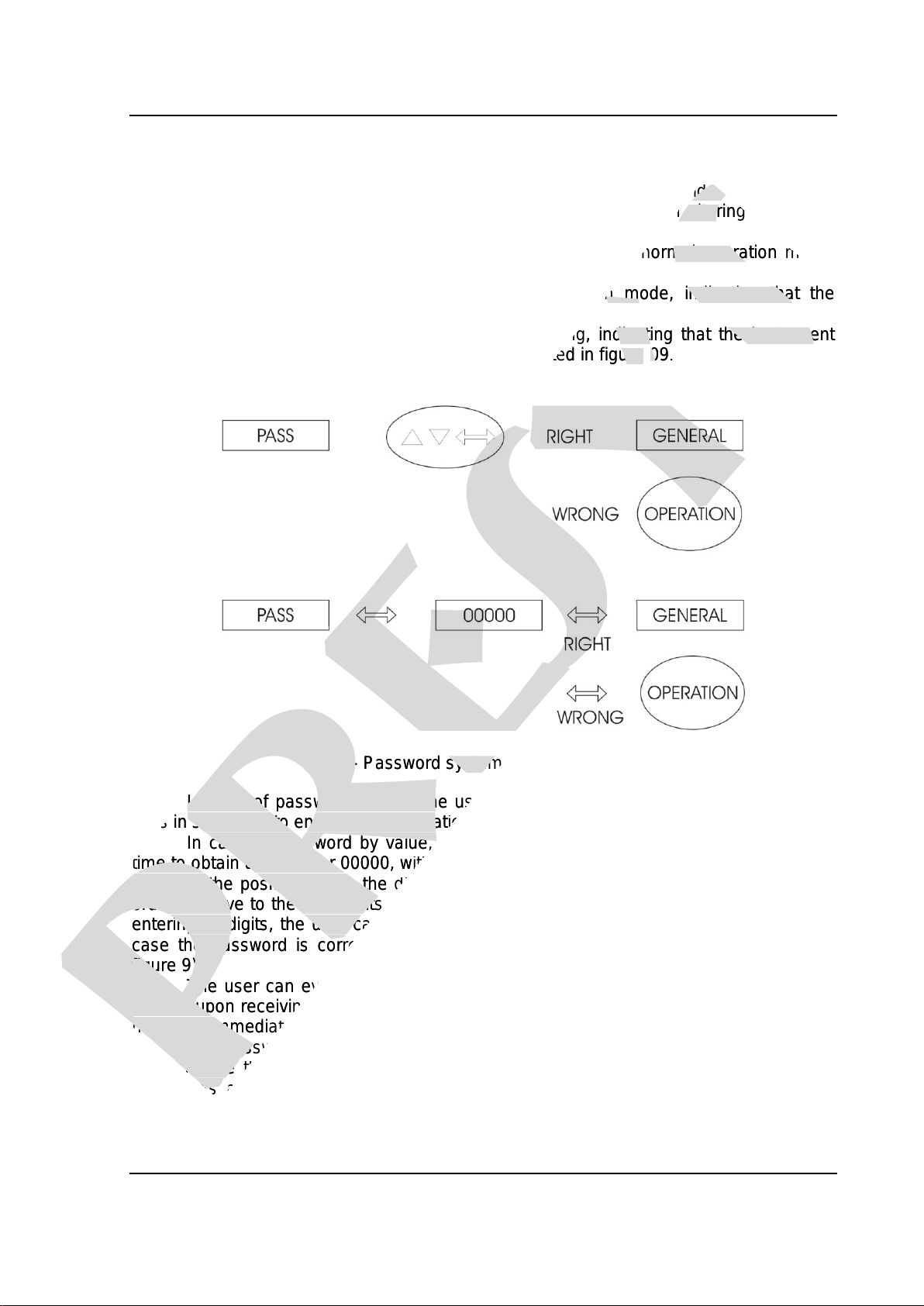
Therefore, whenever the ENTER key is pressed under normal operation mode,
one of the following cases might occur:
i) Enter directly into level 1 (GENERAL) of configuration mode, indicating that the
instrument was not configured with a password system.
ii) The Module display shows the PASSWORD warning, indicating that the instrument
has a password system by key or by value, as illustrated in figure 09.
Fig. 9 - Password system by key and by value
In case of password by key, the user should press the UP, DOWN and ENTER
keys in sequence to enter the configuration levels.
In case of password by value, the user should press the ENTER key a second
time to obtain the number 00000, with the last digit blinking on the right. The blinking digit
indicates the position where the digit of a 4-digit number will be entered by the user. In
order to move to the next digits on the left, the user should press the ENTER key. After
entering all digits, the user can press the ENTER key once more to switch to level 1 in
case the password is correct, otherwise the system reverts to normal operation (see
figure 9).
The user can even select both password systems, by key and by value. In such
case, if upon receiving a request for a password the user enters a wrong key sequence,
he will be immediately reverted to password by value.
The password can be a number chosen by the user (customized) or the number
2090. Notice that in case of password by value the number 2090 is always enabled,
serving as a help to the user in case he forgets his password. In order to enter a
password number or any other parameter value, the user can use the front Module keys,
which have the following functions:
presys
To have access to the configuration mode, one should provide the password
presys
To have access to the configuration mode, one should provide the password
configured with the purpose of preventing unauthorized people from altering the critical
presys
configured with the purpose of preventing unauthorized people from altering the critical
Therefore, whenever the ENTER key is pressed under normal operation mode,
presys
Therefore, whenever the ENTER key is pressed under normal operation mode,
i) Enter directly into level 1 (GENERAL) of configuration mode, indicating that the
presys
i) Enter directly into level 1 (GENERAL) of configuration mode, indicating that the
ii) The Module display shows the PASSWORD warning, indicating that the instrument
presys
ii) The Module display shows the PASSWORD warning, indicating that the instrument
has a password system by key or by value, as illustrated in figure
presys
has a password system by key or by value, as illustrated in figure
09
presys
09
.
presys
.
presys
Fig. 9 - Password system by key and by value
presys
Fig. 9 - Password system by key and by value
In case of password by key, the user should press the UP, DOWN and ENTER
presys
In case of password by key, the user should press the UP, DOWN and ENTER
keys in sequence to enter the configuration levels.
presys
keys in sequence to enter the configuration levels.
In case of password by value, the user should press the ENTER key a second
presys
In case of password by value, the user should press the ENTER key a second
time to obtain the number 00000, with the last digit blinking on the right. The blinking digit
presys
time to obtain the number 00000, with the last digit blinking on the right. The blinking digit
indicates the position where the digit of a 4-digit number will be entered by the user. In
presys
indicates the position where the digit of a 4-digit number will be entered by the user. In
presys
order to move to the next digits on the left, the user should press the ENTER key. After
presys
order to move to the next digits on the left, the user should press the ENTER key. After
entering all digits, the user can press the ENTER key once more to switch to level 1 in
presys
entering all digits, the user can press the ENTER key once more to switch to level 1 in
case the password is correct, otherwise the system reverts to normal operation (see
presys
case the password is correct, otherwise the system reverts to normal operation (see
figure 9).
presys
figure 9).
The user can even select both password systems, by key and by value. In such
presys
The user can even select both password systems, by key and by value. In such
case, if upon receiving a request for a password the user enters a wrong key sequence,
presys
case, if upon receiving a request for a password the user enters a wrong key sequence,
he will be immediately reverted to password by value.
presys
he will be immediately reverted to password by value.
The password can be a number chosen by the user (customized) or the number
presys
The password can be a number chosen by the user (customized) or the number
presys
2090. Notice that in case of password by value the number 2090 is always enabled,
presys
2090. Notice that in case of password by value the number 2090 is always enabled,
serving as a help to the user in case he forgets his password. In order to enter a
presys
serving as a help to the user in case he forgets his password. In order to enter a
Other manuals for TY-2090
1
Table of contents
Other Presys Transmitter manuals


