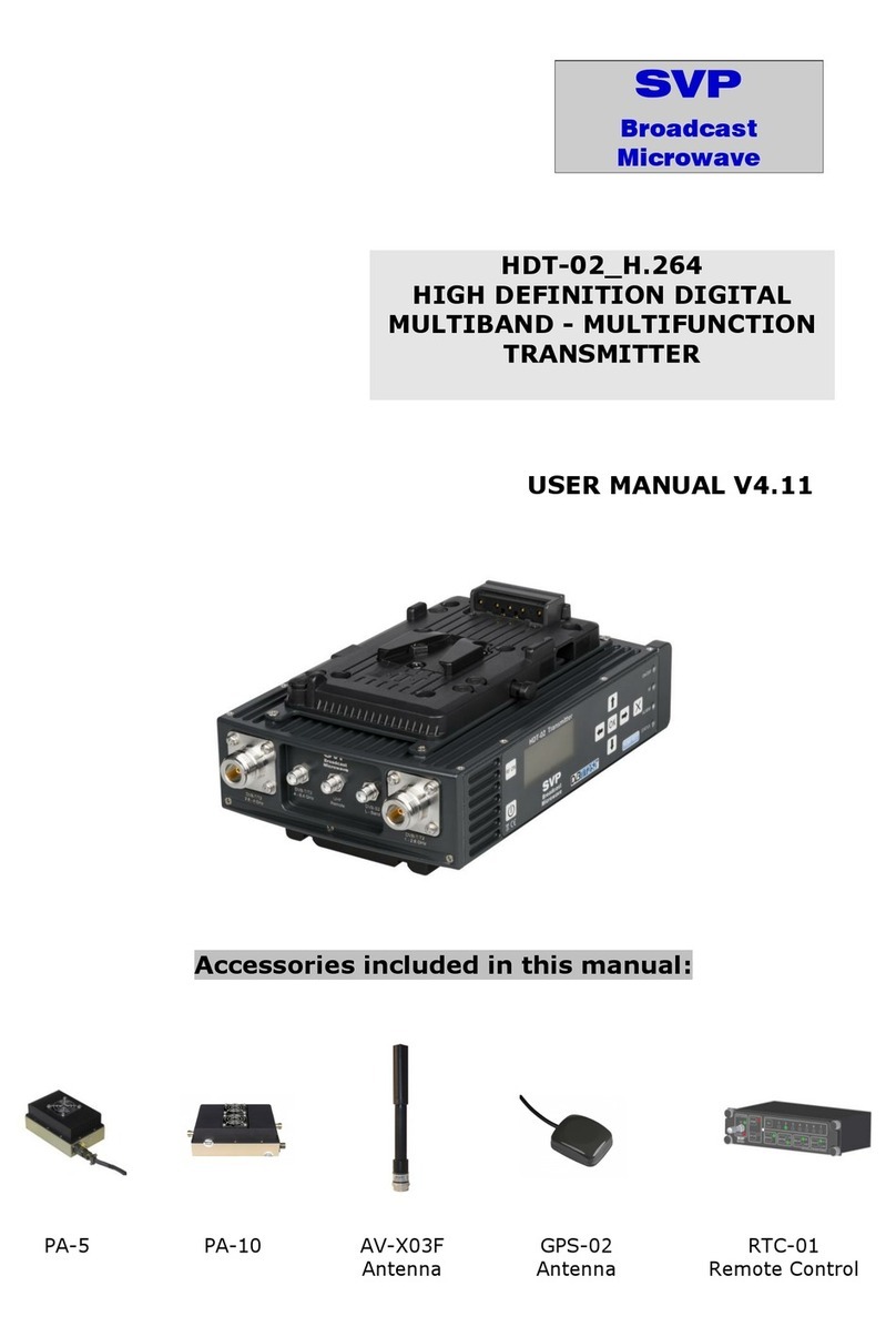
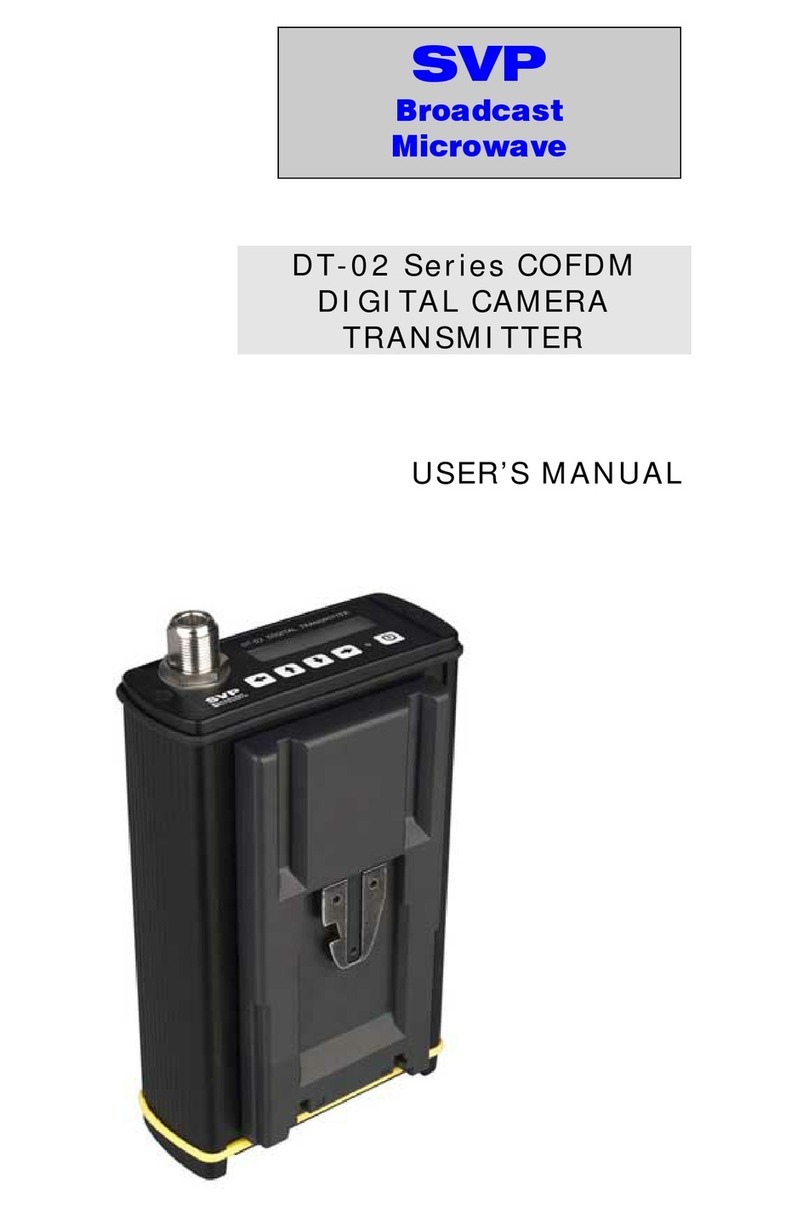
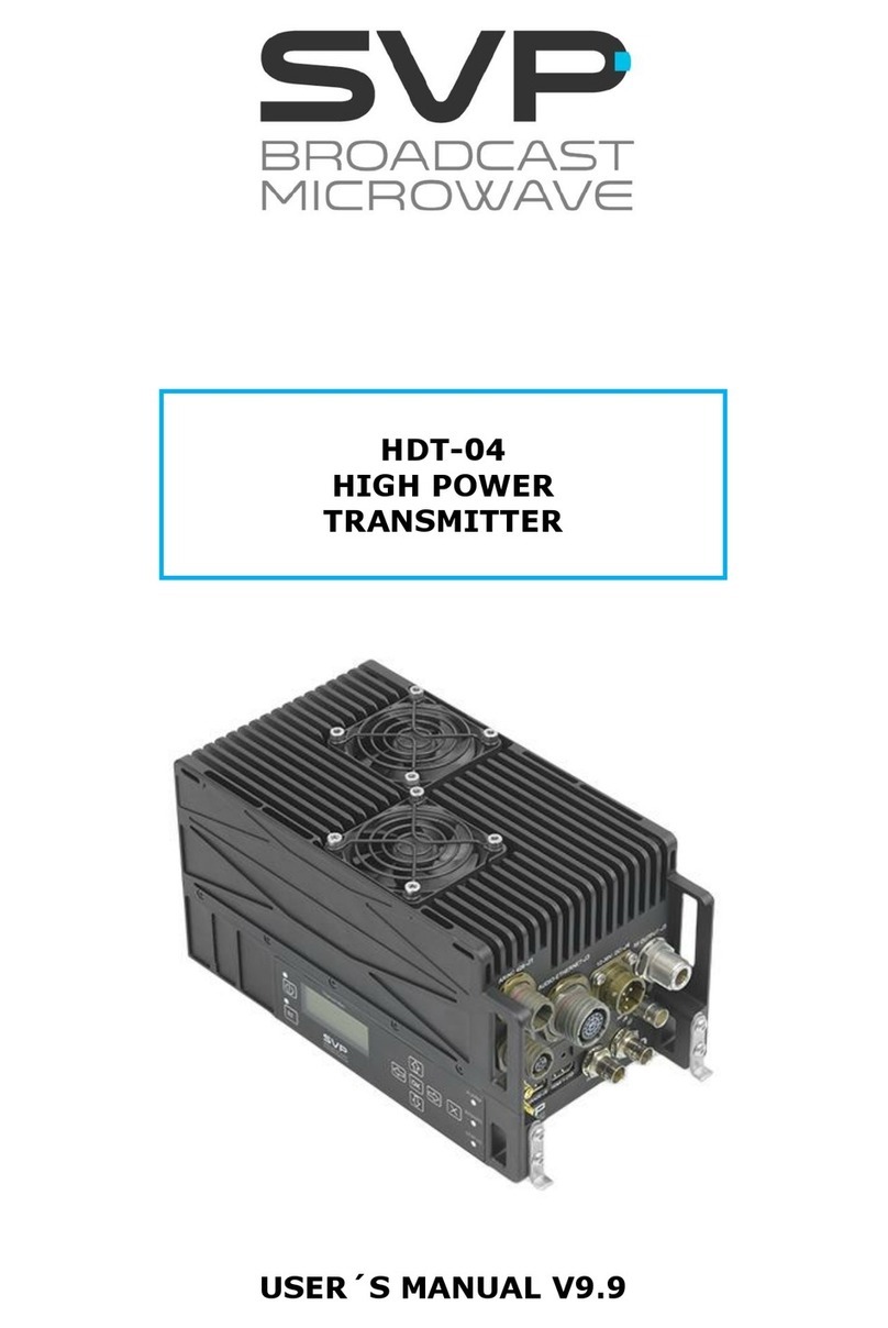
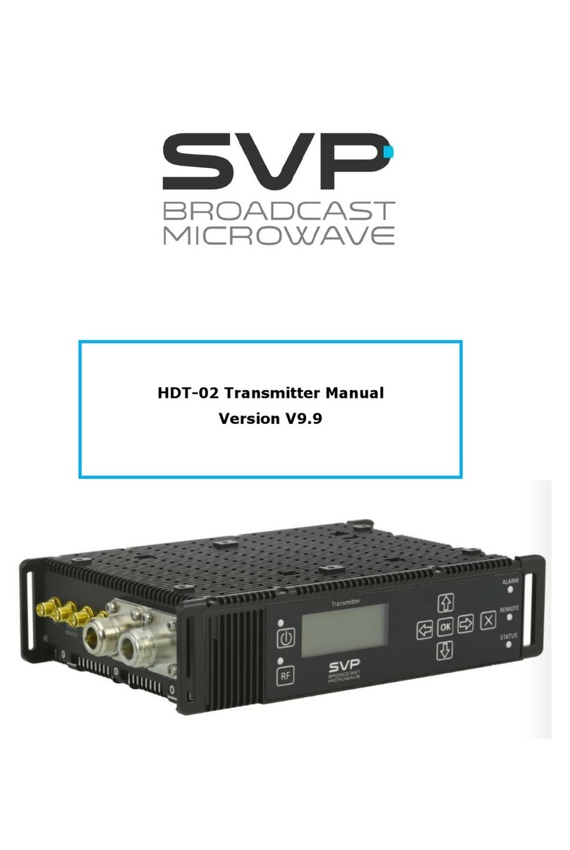
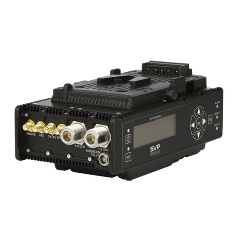
SVP HDT-02 User manual

SVP
Broadcast
Microwave
HIGH DEFINITION DIGITAL
CAMERA TRANSMITTER
HDT-02
USER MANUAL V1.0

1
HDT-02 High Definition Digital Camera Transmitter
USER’S MANUAL V1.0:
Contents
Chapter 1: Introduction
This first chapter provides a general description of the High definition HDT-
02 camera transmitter
Chapter 2: Technical features
This second part offers a detailed description of each connection available
on the HDT-02 series camera transmitter. Inputs, outputs, power supply,
and transmitter’s physical and environmental characteristics are also
provided.
Chapter 3: Transmitter operation and Menus
This third part provides the user with all necessary information to control
and operate the equipment properly. It is detailed the function of each
button on the keyboard. It is also explained how the information is shown
on the display, transmitter’s menus, alarms, etc.
Chapter 4: Applications
In this last chapter some interesting applications for the HDT-02 transmitter
system are shown.

2
HDT-02 High Definition Digital Camera Transmitter
USER’S MANUAL V1.0:
Dear customer,
We would like to thank you for selecting this equipment and welcome you to
the SVP’s products user’s growing family.
We are sure that the addition of this equipment to your existing installation
will cause you nothing but satisfaction.
Please read these instructions carefully, and keep them at hand in case you
have to refer to them.

3
HDT-02 High Definition Digital Camera Transmitter
USER’S MANUAL V1.0:
Important Notes
1. The HDT-02 series COFDM High Definition camera transmitter is
completely compatible with the DVB-T Standard, included in the
European Standard ETSI EN300744
2. The HDT-02 digital camera transmitter applies a MPEG-2 compression to
either composite video, SD-SDI or HD-SDI input signals. An MPEG-1
layer 2 compression is applied to the corresponding 4 analogue audio
channels or digital SDI embedded audio signals. The resulting
multiplexed signal is transmitted using COFDM modulation system.
3. The HDT-02 transmitter operates in either 2GHz or 3GHz frequency
bands from 2.0 to 2.5GHz, from 2.2 to 2.6GHz and from 3.4 to 3.7GHz
respectively.
4. Equipment’s maximum output power is 100mWatt.
5. Special care should be taken with SDI cables, quality and length are very
important specially when HD-SDI signals are transmitted.
6. It is not recommended to switch the HDT-02 camera transmitter on
without antenna or load.
7. When 720p HD-SDI signal is transmitted transmitter’s output bitrate
should be higher than 8Mbps. On the other hand, if 1080i HD-SDI signal
is transmitted, transmitter’s output bitrate should be higher than
16Mbps. If the transmitter is not properly configured (modulation, FEC
and guard interval) minimum bitrate alarm will occur.
8. When an audio channel is not used it should be disabled.
9. The HDT-02’s keypad is locked when it is not operated for 3 minutes. To
unlock it right arrow button should be pressed for several seconds.
10.Only authorized personnel should open the product and any repair or
warranty will be invalidated if the seals are broken.

4
HDT-02 High Definition Digital Camera Transmitter
USER’S MANUAL V1.0:
Main Index
CHAPTER 1: Introduction
CHAPTER2: Technical Features
1Main characteristics.......................................................................6
2Connections .................................................................................8
2.1Power supply ..........................................................................9
2.2VIDEO/SD-SDI/HD-SDI/ASI Input..............................................9
2.3Audio inputs .........................................................................10
2.4RF output/Antena .................................................................. 11
CHAPTER3: Transmitter operation and Menus
1Display and LED ......................................................................... 12
2Front panel ................................................................................14
2.1ON/OFF Button...................................................................... 14
2.2Left Button ........................................................................... 15
2.3Right Button .........................................................................15
2.4Up and Down button ..............................................................15
3Menus .......................................................................................16
4Transmitter operation .................................................................. 18
4.1Change of a parameter/ SETUP Menu .......................................19
4.2Monitoring a parameter/MONITOR menu...................................21
5Alarms ......................................................................................22
5.1Input signal type alarm. .........................................................22
5.2Minimum bitrate alarm ...........................................................22
5.3ASI Overflow alarm................................................................ 23
5.4Transmission frequency alarm .................................................23
5.5Power supply voltage alarm ....................................................24
5.6Temperature alarm................................................................24
6HD Upgrade ...............................................................................25
CHAPTER4: Applications
1Introduction ...............................................................................26
2Applications example ciones .........................................................27
2.1Iphone application .................................................................27

5
HDT-02 High Definition Digital Camera Transmitter
USER’S MANUAL V1.0:
Chapter 1: Introduction
The HDT-02 camera transmitter can broadcast High Definition (HD) and
Standard Definition (SD) signals using COFDM (Coded Orthogonal
Frequency Division Multiplexing) modulation in 2K mode.
HD technology allows the delivery of High Definition images with excellent
resolution and detail, SDI signals of up to 1.5Gbps.
Input video signals, composite video, SD-SDI or HD-SDI are MPEG-2
encoded, together with 4 analogue audios or 4 digital audios embedded on
the SDI signal. The resulting transport Stream is COFDM 2K mode
modulated to make the transmission of all this information possible. MPEG-2
coding can be done using different profiles: MP@HL, MP@ML and 422@ML.
Minimum latency when super low delay option is selected is 45ms.
The HDT-02 transmitter has a Transport Stream ASI input so it can be used
as a repeater.
It is available in 3 different frequency ranges: from 2.0 to 2.5GHz, from 2.2
to 2.6GHz and from 3.4 to 3.7GHz. Maximum output power is 100mWatt.
High quality components have been used to achieve the best output signal
quality.
Transmitter system operation is very easy. It has a display and a keyboard
which make possible the configuration and monitorization of every
parameter of the equipment.
The equipment is fed with DC power supply from 10 to 36V. It can be
powered through DC power supply connector or through the battery mount.
Its excellent design, mechanical and electronic assembly make the HDT-02
a robust and reliable solution.
Figure 1.1 HDT-02 camera transmitter

6
HDT-02 High Definition Digital Camera Transmitter
USER’S MANUAL V1.0:
Chapter 2: Technical Features
1Main characteristics
RF Section:
Frequency range:
2GHz A Model: 2.0 to 2.5GHz
2GHz B Model: 2.2 to 2.6GHz
3GHz Model: 3.4 to 3.7GHz
Output power level:
Maximum: 20dBm (100mW)
Programmable: 1 dB steps from 14dBm
Frequency tuning step : 500KHz
Video Section:
Video Formats
PAL: 4:2:0 (720x576)/4:2:2(720x625)
NTSC: 4:2:0 (720x480)/4:2:2(720x525)
720P (1280x720): 4:2:0/4:2:2
Frame rate: 59.94/50/29.97/25/23.97Hz
1080i (1920x1080): 4:2:0/4:2:2
Frame rate: 29.97/25
Video Inputs: Composite video/ SD-SDI/HD-SDI
ASI Input : EN50083-9
Composite video Input: 75Ω, 1Vpp, NTSC/PAL
SD/HD SDI Input: SMPTE 259M/292M (270Mbps – 1.5Gbps)
Audio Section:
Audio channel number: 2 pairs stereo, 4 mono
Audio input type: Analogue/Embedded
Input level selectable: Micro /line (Analogue)
Phantom voltage: Selectable (only with micro level)
Maximum input level: +15dBm
Signal to noise ratio: >70dB
Input impedance: 20KΩ
Audio coding: MPEG-2 Layer1
Audio simple rate: 48 KHz
Audio Bitrate: 128, 192, 256, 384 KHz

7
HDT-02 High Definition Digital Camera Transmitter
USER’S MANUAL V1.0:
Coding section
Coding profiles: MP@ML (4:2:0): 1 a 15Mbps
422@ML (4:2:2) 3 a 31.65Mbps
MP@HL
Delay: Standard mode, super low delay mode
Latency: Super low delay mode: 45 – 54ms
Modulation section
Modulation system: COFDM DVB-T, 2K mode
Constellation types: QPSK, 16QAM, 64QAM
FEC – Convolutional code: 1/2, 2/3, 3/4, 5/6, 7/8
Guard interval: 1/4, 1/8, 1/16, 1/32
Bitrate: 4.98 – 31.65Mbps
Bandwidth: 5, 6, 7, 8MHz
Power supply:
Input range: 10 a 36V (Extended range)
Consumption: 18Watt
Connections:
RFAntenna: NFemale
Composite video/SDI/ASI: 75ΩBNC
Audios: 2 x 5 pin Lemo 0B
DC power supply: 4 pin Lemo 1B
Battery adapter: IDC V Clip or Anton Bauer
Physical features:
Dimensions:
Width: 110mm
Height: 45mm
Depth: 175mm
Weight: 0.95Kg
Operation temperature: -10 a 45ºC
Audio and power supply cables are supplied with the HDT-02 camera
transmitter

8
HDT-02 High Definition Digital Camera Transmitter
USER’S MANUAL V1.0:
2Connections
Every connection of the HDT-02 camera transmitter is on the rear panel,
except for the RF antenna connection that is on the front panel.
All the input/output connections of the camera transmitter are shown in the
figure below:
Figure 2.1 HDT-02 Connections
The following figures show the HDT-02’s front and rear panel. Connections
mentioned in the upper figure are shown below.
Figure 2.2 HDT-02’s front panel
Figure 2.3 HDT-02’s rear panel
Technical features of each connection are described on the following
sections.

9
HDT-02 High Definition Digital Camera Transmitter
USER’S MANUAL V1.0:
2.1 Power supply
The equipment is powered by a DC source from 10 to 36V, extended range.
The DC power supply is connected to the equipment via a 4 pin Lemo 1B
connector.
Table 2.1 Power supply connection technical features
Item Features
Connector label POWER D.C.
Connector type 4 pin Lemo 1B
Input voltage range 10-36 V.
Consumption 18 Watt.
The pinout of the power supply connector is:
1 and 2 pins => ground
3 and 4 pins => from 10 to 36V
2.2 VIDEO/SD-SDI/HD-SDI/ASI Input
All input signal types share same isolated 75ΩBNC connector. This
connector is placed on transmitter’s rear panel.
SD-SDI digital video input is compatible with SMPTE-259 Standard and HD-
SDI digital video input signal type is SMPTE 292 compliant.
It is important that 75Ωconnectors are used. This is because the female
input connector of the HDT-02 unit may be damaged and because an
impedance mismatch will occur.
Table 2.2 Video input signal connection features
Item Features
Connector label VIDEO/SDI/ASI
Input signal type VIDEO SDI
Connector type Isolated BNC female
Impedance 75Ω
Input level 1 Vpp over 75Ω800mVpp nominal ±10%
Return losses >25dB @ 5MHz > 15 dB, 5-1500 MHz
Standard PAL/NTSC SMPTE-259M and SMPTE-272M
SMPTE-292M and SMPTE-299M
Video coding standard MPEG-2 (ISO/IEC 13818-2)

10
HDT-02 High Definition Digital Camera Transmitter
USER’S MANUAL V1.0:
Table 2.3 DVB-ASI Transport Stream Connection features
Item Features
Connector label VIDEO/SDI/ASI
Connector type Isolated BNC female
Impedance 75Ω
Standard EN50083-9
Maximum Bitrate 31.65 Mbit/s
2.3 Audio inputs
The HDT-02 has 4 analogue audio input signals that are inserted in pairs via
two 5 pin Lemo 0B connectors on equipment’s rear panel. Only balanced
audio signals are accepted. Audio cables are supplied with the equipment.
Input audio signal level can be micro or line and it is selectable from the
front panel of the equipment. When micro input level is selected phantom
voltage can be enabled or disabled.
The HDT-02 also accepts four digital audio signals embedded on the SD-SDI
and HD-SDI video signals. The audio signals must be compliant with
SMPTE-272M standard when embedded on SD-SDI video signal and with
SMPTE-299M standard when embedded on HD-SDI video signal.
Table 2.4 Audio connection’s technical features
Item Features
Audio channel number 4
Connector labels AUDIO 1
AUDIO 2
Connector type 5 pin Lemo 0B
Impedance 20KΩ
Sampling frequency 48 KHz
Bit rate 128, 192, 256,o 384 Kbit/s
selectable
Coding standard MPEG-1 L2
Signal to noise ratio >70dB
The pinout of the audio connector is:
Pin 3 => Ground
Pins 1 and 2 => Audio L signals
Pins 4 and 5 => Audio R signals

11
HDT-02 High Definition Digital Camera Transmitter
USER’S MANUAL V1.0:
2.4 RF output/Antena
The antenna is directly connected to the female N-type connector on the
front panel of the HDT-02 camera transmitter.
Table 2.5 RF output characteristics
Item Features
Connector label RF ANTENNA
Connector type N female
Output frequency range 2.0-2,5GHz
2.2-2.6GHz
3.4-3.7GHz
Impedance 50Ω
Output power Maximum: 100 mWatt

12
HDT-02 High Definition Digital Camera Transmitter
USER’S MANUAL V1.0:
Chapter 3: Transmitter operation and
menus
This third chapter provides the user with all necessary information to
control, configure and operate the equipment properly.
1Display and LED
To turn the equipment on and off, keep ON/OFF button pressed for several
seconds. When the equipment is turned on, the display will show the start-
up message (model and version of the equipment) for two seconds, and
then it will display the main screen.
In the main screen the following parameters are displayed:
Frequency (MHz)
Input selection (Composite video, SDI or DVB-ASI Transport Stream)
Input signal detection (presence/absence)
Audios status indication (enabled/disabled)
Input video signal type: SD Standard definition or HD High definition
If ASI input signal is selected, the input bitrate is displayed
If composite video or SDI input signal is selected the video encoding
profile used is displayed (MPEG-2 4:2:2 or MPEG-2 4:2:0)
Latency (Standard delay or Super Low Delay)
Modulation Scheme (QPSK, 16QAM o 64QAM)
FEC (1/2, 2/3, 3/4, 5/6 o 7/8)
Guard Interval (1/4, 1/8, 1/16 o 1/32)
Transmitted bitrate (Mpbs)
Figure 1.1 HDT-02’s front panel/ Main screen
Frequency
Input
Selection
Audio
Status Input
Type Profile
Latency
Output
bitrate
Guard
Interval
FEC
Modulation
Scheme

13
HDT-02 High Definition Digital Camera Transmitter
USER’S MANUAL V1.0:
The LED next to the ON/OFF button provides the following
information:
If the Led is off the equipment is not being fed
The Led flashes red when there is power into the equipment but it is
turned off
The Led lights up in green when the equipment is turned on
If the equipment is locked the Led flashes in green
The Led flashes green and red if the HDT-02 is alarmed.
When the input signal type is configured to be composite video a “V” is
displayed in the input signal selection. On the other hand, if the selected
input signal type is SDI an “S” is displayed in the main screen.
Figure 1.2 HDT-02’s Main screen. Selected input signal: SDI
The audio status indicator shows an “A” when the selected input audio
signals are analogue. On the other hand, if the audios are embedded in the
SDI input signal the equipment should be configured to extract the audios
from the SDI signal. In this case an “E” is displayed in the audio status
indicator.
If the selected input signal type is composite video the audios cannot be
configured as embedded as they cannot be extracted from the SDI signal.
When the selected input type is ASI, the main screen shows:
Input Bitrate
Signal presence/absence
Figure 1.3 Main screen. Selected input type: ASI Transport Stream

14
HDT-02 High Definition Digital Camera Transmitter
USER’S MANUAL V1.0:
If the input bitrate is higher than the transmitted bitrate, there is an
overflow and the input bitrate value blinks in the main screen showing an
alarm.
Configured modulation scheme, FEC, guard interval and output bitrate are
displayed on the second line of the main screen.
2Front panel
The HDT-02 camera transmitter is configured following a menus structure
on the display. The front panel has 5 buttons to enter and exit the
equipment’s control menus and submenus and to navigate through them.
Functions of each button are detailed in the following sections.
Figure 2.1 HDT-02’s front panel
2.1 ON/OFF Button
To turn the equipment on and off, keep this button pressed for several
seconds. When the equipment is turned on, the display will show the start-
up message (model and version of the equipment) for two seconds, and
then it will display the main screen.
If the power fails while the equipment is operating, it will restart
automatically when the power returns, not being necessary to press the
on/off button again.
Figure 2.2 ON/OFF button

15
HDT-02 High Definition Digital Camera Transmitter
USER’S MANUAL V1.0:
2.2 Left Button
This button is used to:
Enter and exit equipment’s main menu
Exit equipment’s submenus
Once the parameter to change has been selected, it is used to move the
cursor towards the digit immediately on the left
2.3 Right Button
This buttons has several functions:
Enter submenus and parameters to be changed.
Every parameter except for the frequency and the PIDs has limited
options. Once a parameter has been selected, pressing this button the
selected option changes. For example the modulation scheme has 3
options: QPSK, 16QAM or 64QAM. Input video type has also 3 options:
composite video, SDI or Transport Stream. Pressing right button a
change from one option to another occurs.
To introduce the frequency, the PIDs values, the parameter is selected
and then right button has to be pressed to be able to change the
frequency value. Once the parameter value has been changed, to store
de value, right button has to be pressed again.
Unlock. If the equipment has not being operated for 3 minutes the
keypad is locked. The Led flashes in green. To unlock the keypad the
right arrow has to be pressed until a “bip” sound indicates that is has
been unlocked.
2.4 Up and Down button
The up and down arrow buttons allow navigation in the main menu and
the rest of submenus. Using this buttons the submenu to be entered or
the parameter to be changed is selected. Once selected, to enter it right
button has to be pressed.
This buttons are also used to change the frequency and PID parameter’s
values. Pressing up and down arrows the value of those parameters can
be changed, increased or decreased respectively.
Figure 2.3 Left, Up, Down and Right buttons

16
HDT-02 High Definition Digital Camera Transmitter
USER’S MANUAL V1.0:
3Menus
To enter the main menu of this equipment left button should be pressed.
Two options are displayed: Monitor and Setup. To choose one or the other
up and down arrows are used. Once one is selected right button should be
pressed.
Monitor submenu allows the operator to check transmitter’s configuration, it
does not allow the change of any parameter. Setup submenu allows the
operator to change transmitter’s parameters and to configure them.
The greyed out parameters are not selectable with the current version.
Table 3.1Setup menu options
Menu Line Options Comments
1. Frequency 2.0 to 2.5GHz
2.2 to 2.6GHz
3.4 to 3.7GHz
Transmission frequency configuration
Frequency range depends on HDT-02 model
If configured frequency is out of equipment’s
frequency range the transmitter adjusts it to
nearest frequency inside allowed frequency band
2. Tx Power 100mWatt (20dBm)
Low (14dBm)
Adjustable (1dB Steps)
Transmitted output power
3. Input. Sel Video/SDI/ASI Input signal type selection.
The transmitter detects automatically SDI input
signal type SD-SDI o HD-SDI
4. Modul QPSK/16QAM/64QAM Modulation scheme selection
5. FEC 1/2,2/3, 3/4, 5/6, 7/8 FEC Selection
6. Guard 1/4, 1/8, 1/16, 1/32 Guard Interval selection
7. Bandwidth 5/6/7/8MH Channel bandwidth selection
8.TS
Parameters
Video PID
Audio1 PID
Audio2 PID
PMT PID
PCR PID
Prog. Number
Transport Stream parameters configuration, PID
number.
9. Video options Profile: 4:2:0/4:2:2
Delay: Standard/SuperLD
Coding parameters configuration

17
HDT-02 High Definition Digital Camera Transmitter
USER’S MANUAL V1.0:
10 Audio
Options
Input Sel: Analog/SDI_embd
Audio DID: G1/G2/G3/G4
Audio1: Enable/Disable
Audio1 Rate: 128K/192K/
256K/384K
Audio1L: Line/mic/mic_phan
Audio1R: Line/mic/mic_phan
Audio2: Enable/Disable
Audio2 Rate: 128K/192K/
256K/384K
Audio2L: Line/mic/mic_phan
Audio2R: Line/mic/mic_phan
Audio channels configuration
11. Test
Generator
Video generator
12. HD Enable NO/YES
Key:XXXXXXXXXX
Code: to be provided by SVP
HD upgrade submenu
Contact SVP
Table 3.2 Monitor Menu options
Función Opciones Comentarios
Frequency 2.0 to 2.5GHz
2.2 to 2.6GHz
3.4 to 3.7GHz
Configured transmission frequency (in MHz)
Tx Power High (20dBm)
Low (14dBm)
Adjustable: other value
Selected output power
Input. Sel Video/SDI/ASI Input type
Modul QPSK/16QAM/64QAM Modulation scheme
FEC 1/2,2/3, 3/4, 5/6, 7/8 FEC
Guard 1/4, 1/8, 1/16, 1/32 Guard Interval
Bandwidth 5/6/7/8MH Channel bandwidth
PLL Lock Yes/No PLL status
TS Parameters Video PID
Audio1 PID
Audio2 PID
PMT PID
PCR PID
Prog. Number
PID values
Tx. BitR: 4.95 – 31.65Mpbs Transmitted bitrate. Depends on modulation
scheme, FEC and guard interval used.

18
HDT-02 High Definition Digital Camera Transmitter
USER’S MANUAL V1.0:
Video options Profile: 4:2:0/4:2:2
Delay: Standard/SuperLD
Info: Input signal format
Aspect Ratio: 4:3/16:9
Video present: Yes/No
Input signal and coding info.
Audio Options Input Sel: Analog/SDI_embd
Audio DID: G1:767/G2:509
G3:507/G4:761
Audio1: Enable/Disable
Audio1 Rate: 128K/192K/
256K/384K
Audio1L: Line/mic/mic_phan
Audio1R: Line/mic/mic_phan
Audio2: Enable/Disable
Audio2 Rate: 128K/192K/
256K/384K
Audio2L: Line/mic/mic_phan
Audio2R: Line/mic/mic_phan
Audio channel configuration.
ASI Input ASI Present: Yes/No
Bitrate
Overflow: Yes/No
Packet format:188/204
ASI input characteristics
Test Gen Video generator information
Voltage 10-36V Power supply information
Temperatura ºC Transmitter Works properly in -10 to +45ºC range
Rev X.XX Software version
SN XXXXXXXXX Serial number
4Transmitter operation
Transmitter system operation is very easy. It has a display and a keyboard
which make possible the configuration from the front panel. The main
screen shows all the necessary information to check transmitter’s status.
To enter the main menu of this equipment left button should be pressed.
Two options are displayed: Monitor and Setup. To choose one or the other
up and down arrows are used. Once one is selected, right button should be
pressed.

19
HDT-02 High Definition Digital Camera Transmitter
USER’S MANUAL V1.0:
Figure 4.1 Main menu.
4.1 Change of a parameter/ SETUP Menu
When operating the transmitter, two parameter types can be observed:
1. Parameters with limited options (2 or 3 options)
2. Parameters with multiple options
To modify a limited options parameter, it must be selected using up and
down arrows. Once selected, pressing right button the operator navigates
through the different available options. When the desired option is on the
display the modification, parameter value change, has been done.
Modulation scheme parameter example:
Once the parameter has been selected, as right button is pressed, the
operator navigates through the different options for the modulations
scheme parameter: QPSK, 16QAM or 64QAM.
Figure 4.2 Modulation scheme selection: QPSK
Figure 4.3 Modulation scheme selection: 16QAM
Other manuals for HDT-02
1
Table of contents
Other SVP Transmitter manuals
Popular Transmitter manuals by other brands

GP:50
GP:50 311 installation manual

Creative
Creative BT-W3X quick start guide

Critical Environment Technologies
Critical Environment Technologies cGas Detector Operation manual

Monacor
Monacor AV-410SET instruction manual

Audiovox
Audiovox Auto Security SS91 Programming guide

Evikon
Evikon PluraSens E2418DF user manual