Priefert Q36-98 User manual

www.priefert.com 800-527-8616
Q36-98 Solar Box
Installation Instructions
AI_Q36-98_v2-0223
IMPORTANT:
Battery must be connected for
operation! Remove cover to connect power supply.
See page 4 of Assembly Instructions.
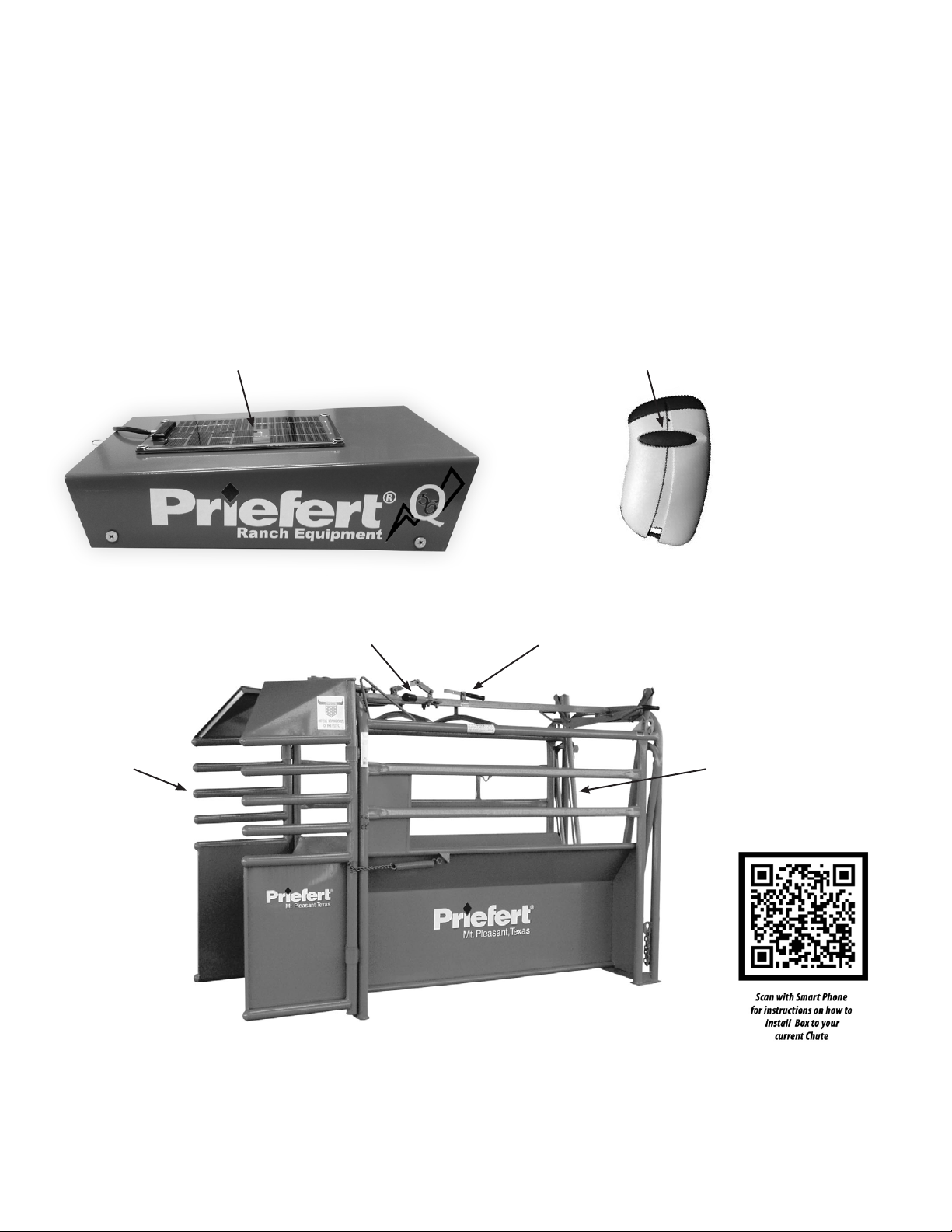
Table Of Contents
01
Weather-proof Solar Panel
Trip HandleReturn Handles
Front Gate Rear Gate
Single-Button Control
Q36 Remote Control
TRANSQ36
RC98M Part Identication
Product Identication . . . . . . . . . . . . . . . . . . . . . . . . . . . . . . . . . . . . . . . . . . . . . . . . 01
Features . . . . . . . . . . . . . . . . . . . . . . . . . . . . . . . . . . . . . . . . . . . . . . . . . . . . . . 02
Parts List . . . . . . . . . . . . . . . . . . . . . . . . . . . . . . . . . . . . . . . . . . . . . . . . . . . . . . 02
Tools Needed . . . . . . . . . . . . . . . . . . . . . . . . . . . . . . . . . . . . . . . . . . . . . . . . . . . . 02
Q36-98 Installation. . . . . . . . . . . . . . . . . . . . . . . . . . . . . . . . . . . . . . . . . . . . . . . . . 03
Step 1 - Install Release Bracket . . . . . . . . . . . . . . . . . . . . . . . . . . . . . . . . . . . . . . . . . . . 03
Step 2 - Install Spring/Spring Attachment . . . . . . . . . . . . . . . . . . . . . . . . . . . . . . . . . . . . . 03
Step 3 - Install Return Handle Brackets . . . . . . . . . . . . . . . . . . . . . . . . . . . . . . . . . . . . . . . 03
Step 4 - Install Control Box . . . . . . . . . . . . . . . . . . . . . . . . . . . . . . . . . . . . . . . . . . . . . 04
Step 5 - Installation Complete . . . . . . . . . . . . . . . . . . . . . . . . . . . . . . . . . . . . . . . . . . . 04
Step 6 - Programming Additional Remotes . . . . . . . . . . . . . . . . . . . . . . . . . . . . . . . . . . . . . 05
NOTE:
Remote is
packed inside
Q36-98 Solar Box
for shipping.
If you have questions or comments, please call:
Customer Service
1-800-527-8616
903-572-1741
Web-site address:
www.priefert.com or sales.priefert.com
For further assistance write to:
Priefert Manufacturing
Attention: Customer Service
2630 South Jeerson
P.O. Box 1540
Mount Pleasant, Texas 75456-1540
Q36-98 Solar Box
Q36

02
Parts List
Features
Tape
Measure
Tools Needed
• Fits Any Priefert RC98M!
• Requires no electrical cords or air lines, just the sun!
• Battery backup allows operation NIGHT or DAY!
• The Solar Panel is weather proof, highly ecient and virtually indestructible.
• Utilizes the latest patented high frequency pulse technology.
• Equipped with a battery backup that will allow it to operate in the event that there is no
sunlight to recharge the unit.
• A single button remote control automatically opens the chute’s front release gate.
Q36-98 Control Box with
Cover (1ea)
1 - Q36 Enclosure
1 - Q36 Box Lid
Remote
(1ea)
TRANSQ36
Top Release Bracket (1ea)
1 - S1007.19008.38-P
1 - S1001.00008.5-P
2 - NB12.75
2 - FB062.75ZPG2
2 - FN06NYLN
2 - S1601.69004.75-P
Bottom Release Bracket (1ea)
1 - S1007.19008.94-P
1 - FM05EB
1 - FN05NYLN
1 - FN0632
1 - SP110
Return Handle Brackets (2ea)
2 - S1001.63013.25P
2 - Q36HB
4 - FN06NYLN
2 - FB061.25ZPG2
Spring Bracket
(1ea)
1 - Q36SB
1 - FN06NYLN
I · FB061.25ZPG2
Box Bracket (2ea)
2 - RCF040.7503.25-P
4 - FN06NYLN
4 - FB062.50ZPG2
Handle Bolts & Nuts
(1pkg)
4 - FN10NYLN
4 - FB102.00ZPG5
Release Bracket Bolts & Nuts
(1pkg)
4 - FN06NYLN
4 · FB061.25ZPG2
//"Box-end wrench
//"Box-end wrench
Phillips
Screwdriver
//"Socket
//"Socket
Ratchet
Breaker Bar
Post extension
Release Bracket Spacer
(2ea)
2 - S1601.69004.75-P
Q36-98 Installation
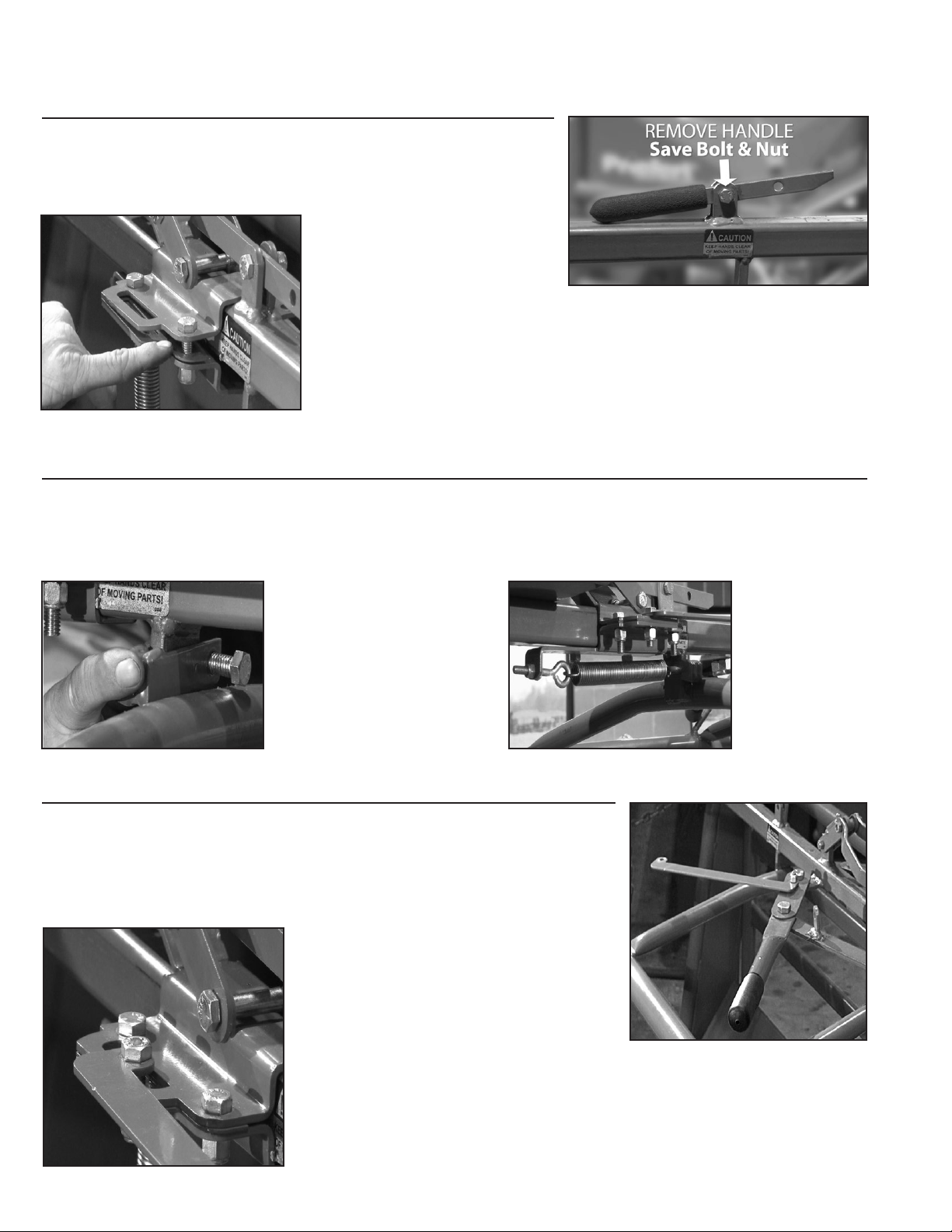
Step 1 - Install Release Bracket
Start by pushing trip handle to release front gate.
Using the /" wrench, remove trip handle (See Fig 1). Save removed
bolt & nut. Replace with Top Release Bracket, making sure top link
is tilted back. Afx through rear-most hole with saved bolt nut.
Using the /" socket and /"
box-end wrench, attach Top
Release Bracket and Bottom
Release Bracket together with
the Release Bracket Bolts and Nuts. Be Sure to include the Spacers
between the Top and Bottom Brackets (See Fig 2). Tighten all
connections securely.
Step 2 - Install Spring/Spring Attachment
Locate and install the Spring Release Bracket, just below and forward of, the Release Brackets previously
installed (See Fig 3). Note that the spring attachment link faces toward the rear of the chute. Afx with
Bolt & Nut and tighten securely. Attach spring from Bottom Release Bracket (See Fig 4).
Check Bracket/Spring for free operation.
Step 3 - Install Return Handle Brackets
Using the /" socket & Breaker Bar, remove the bolts holding the manual
gate-closing handles and discard the bolts & nuts used to attach them.
Attach the Return Handle Brackets over the gate-closing handles. The oblong
plate will locate on top of the gate-closing handle, and, ears of bracket
arms will face inward (See Fig 5). Use the provided 2" Handle Bolts & Nuts
and snug enough to allow movement.
NOTE: DO NOT OVER-TIGHTEN as
this will prevent the forward/backward
movement of the handles.
Attach other end of Return Handle to
the slot in the Release Bracket installed
earlier (See Fig 6). Using the /"
socket & Breaker Bar, SNUG bolt & nut enough to allow movement, but
DO NOT OVER-TIGHTEN.
Fig 2 - Spacers
Fig 3 - Spring Release Bracket
Fig 6 - Attach Return Handle to Release Bracket
Fig 4 - Attach Spring
Fig 5 - Gate-Closing Handles
03
Fig 1 - Remove Trip Handle
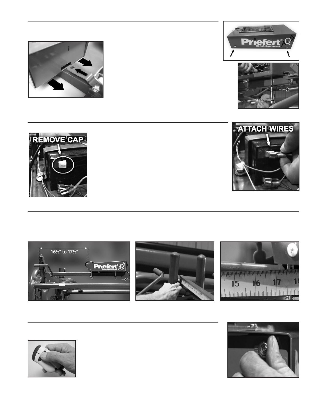
Step 4 - Install Control Box
Find and remove 4 screws from the Cover of the
Q36-98
Control Box (See Fig 7).
Place Control Box on top rail of chute just behind Release Bracket.
Slide Control Box forward so that the tongue
of the Release Bracket slides into slot and
latches inside the Control Box
(See Fig 8).
Lift Cover off Control Box and lay back onto
chute top rail. Attach Control Box to top rail with
Box Brackets, bolts & nuts (See Fig 9).
Step 4a - Connect Power Supply
IMPORTANT: To maintain the charge of the storage battery during shipment,
a protective plastic cap covers the positive lead
(See Fig 10).
Remove this protective cap and attach the duplexed
wires to the positive lead on the battery (See Fig 11).
NOTE: Q36-98 Control Box will not operate if these wires
are not connected to the storage battery.
Step 4b - Measure Location
Use Tape Measure to locate the Control Box approximately 16½" to 17½" from back of chute to back of
Control Box (See Fig 12a, Fig 12b, Fig 12c). Tighten all 4 bolts and nuts securely.
Replace Cover, replace and tighten screws.
Step 5 - Installation Complete
Close Front Gate. Turn on Power Switch (See Fig 13). Front Gate will release,
which indicates the
Q36-98
is active and functioning
Chute Is now ready to operate with the Q36-98 Solar Powered
Control Box. Operation is easily handled with one button on the
Remote (See Fig 14). Remote is programmed from the factory,
but if an additional remote is desired, it will need
to be programmed to your Control Box (See Step 6).
04
Fig 9 - Attach Control Box
Fig 12a - Location of Control Box Fig 12b - Measure from Back of Chute Fig 12c - to Back of Control Box
Fig 13 - Power Switch
Fig 14 - One-Button Remote
Fig 8 - Latch Tongue
into Control Box
Fig 10 - Remove Protective Cap Fig 11 - Attach Duplexed Wires
Fig 7 - Remove Screws

Step 6 - Programming Additional Remotes
The Q36-98 Comes with one Remote control pre-programmed from the factory.
However, additional Remotes may be purchased for convenience. Any additional
remotes will need to be programed to the Control Box. The following steps will
guide you through the programming process.
Find and remove 4 screws from the Cover of the
Q36-98
Control Box (See Fig 15). Lift Cover off
Control Box and lay back onto chute top rail.
1. Locate the circuit board box and remove the two
screws holding the cover (See Fig 16). Turn power
on, Green LED power light will illuminate. Press
and hold the function button until Red LED light
illuminates (See Fig 17).
2. While red LED light is on, press the button on the
Remote (See Fig 18). The LED light will blink and
Chute release will trip to indicate programming is
active. When red LED light goes off, programming
is complete. Replace cover on circuit board box,
and cover on Control Box.
Repeat this process for any additional Remote programming.
Fig 15 - Remove Screws
Fig 16 - Circuit Board Box
Fig 18 - Program Remote
Fig 17 - Circuit Board Box Components
RED
LED
LIGHT
GREEN
POWER
LIGHT
FUNCTION
BUTTON
Table of contents


