SMA Solar Technology AG GRID-CONNECT-BOX 12 User manual
GRID-BOX-12-3-20-BE-en-11 | Version 1.1 ENGLISH
Operating Manual
GRID-CONNECT-BOX 12

Legal Provisions SMA Solar Technology AG
2 GRID-BOX-12-3-20-BE-en-11 Operating Manual
Legal Provisions
The information contained in this document is the property of SMA Solar Technology AG. Publishing its content, either
partially or in full, requires the written permission of SMA Solar Technology AG. Any internal company copying of the
document for the purposes of evaluating the product or its correct implementation is allowed and does not require
permission.
SMA Warranty
You can download the current warranty conditions from the Internet at www.SMA-Solar.com.
Trademarks
All trademarks are recognized, even if not explicitly identified as such. A lack of identification does not mean that a
product or symbol is not trademarked.
The BLUETOOTH® word mark and logos are registered trademarks owned by Bluetooth SIG, Inc. and any use of these
marks by SMA Solar Technology AG is under license.
Modbus® is a registered trademark of Schneider Electric and is licensed by the Modbus Organization, Inc.
QR Code is a registered trademark of DENSO WAVE INCORPORATED.
Phillips® and Pozidriv® are registered trademarks of Phillips Screw Company.
Torx® is a registered trademark of Acument Global Technologies, Inc.
SMA Solar Technology AG
Sonnenallee 1
34266 Niestetal
Germany
Tel. +49 561 9522-0
Fax +49 561 9522-100
www.SMA.de
E-mail: [email protected]
© 2004 to 2016 SMA Solar Technology AG. All rights reserved.

SMA Solar Technology AG Table of Contents
Operating Manual GRID-BOX-12-3-20-BE-en-11 3
Table of Contents
1 Information on this Document. . . . . . . . . . . . . . . . . . . . . . . . . . . . . . . . . . . . . . . . . . . . . . . . . . . . . 5
1.1 Validity . . . . . . . . . . . . . . . . . . . . . . . . . . . . . . . . . . . . . . . . . . . . . . . . . . . . . . . . . . . . . . . . . . . . . . . . . . . . . . 5
1.2 Target Group . . . . . . . . . . . . . . . . . . . . . . . . . . . . . . . . . . . . . . . . . . . . . . . . . . . . . . . . . . . . . . . . . . . . . . . . . 5
1.3 Additional Information . . . . . . . . . . . . . . . . . . . . . . . . . . . . . . . . . . . . . . . . . . . . . . . . . . . . . . . . . . . . . . . . . . 5
1.4 Symbols . . . . . . . . . . . . . . . . . . . . . . . . . . . . . . . . . . . . . . . . . . . . . . . . . . . . . . . . . . . . . . . . . . . . . . . . . . . . . 5
1.5 Typographies . . . . . . . . . . . . . . . . . . . . . . . . . . . . . . . . . . . . . . . . . . . . . . . . . . . . . . . . . . . . . . . . . . . . . . . . . 6
1.6 Nomenclature. . . . . . . . . . . . . . . . . . . . . . . . . . . . . . . . . . . . . . . . . . . . . . . . . . . . . . . . . . . . . . . . . . . . . . . . . 6
2 Safety . . . . . . . . . . . . . . . . . . . . . . . . . . . . . . . . . . . . . . . . . . . . . . . . . . . . . . . . . . . . . . . . . . . . . . . . 7
2.1 Intended Use . . . . . . . . . . . . . . . . . . . . . . . . . . . . . . . . . . . . . . . . . . . . . . . . . . . . . . . . . . . . . . . . . . . . . . . . . 7
2.2 Safety Information . . . . . . . . . . . . . . . . . . . . . . . . . . . . . . . . . . . . . . . . . . . . . . . . . . . . . . . . . . . . . . . . . . . . . 9
3 Scope of Delivery. . . . . . . . . . . . . . . . . . . . . . . . . . . . . . . . . . . . . . . . . . . . . . . . . . . . . . . . . . . . . . 10
4 Product Description . . . . . . . . . . . . . . . . . . . . . . . . . . . . . . . . . . . . . . . . . . . . . . . . . . . . . . . . . . . . 11
4.1 Grid-Connect-Box . . . . . . . . . . . . . . . . . . . . . . . . . . . . . . . . . . . . . . . . . . . . . . . . . . . . . . . . . . . . . . . . . . . . . 11
4.2 Type Label . . . . . . . . . . . . . . . . . . . . . . . . . . . . . . . . . . . . . . . . . . . . . . . . . . . . . . . . . . . . . . . . . . . . . . . . . . 13
5 Installation . . . . . . . . . . . . . . . . . . . . . . . . . . . . . . . . . . . . . . . . . . . . . . . . . . . . . . . . . . . . . . . . . . . 14
5.1 Storing the Grid-Connect-Box. . . . . . . . . . . . . . . . . . . . . . . . . . . . . . . . . . . . . . . . . . . . . . . . . . . . . . . . . . . . 14
5.2 Requirements for Mounting. . . . . . . . . . . . . . . . . . . . . . . . . . . . . . . . . . . . . . . . . . . . . . . . . . . . . . . . . . . . . . 14
5.3 Preparing the Mounting Location . . . . . . . . . . . . . . . . . . . . . . . . . . . . . . . . . . . . . . . . . . . . . . . . . . . . . . . . . 15
5.4 Transport. . . . . . . . . . . . . . . . . . . . . . . . . . . . . . . . . . . . . . . . . . . . . . . . . . . . . . . . . . . . . . . . . . . . . . . . . . . . 15
5.4.1 Transport Options . . . . . . . . . . . . . . . . . . . . . . . . . . . . . . . . . . . . . . . . . . . . . . . . . . . . . . . . . . . . . . . . . . . . . . .15
5.4.2 Transporting and Mounting the Grid-Connect-Box . . . . . . . . . . . . . . . . . . . . . . . . . . . . . . . . . . . . . . . . . . . . . .16
6 Electrical Connection . . . . . . . . . . . . . . . . . . . . . . . . . . . . . . . . . . . . . . . . . . . . . . . . . . . . . . . . . . . 17
6.1 Overview of the Connection Area . . . . . . . . . . . . . . . . . . . . . . . . . . . . . . . . . . . . . . . . . . . . . . . . . . . . . . . . 17
6.1.1 Components and Terminals . . . . . . . . . . . . . . . . . . . . . . . . . . . . . . . . . . . . . . . . . . . . . . . . . . . . . . . . . . . . . . . .17
6.1.2 Enclosure Openings in the Floor . . . . . . . . . . . . . . . . . . . . . . . . . . . . . . . . . . . . . . . . . . . . . . . . . . . . . . . . . . . .18
6.2 Deactivating All-Pole Disconnection . . . . . . . . . . . . . . . . . . . . . . . . . . . . . . . . . . . . . . . . . . . . . . . . . . . . . . . 18
6.3 Connecting the Multicluster-Box . . . . . . . . . . . . . . . . . . . . . . . . . . . . . . . . . . . . . . . . . . . . . . . . . . . . . . . . . . 18
6.4 Connecting the Utility Grid . . . . . . . . . . . . . . . . . . . . . . . . . . . . . . . . . . . . . . . . . . . . . . . . . . . . . . . . . . . . . . 19
6.5 Connecting the Control Cables . . . . . . . . . . . . . . . . . . . . . . . . . . . . . . . . . . . . . . . . . . . . . . . . . . . . . . . . . . 19
6.6 Mounting the Kick Plates . . . . . . . . . . . . . . . . . . . . . . . . . . . . . . . . . . . . . . . . . . . . . . . . . . . . . . . . . . . . . . . 20
7 Preparing the Multicluster System for Commissioning . . . . . . . . . . . . . . . . . . . . . . . . . . . . . . . . 21
8 Disconnecting the Grid-Connect-Box and Multicluster System from Voltage Sources. . . . . . . 22
9 Periodic Actions . . . . . . . . . . . . . . . . . . . . . . . . . . . . . . . . . . . . . . . . . . . . . . . . . . . . . . . . . . . . . . . 23
9.1 Removing the Protective Cover . . . . . . . . . . . . . . . . . . . . . . . . . . . . . . . . . . . . . . . . . . . . . . . . . . . . . . . . . . . 23
9.2 Mounting the Protective Cover . . . . . . . . . . . . . . . . . . . . . . . . . . . . . . . . . . . . . . . . . . . . . . . . . . . . . . . . . . . 24
9.3 Inserting the Cables . . . . . . . . . . . . . . . . . . . . . . . . . . . . . . . . . . . . . . . . . . . . . . . . . . . . . . . . . . . . . . . . . . . 25
9.4 Connection to Spring-Cage Terminals . . . . . . . . . . . . . . . . . . . . . . . . . . . . . . . . . . . . . . . . . . . . . . . . . . . . . 26
9.4.1 Connecting Power Cables to Spring-Cage Terminals . . . . . . . . . . . . . . . . . . . . . . . . . . . . . . . . . . . . . . . . . . . .26
9.4.2 Connecting Control Cables to Spring-Cage Terminals . . . . . . . . . . . . . . . . . . . . . . . . . . . . . . . . . . . . . . . . . . .27

Table of Contents SMA Solar Technology AG
4 GRID-BOX-12-3-20-BE-en-11 Operating Manual
10 Maintenance . . . . . . . . . . . . . . . . . . . . . . . . . . . . . . . . . . . . . . . . . . . . . . . . . . . . . . . . . . . . . . . . . .28
10.1 Testing the Residual-Current Device . . . . . . . . . . . . . . . . . . . . . . . . . . . . . . . . . . . . . . . . . . . . . . . . . . . . . . . 28
10.2 Testing the Surge Arrester . . . . . . . . . . . . . . . . . . . . . . . . . . . . . . . . . . . . . . . . . . . . . . . . . . . . . . . . . . . . . . 29
10.3 Maintenance Work Every 12 Months . . . . . . . . . . . . . . . . . . . . . . . . . . . . . . . . . . . . . . . . . . . . . . . . . . . . . 29
11 Decommissioning . . . . . . . . . . . . . . . . . . . . . . . . . . . . . . . . . . . . . . . . . . . . . . . . . . . . . . . . . . . . . .31
11.1 Disassembling the Grid-Connect-Box. . . . . . . . . . . . . . . . . . . . . . . . . . . . . . . . . . . . . . . . . . . . . . . . . . . . . . 31
11.2 Disposing of the Grid-Connect-Box . . . . . . . . . . . . . . . . . . . . . . . . . . . . . . . . . . . . . . . . . . . . . . . . . . . . . . . 31
12 Technical Data. . . . . . . . . . . . . . . . . . . . . . . . . . . . . . . . . . . . . . . . . . . . . . . . . . . . . . . . . . . . . . . . .32
13 Contact. . . . . . . . . . . . . . . . . . . . . . . . . . . . . . . . . . . . . . . . . . . . . . . . . . . . . . . . . . . . . . . . . . . . . . .35
SMA Solar Technology AG 1 Information on this Document
Operating Manual GRID-BOX-12-3-20-BE-en-11 5
1 Information on this Document
1.1 Validity
This document is valid for the device type "GRID-CONNECT-BOX 12.3-20" (Grid-Connect-Box 12).
1.2 Target Group
The activities described in this document must be performed by qualified persons only. Qualified persons must have the
following skills:
• Training in how to deal with the dangers and risks associated with installing and operating electrical devices and
batteries
• Training in the installation and commissioning of electrical devices
• Knowledge of and adherence to the local standards and directives
• Knowledge of and compliance with this document and all safety information
1.3 Additional Information
Links to additional information can be found at www.SMA-Solar.com:
1.4 Symbols
Document title Document type
MULTICLUSTER-BOX 12 Installation – circuitry overview
MULTICLUSTER-BOX 12 Operating manual
Symbol Explanation
'$1*(5
Indicates a hazardous situation that, if not avoided, will result in death or serious injury
:$51,1*
Indicates a hazardous situation that, if not avoided, can result in death or serious injury
&$87,21
Indicates a hazardous situation that, if not avoided, can result in minor or moderate injury
/05*$&
Indicates a situation that, if not avoided, can result in property damage
Information that is important for a specific topic or goal, but is not safety-relevant
Indicates a requirement for meeting a specific goal
Desired result
✖ A problem that might occur

1 Information on this Document SMA Solar Technology AG
6 GRID-BOX-12-3-20-BE-en-11 Operating Manual
1.5 Typographies
1.6 Nomenclature
Typography Application Example
bold • Display messages
• Parameter
•Terminals
•Slots
• Elements to be selected or
entered
• Connect the neutral conductor to the
spring-cage terminal N at terminal X301:6.
• Connect the line conductors to the
spring-cage terminals L1, L2 and L3 at the
terminals X301:8-10.
>• Connects several elements to be
selected
–
[Button/Key] • Button on the device to be
selected or pressed
•Press the [TEST] button.
Complete designation Designation in this document
Grid-Connect-Box12 Grid-Connect-Box
Multicluster-Box 12 Multicluster-Box
SMA Solar Technology AG 2 Safety
Operating Manual GRID-BOX-12-3-20-BE-en-11 7
2 Safety
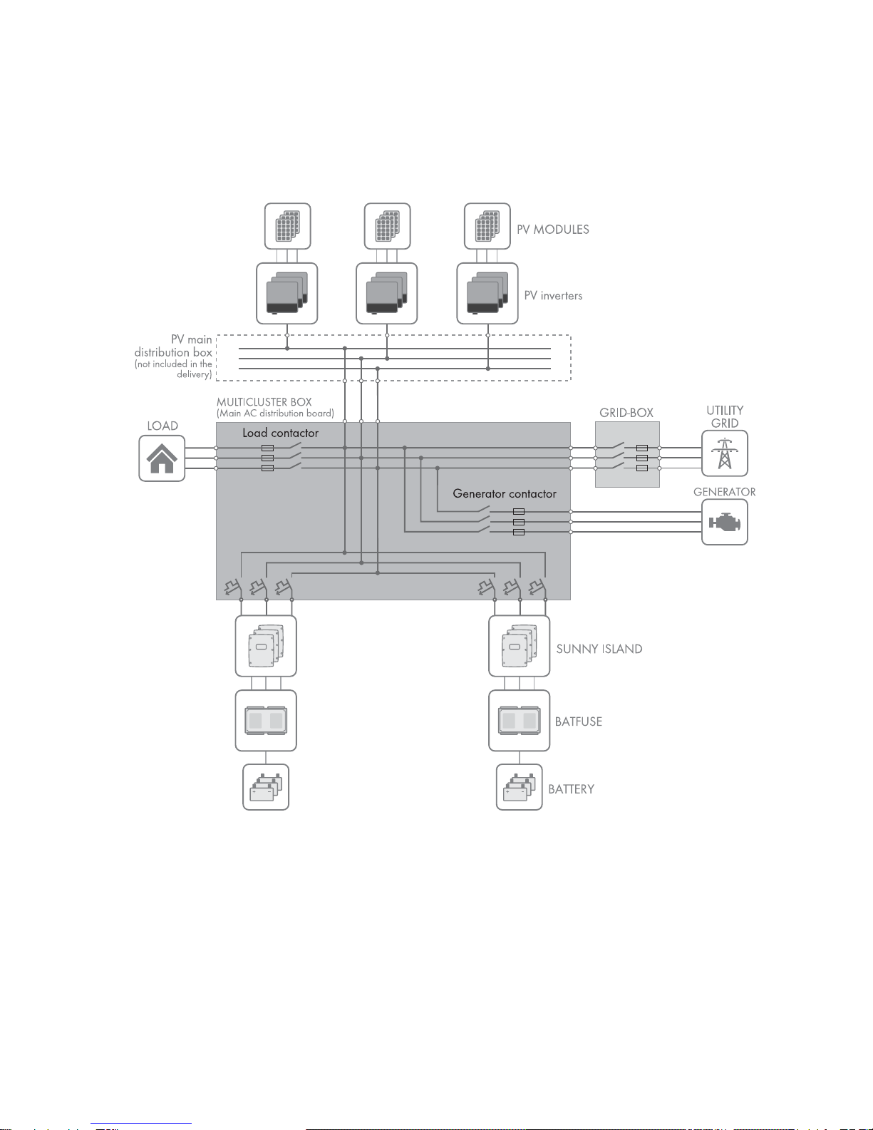
2.1 Intended Use
The Grid-Connect-Box is an automatic transfer switch which enables the safe operation of the utility grid and an electricity
generator as energy sources of an SMA multicluster system.
Figure1: Circuitry principle of a multicluster system with the Grid-Connect-Box
The technical connection requirements of the grid operator and the local standards and directives specify whether the
multicluster system, in the event of grid failure, disconnects from the utility grid at all poles or only the line conductors.
The Grid-Connect-Box is always supplied with an all-pole disconnection function. If all-pole disconnection is not permitted,
the Grid-Connect-Box all-pole disconnection function must be deactivated(see Section6.2, page18).
If the Grid-Connect-Box is used with all-pole disconnection, the utility grid must be either a TN-S, TN-C-S or TT system.
If the Grid-Connect-Box is used without all-pole disconnection, the utility grid must be a TN-C-S system (for grounding in
the multicluster system, see the Multicluster-Box operating manual).
Do not exceed the maximum AC connection power of the Grid-Connect-Box. Cables with copper conductors must be
used for the installation.

2 Safety SMA Solar Technology AG
8 GRID-BOX-12-3-20-BE-en-11 Operating Manual
In terms of interference immunity, the product is suitable for EMC environment A, and in terms of EMC emissions, it is
suitable for EMC environment B* .
The Grid-Connect-Box may only be commissioned in conjunction with the Multicluster-Box.
The Grid-Connect-Box is designed for use at altitudes of up to 3000 m above Mean Sea Level. If you would like to use
the Grid-Connect-Box at altitudes above 3000 m, contact Service (see Section13, page35).
The Grid-Connect-Box is suitable for indoor use. The product may only be operated at temperatures between −25°C and
+60°C.
All work on the product must only be performed using appropriate tools and in compliance with the ESD protection
regulations.
Suitable personal protective equipment must be worn by all persons working on or with the product.
Use this product only in accordance with the information provided in the enclosed documentation and with the locally
applicable standards and directives. Any other application may cause personal injury or property damage. Alterations
to the product, e.g. modifications or conversions, are only permitted with the express written permission of
SMA Solar Technology AG. Unauthorized alterations will void guarantee and warranty claims and will usually void the
operation license. SMA Solar Technology AG shall not be held liable for any damage caused by such alterations.
Any use of the product other than that described in the Intended Use section does not qualify as the intended use.
The enclosed documentation is an integral part of this product. Keep the documentation in a convenient place for future
reference and observe all instructions contained therein.
The type label must remain permanently attached to the product.
* In accordance with IEC 61439-1:2011

SMA Solar Technology AG 2 Safety
Operating Manual GRID-BOX-12-3-20-BE-en-11 9
2.2 Safety Information
This Section contains safety information that must be observed at all times during work on or with the product.
To prevent personal injury and property damage and to ensure long-term operation of the product, read this Section
carefully and observe all safety information at all times.
'$1*(5
Danger to life due to electric shock
High voltages are present in the Grid-Connect-Box and the multicluster system. Touching live components results in
death or serious injury due to electric shock.
• Disconnect the Grid-Connect-Box and multicluster system from all voltage sources before carrying out any work
on the Grid-Connect-Box (see Section8, page22).
• Only operate the Grid-Connect-Box with its protective cover in place.
• Work on the Grid-Connect-Box may only be performed by qualified persons.
• Do not touch any live components in the Grid-Connect-Box or any other components in the multicluster system.
&$87,21
Risk of injury if the Grid-Connect-Box tips over
The Grid-Connect-Box is heavy and may tip over if not properly fastened to the support surface. This can result in injuries
due to crushing.
• Upon installation, attach the Grid-Connect-Box to the support surface.
&$87,21
Risk of burns due to hot components
Components and terminals inside the Grid-Connect-Box can become hot during operation. Touching hot components
can cause burns.
• Only operate the Grid-Connect-Box with its protective cover in place.
• Prior to removing the protective cover, let the Grid-Connect-Box cool down.
Effects of an emergency disconnection
Emergency disconnection of the Sunny Island triggers the uncontrolled shutdown of the system, resulting in any
unsaved data being lost.
• Only use the emergency disconnection to avoid danger or consequential damage.
• In the event of an emergency disconnection, always check whether any fuse elements in the Grid-Connect-Box,
such as circuit breakers, have tripped.
If any fuse elements have tripped, reactivate these fuse elements.
3 Scope of Delivery SMA Solar Technology AG
10 GRID-BOX-12-3-20-BE-en-11 Operating Manual
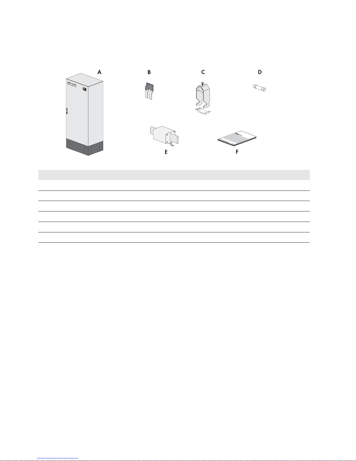
3 Scope of Delivery
Check the scope of delivery for completeness and any externally visible damage. Contact your distributor if the scope of
delivery is incomplete or damaged.
Figure2: Components included in the scope of delivery
Position Quantity Designation
A 1 Grid-Connect-Box
B 1 Two-pole N bridge
C 10 Strain relief with counter-sleeve (22 mm to 28 mm)
D 2 Fuse link (1 A, tripping characteristic gG)
E 2 LV/HRC fuse link (200 A, tripping characteristic: gG)
F 1 Operating manual
SMA Solar Technology AG 4 Product Description
Operating Manual GRID-BOX-12-3-20-BE-en-11 11
4 Product Description
4.1 Grid-Connect-Box
The Grid-Connect-Box is an automatic transfer switch which enables the safe operation of the utility grid and an electricity
generator as energy sources of an SMA Multicluster System.
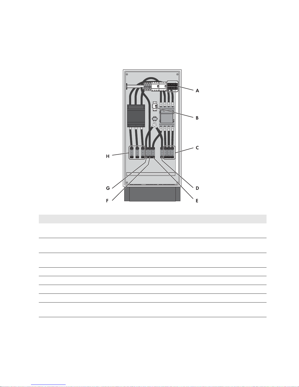
Figure3: Grid-Connect-Box with cabinet door open
Position Designation Explanation
A Protective cover Prevents inadvertent contact with live components during
operation and thus protects from electric shocks. The protective
cover must always be in position when the Grid-Connect-Box is in
operation.
B Fuse holder 1 A Receptacle for cylindrical thermal fuses (1 A, tripping
characteristic gG). The thermal fuses protect the connected
conductors from excessive heat build-up due to overload or short
circuits.
C Residual-current device Protects against electric shock and is always used in addition to
existing protective measures such as insulation or protective
grounding. As soon as a dangerous touch voltage occurs, the
residual-current device disconnects all poles of the loads.
This is achieved by means of a summation current transformer in
the residual-current device which detects the electric currents in
the conductors L1, L2, L3 and N. In the normal operating state,
the sum of these currents equals zero. Under fault conditions a
differential current is formed which trips the residual-current
device.

4 Product Description SMA Solar Technology AG
12 GRID-BOX-12-3-20-BE-en-11 Operating Manual
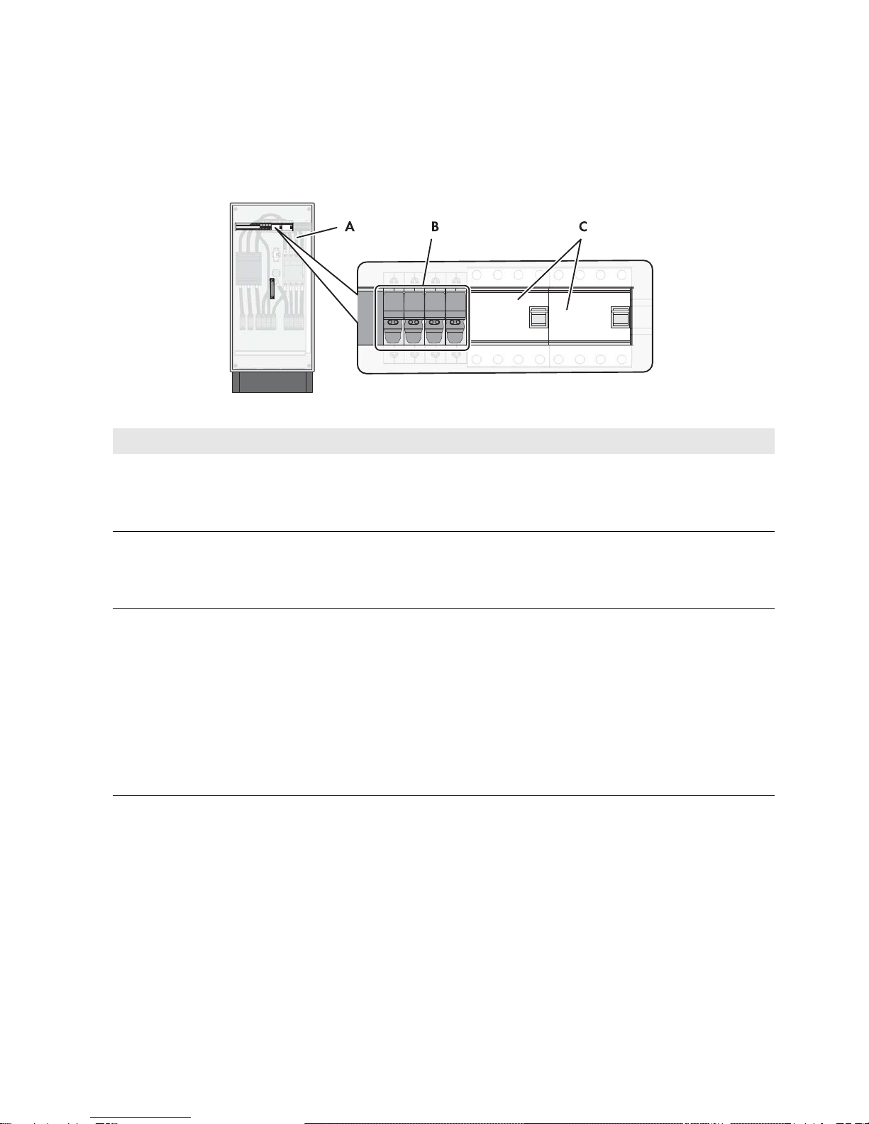
Residual-current device
Figure4: Overview of the residual-current device
Position Designation Explanation
A Test button The functionality of the residual-current device must be tested
regularly (see Section10.1, page28).
B Switch lever Top position: ON - residual-current device is switched on.
Bottom position: OFF - residual-current device has tripped or
is switched off.

SMA Solar Technology AG 4 Product Description
Operating Manual GRID-BOX-12-3-20-BE-en-11 13
4.2 Type Label
The type label clearly identifies the product. The type label is located on the right-hand side of the enclosure.
You will find the following information on the type label:
• Address of SMA Solar Technology AG
• Device type (Type)
• Serial number (Serial No.)
• Article number (Art No.)
• Device-specific characteristics
You will require the information on the type label to use the product safely and when seeking customer support from
Service.
Symbols on the type label
Symbol Explanation
Danger to life due to high voltages
The product operates at high voltages. All work on the product must be carried out by qualified
persons only.
Risk of burns due to hot surfaces
The product can become hot during operation. Avoid contact during operation. Allow the product
to cool down sufficiently before carrying out any work. Wear personal protective equipment such as
safety gloves.
Observe the documentation
Observe all documentation supplied with the product.
WEEE designation
Do not dispose of the product together with the household waste but in accordance with the locally
applicable disposal regulations for electronic waste.
CE marking
The product complies with the requirements of the applicable EU directives.
Degree of protection
The product is protected against interior dust deposits and water jets from all angles.
5 Installation SMA Solar Technology AG
14 GRID-BOX-12-3-20-BE-en-11 Operating Manual
5 Installation
5.1 Storing the Grid-Connect-Box
• Store the Grid-Connect-Box in a dry place at an ambient temperature of between − 25°C and +60°C.
5.2 Requirements for Mounting
Mounting Location
A firm, even support surface, e.g., a concrete foundation, must be available for mounting.
The mounting location must be suitable for the weight and dimensions of the Grid-Connect-Box (see Section12
"Technical Data", page32).
The mounting location must be clear and safely accessible at all times without any need for auxiliary equipment.
The mounting location must not hinder access to disconnection devices.
All local requirements concerning minimum passage widths and escape routes must be observed.
Climatic conditions must be met (see Section12 "Technical Data", page32).
The mounting location must be below 3000 m above MSL. If you would like to use the Grid-Connect-Box at altitudes
above 3000 m, contact Service (see Section13, page35).
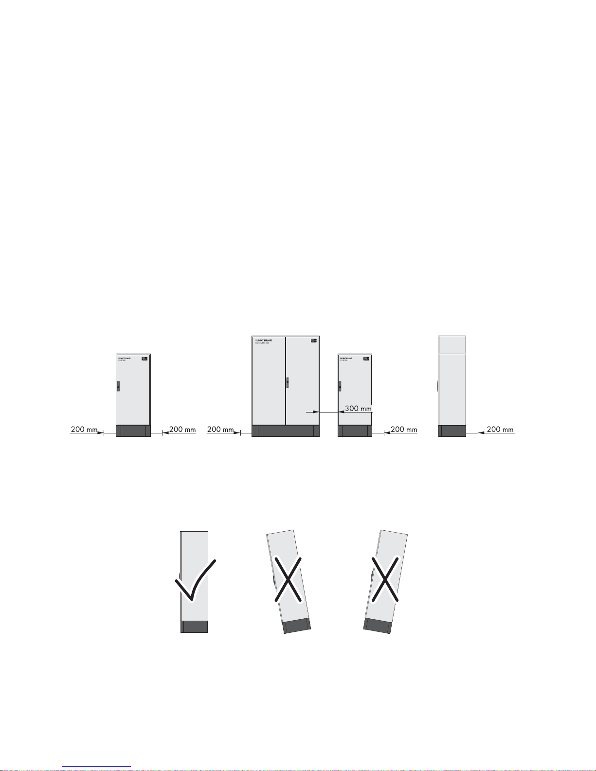
Minimum clearances
Figure5: Minimum clearances
There must be sufficient space at the mounting location to ensure compliance with the minimum clearances.
There must be a distance of at least 300 mm between the Grid-Connect-Box and the Multicluster-Box. This will ensure
adequate heat dissipation.
Mounting position
Figure6: Permitted and prohibited mounting positions
The mounting location must be suitable to ensure compliance with the permitted mounting position.
SMA Solar Technology AG 5 Installation
Operating Manual GRID-BOX-12-3-20-BE-en-11 15
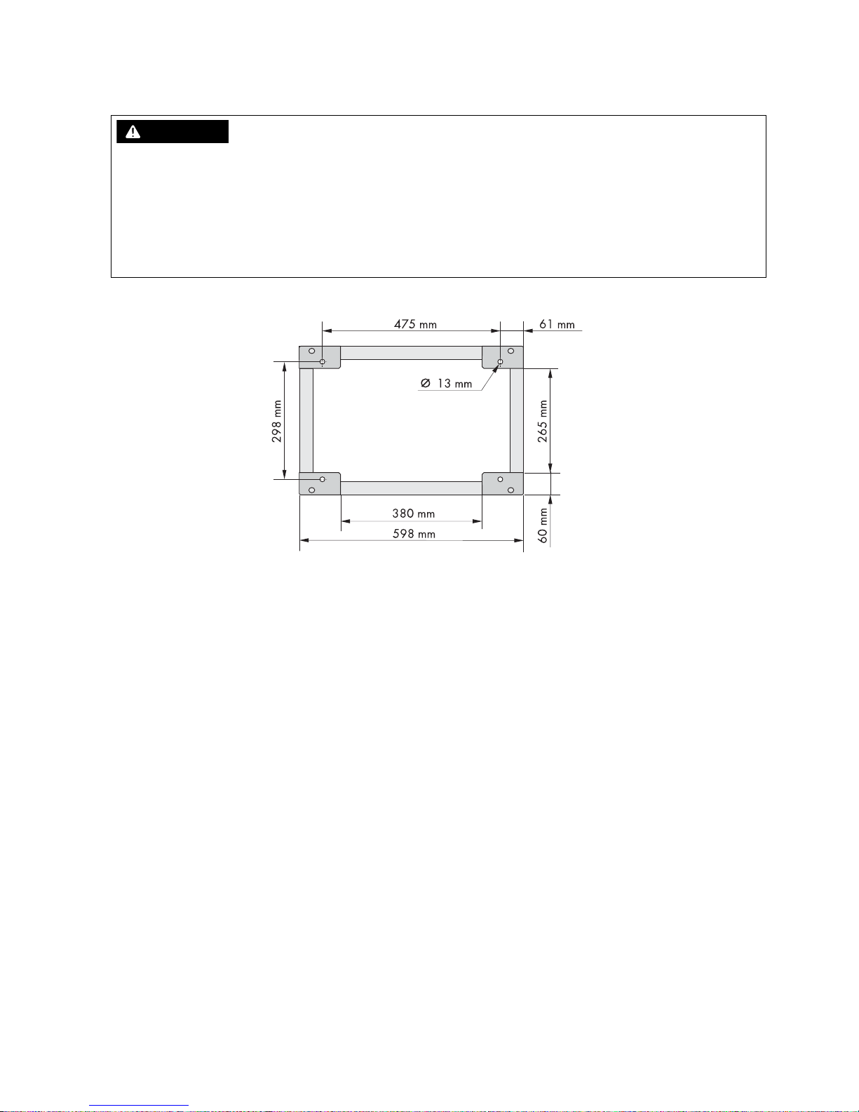
5.3 Preparing the Mounting Location
Dimensions of the drill holes for securing the Grid-Connect-Box:
Figure7: Exterior base measurements and dimensions of the drill holes
Additionally required mounting material (not included in the scope of delivery):
4 suitable screw anchors for attaching the Grid-Connect-Box
Procedure:
1. On the support surface, mark the positions of the four drill holes for attaching the base.
2. Drill holes at the marked positions.
3. Insert the screw anchors.
5.4 Transport
5.4.1 Transport Options
The Grid-Connect-Box is delivered on a Euro pallet. You can use the following means of transport to lift the
Grid-Connect-Box off the Euro pallet:
•Forklift
• Crane with suitable fork
:$51,1*
Danger to life due to fire or explosion
Despite careful construction, electronic devices can cause fires if they are not installed properly. Contact with flammable
materials allows the fire to spread. This can result in death or serious injury.
• Do not install the Grid-Connect-Box on flammable construction materials.
• Do not install the Grid-Connect-Box in areas containing flammable substances or objects.
• Do not install the Grid-Connect-Box in potentially explosive atmospheres.
5 Installation SMA Solar Technology AG
16 GRID-BOX-12-3-20-BE-en-11 Operating Manual
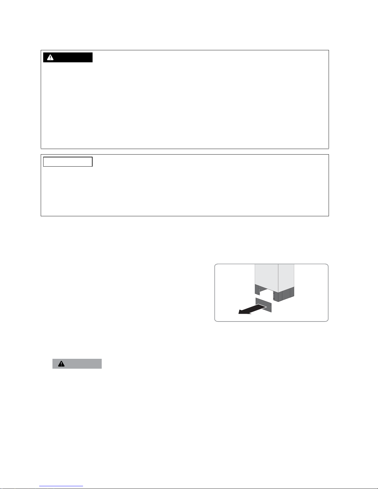
5.4.2 Transporting and Mounting the Grid-Connect-Box
Additionally required mounting material (not included in the scope of delivery):
4 suitable screws for attaching the Grid-Connect-Box to the support surface
Procedure:
1. Remove all fastening screws from the kick plates at the front and rear (TX 30).
2. Remove the kick plates.
3. Retain the kick plates and the fastening screws for later use.
4. Push the means of transport under the Grid-Connect-Box and transport the Grid-Connect-Box to the mounting
location.
:$51,1*
Danger of crushing if the raised or suspended Grid-Connect-Box tips over or falls
The Grid-Connect-Box can tip over or fall if it is lifted and transported carelessly or hastily. This can result in death or
serious injury.
• Always transport the Grid-Connect-Box as close to the ground as possible.
• Use a means of transportation which is suitable for the weight of the Grid-Connect-Box of 103 kg.
• Transport the Grid-Connect-Box in an upright position.
• Keep a safe distance from the Grid-Connect-Box at all times during transport.
• Be aware of the center of gravity of the Grid-Connect-Box. The center of gravity of the Grid-Connect-Box is located
approximately in the center of the cabinet and is marked on the enclosure with the center of gravity symbol.
/05*$&
Damage to the Grid-Connect-Box due to inappropriate transport
Setting the Grid-Connect-Box down on uneven surfaces can lead to the Grid-Connect-Box buckling and the doors no
longer closing properly. This can lead to moisture or dust penetrating the Grid-Connect-Box.
• Do not set the Grid-Connect-Box down on unpaved, uneven surfaces.
• Do not transport the Grid-Connect-Box with the kick plates mounted.
5.
&$87,21
Risk of injury if the Grid-Connect-Box tips over
The Grid-Connect-Box is heavy and may tip over if not properly fastened to the support surface. This can result in
injuries due to crushing.
• Attach the Grid-Connect-Box to the support surface using four suitable screws.
SMA Solar Technology AG 6 Electrical Connection
Operating Manual GRID-BOX-12-3-20-BE-en-11 17
6 Electrical Connection
6.1 Overview of the Connection Area
6.1.1 Components and Terminals
Figure8: Overview of the connection area
Position Designation Explanation
ATerminals X310, X311 with spring-cage
terminals
Spring-cage terminals for connecting the control cables
B Surge arrester The signal light on the surge arrester must be checked
regularly (see Section10.2, page29).
CTerminals X301:8-10 with spring-cage
terminals L1, L2 and L3
For connecting the Multicluster-Box line conductors
DTerminal X301:7 with spring-cage terminal PE For connecting the Multicluster-Box grounding conductor
E Terminal X301:6 with spring-cage terminal NFor connecting the Multicluster-Box neutral conductor
FTerminal X301:5 with spring-cage terminal NFor connecting the utility grid neutral conductor
GTerminal X301:4 with spring-cage terminal PE For connecting the utility grid grounding conductor
HTerminals X301:1-3 with spring-cage
terminals L1, L2 and L3
For connecting the utility grid line conductors
6 Electrical Connection SMA Solar Technology AG
18 GRID-BOX-12-3-20-BE-en-11 Operating Manual
6.1.2 Enclosure Openings in the Floor
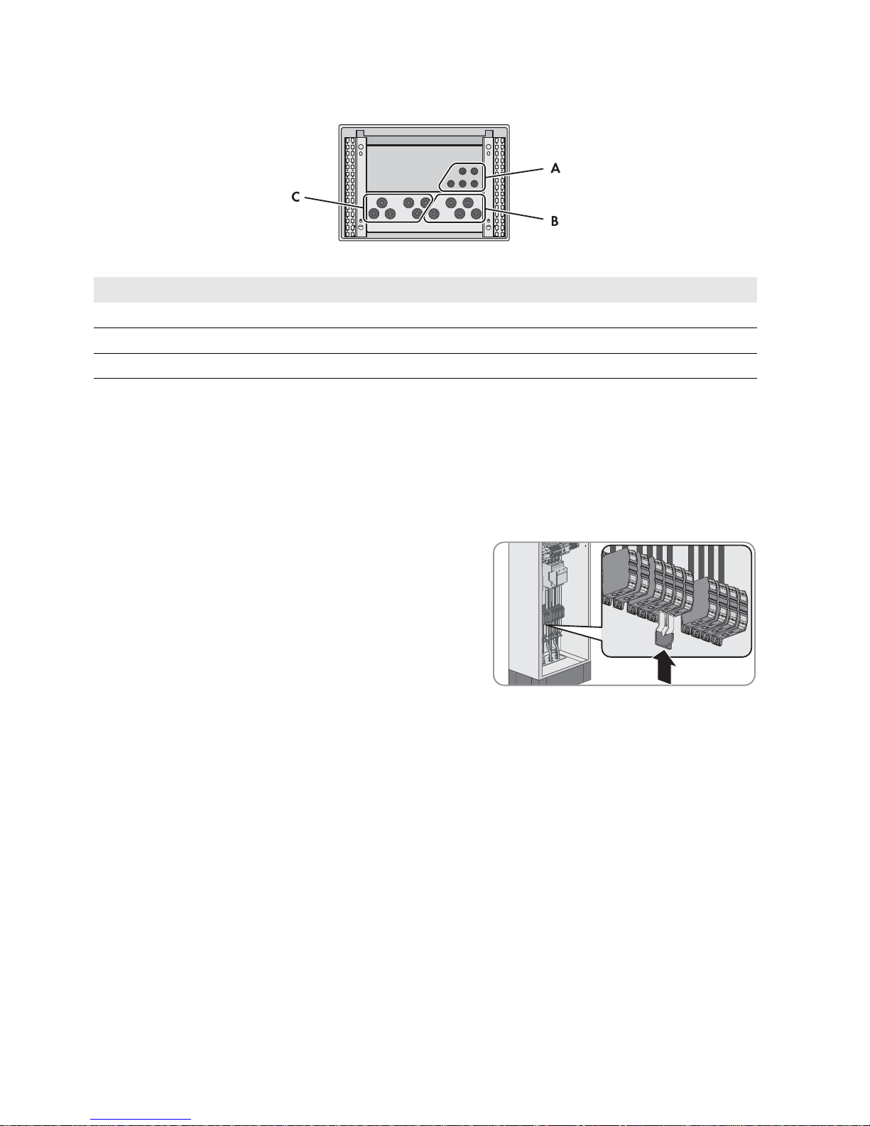
Figure9: Position of the enclosure openings
6.2 Deactivating All-Pole Disconnection
The technical connection requirements of the grid operator and the local standards and directives specify whether the
multicluster system, in the event of grid failure, disconnects from the utility grid at all poles or only the line conductors. The
Grid-Connect-Box is always supplied with an all-pole disconnection function. If all-pole disconnection is not permitted,
you must deactivate the Grid-Connect-Box all-pole disconnection function. To do this, insert the two-pole N bridge
included in the scope of delivery as follows:
Procedure:
• For use of the Grid-Connect-Box without all-pole disconnection,
connect the spring-cage terminal N on X301:5 to the spring-cage
terminal N on X301:6. To do this, plug the two-pole N bridge
included in the scope of delivery into the spring-cage terminals
from below.
6.3 Connecting the Multicluster-Box
Cable requirements:
Conductor material: copper
Conductor cross-section: 50 mm² to 150 mm²
The power cables must be ground-fault- and short-circuit protected.
The line conductors, neutral conductor and grounding conductor must have the same cross-section.
The AC conductors and DC conductors must always be routed in separate cables.
Procedure:
1. Insert the Multicluster-Box power cables into the Grid-Connect-Box (see Section9.3, page25).
2. Connect the grounding conductor to the spring-cage terminal PE at terminal X301:7 (see Section9.4.1, page26).
3. Connect the neutral conductor to the spring-cage terminal N at terminal X301:6.
4. Connect the line conductors to the spring-cage terminals L1, L2 and L3 at the terminals X301:8-10.
5. Ensure that a right-hand rotating magnetic field is present at the connection point of the Multicluster-Box.
6. Provide for strain relief of the power cables in the spring-cage terminal by attaching them to the appropriate cable
support rail. Use the strain reliefs and counter-sleeves included in the scope of delivery for this.
Position Explanation
A Enclosure openings for the control cables
B Enclosure openings for the Multicluster-Box power cables
C Enclosure openings for the utility grid power cables
SMA Solar Technology AG 6 Electrical Connection
Operating Manual GRID-BOX-12-3-20-BE-en-11 19
6.4 Connecting the Utility Grid
Cable requirements:
Conductor material: copper
The conductor cross-section must be selected according to the rated input power of the utility grid.
Conductor cross-section: 50 mm² to 150 mm²
The power cables must be ground-fault- and short-circuit protected.
The line conductors, neutral conductor and grounding conductor must have the same cross-section.
The AC conductors and DC conductors must always be routed in separate cables.
Procedure:
1. Insert the Multicluster-Box power cables into the Grid-Connect-Box (see Section9.3, page25).
2. Connect the grounding conductor to the spring-cage terminal PE at terminal X301:4 (see Section9.4.1, page26).
3. Connect the neutral conductor to the spring-cage terminal N at terminal X301:5.
4. Connect the line conductors to the spring-cage terminals L1, L2 and L3 at the terminals X301:1-3.
5. Ensure that a right-hand rotating magnetic field is present at the grid-connection point.
6. Provide for strain relief of the power cables in the spring-cage terminal by attaching them to the appropriate cable
support rail. Use the strain reliefs and counter-sleeves included in the scope of delivery for this.
6.5 Connecting the Control Cables
Assignment of spring-cage terminals with the control cables:
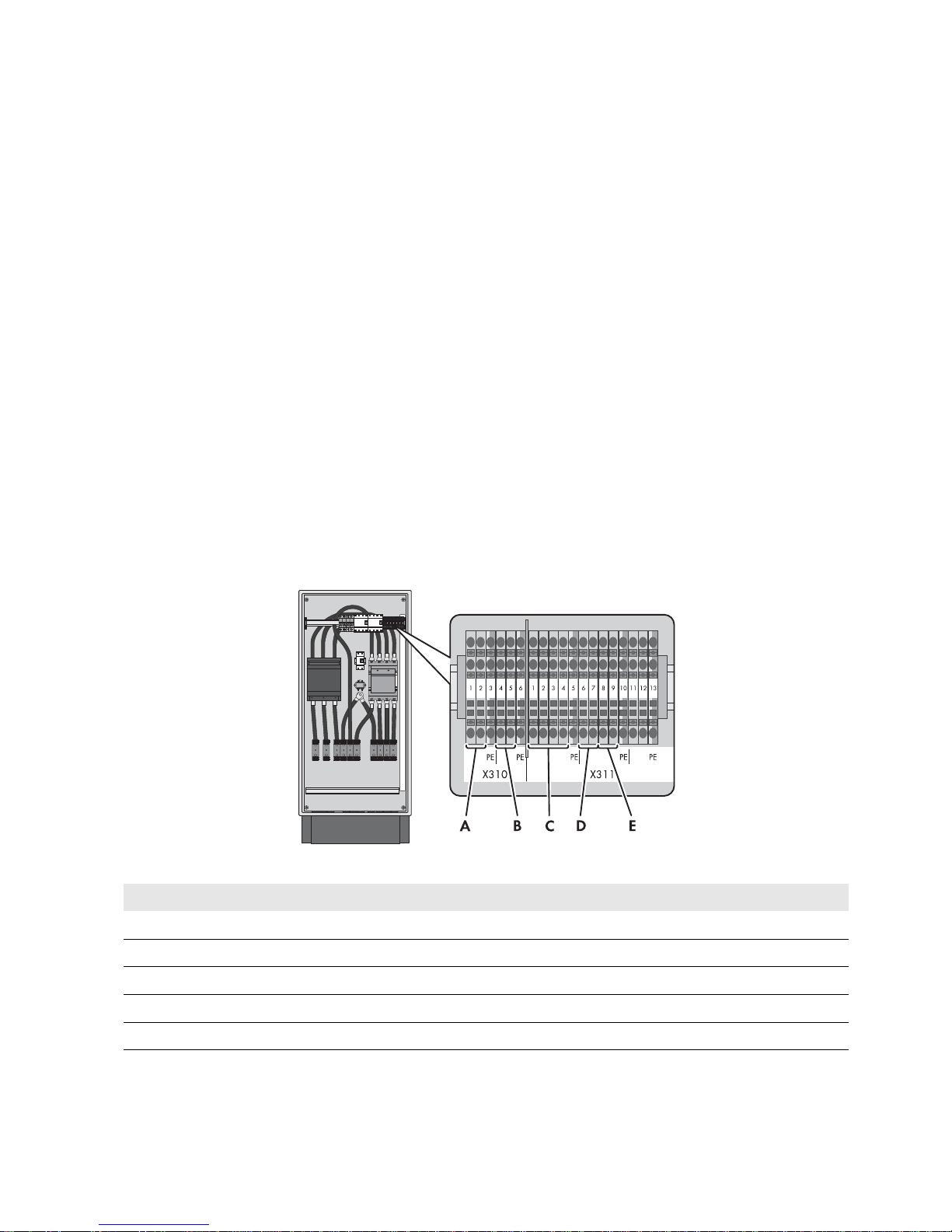
Figure10: Overview of spring-cage terminals in the Grid-Connect-Box
Position Explanation
A Multicluster-Box grounding contactor interlock (DC)
B Grid-Connect-Box grid contactor feedback (DC)
C Grid-Connect-Box voltage measurement (AC)
D Multicluster-Box generator contactor interlock (AC)
E Grid-Connect-Box AC contactor interlock (AC)

6 Electrical Connection SMA Solar Technology AG
20 GRID-BOX-12-3-20-BE-en-11 Operating Manual
Cable requirements:
Conductor material: copper
Conductor cross-section: 1.5 mm² to 2.5 mm²
The AC conductors and DC conductors must always be routed in separate cables.
Procedure:
1. Insert the control cables into the Grid-Connect-Box (see Section9.3, page25).
2. Connect the control cables to the spring-cage terminals (see Section9.4.2, page27).
•X310:1,2: Multicluster-Box grounding contactor interlock
•X310:4,5: Grid-Connect-Box grid contactor feedback
•X311:1-4: Grid-Connect-Box voltage measurement
•X311:6,7: Multicluster-Box generator contactor interlock
•X311:8,9: Grid-Connect-Box AC contactor interlock
3. Ensure that the insulated conductors are firmly in place.
6.6 Mounting the Kick Plates
Requirement:
All installation work must be completed.
Procedure:
1. Ensure that the power cables are secured with a strain relief.
2. Insert the kick plates and attach using the fastening screws (TX 30, torque: 12 Nm).
Ground connection at terminals X310 and X311
If the control cable between the Multicluster-Box and Grid-Connect-Box contains a grounding conductor, the
grounding conductor terminal must not be connected on both sides.
Table of contents
Other SMA Solar Technology AG Inverter manuals


