Prime IM-PT320 User manual
Ver. 1.0 / 2011.07
User’s Manual
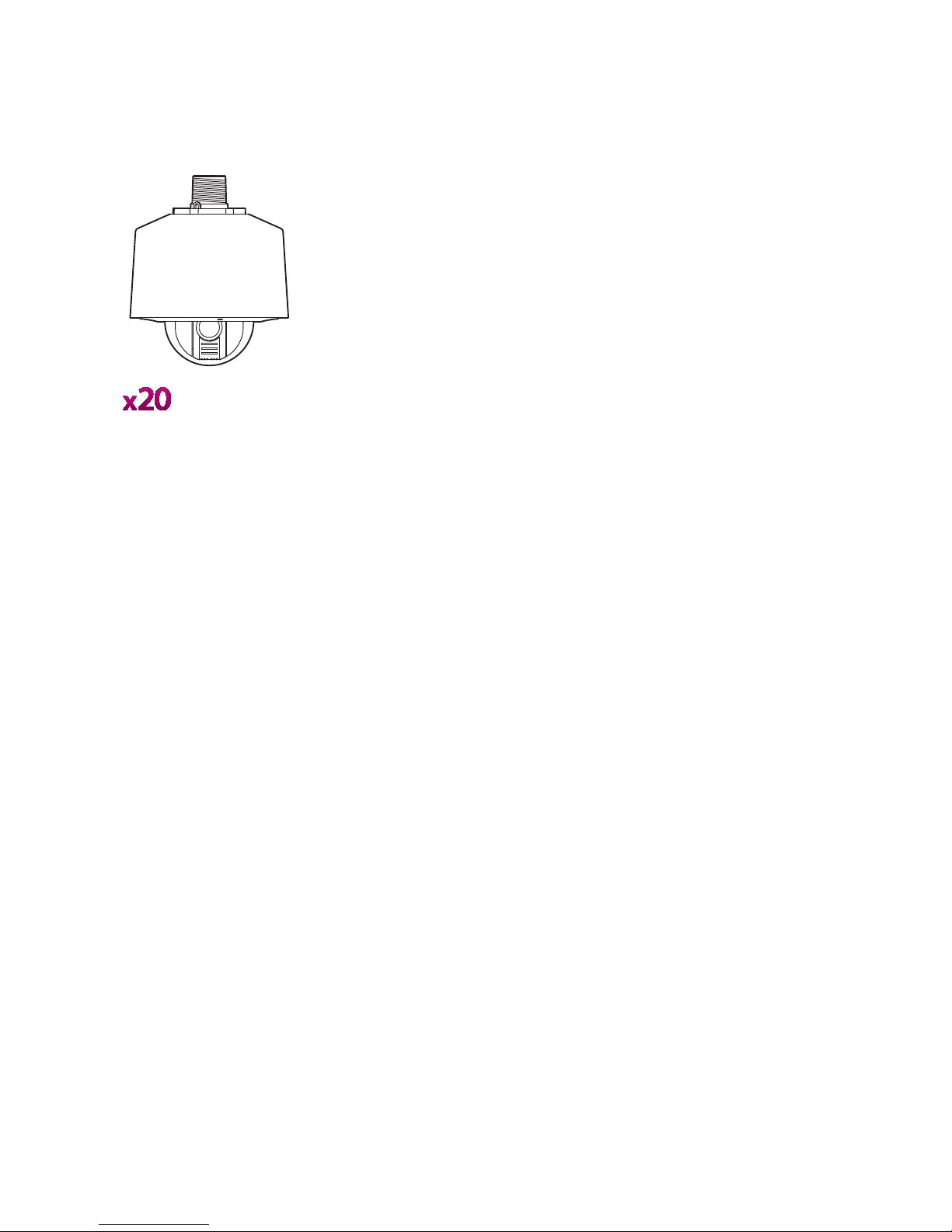
All-in-One Camera
Full-HD IP PTZ Outdoor
Safety Information
This symbol indicates that dangerous voltage
consisting a risk of electric shock is present within
this unit.
Warning Precaution
This exclamation point symbol is intended to alert the
user to the presence of important operating and
maintenance (servicing) instructions in the literature
accompanying the appliance.
TO REDUCE THE RISK OF ELECTRIC SHOCK, DO NOT REMOVE COVER (OR BACK) NO USER SERVICEABLE
PARTS INSIDE. REFER SERVICING TO QUALIFIED SERVICE PERSONNEL.
CAUTION:
CAUTION
RISK OF ELECTRIC SHOCK.
DO NOT OPEN.
To prevent damage which may result in fire or electric shock
hazard, do not expose this appliance to rain or moisture.
Be sure to use only the standard adapter that is specified in
the specification sheet. Using any other adapter could cause
fire, electrical shock, or damage to the product.
Incorrectly connecting the power supply or replacing battery
may cause explosion, fire, electric shock, or damage to the
product.
Do not connect multiple cameras to a single adapter.
Exceeding the capacity may cause abnormal heat generation
or fire.
Securely plug the power cord into the power receptacle.
Insecure connection may cause fire.
When installing the camera, fasten it securely and firmly.
A falling camera may cause personal injury.
Do not place conductive objects (e.g. screw drivers, coins,
metal things, etc.) or containers filled with water on top of
the camera. Doing so may cause personal injury due to fire,
electric shock, or falling objects.
Do not install the unit in humid, dusty, or sooty locations.
Doing so may cause fire or electric shock.
If any unusual smells or smoke come from the unit, stop
using the product. In such case, immediately disconnect the
power sorce and contact the service center. Continued use
in such a condition may cause fire or electric shock.
If this product fails to operate normally, contact the nearest
service center. Never disassemble or modify this product in
any way.
When cleaning, do not spray water directly onto parts of the
product. Doing so may cause fire or electric shock.
WARNING
WARNING
2.
3.
4.
5.
6.
7.
8.
9.
10.
11.
Precautions
Operating
t Before using, make sure power supply and others are
properly connected.
tWhile operating, if any abnormal condition or malfunction
is observed, stop using the camera immediately and then
tcontact your Special dealer.
Handling
tDo not disassemble or tamper with parts inside the camera.
tDo not drop or subject the camera to shock and vibration as
this can damage camera.
tCare must be taken when you clean the clear dome cover.
Especially, scratch and dust will ruin your quality of camera.
Installation and Storage
tDo not install the camera in areas of extreme temperature,
which exceed the allowable range.
tAvoid installing in humid or dusty places.
tAvoid installing in places where radiation is present.
tAvoid installing in places where there are strong magnetic
elds and electric signals.
tAvoid installing in places where the camera would be subject
to strong vibrations.
tNever expose the camera to rain and water.

Important Safety Instructions
1. Read these instructions. - All these safety and operating instructions should be read before the product is operated.
2. Keep these instructions. - The safety, operating and use instructions should be retained for future reference.
3. Heed all warnings. - All warnings on the product and in the operating instructions should be adhered to.
4. Follow all instructions. - All operating and use instructions should be followed.
5. Do not use this apparatus near water. - For example: near a bath tub, wash bowl, kitchen sink, laundry tub, in a
wet basement; near a swimming pool; etc.
6. Clean only with dry cloth. - Unplug this product from the wall outlet before cleaning. Do not use liquid cleaners.
7. Do not block any ventilation openings. Install in accordance with the manufacturer’s instructions. - Slots and
openings in the cabinet are provided for ventilation, to ensure reliable operation of the product, and to protect it
from over-heating. The openings should never be blocked by placing the product on bed, sofa, rug or other similar
surface. This product should not be placed in a built-in installation such as a bookcase or rack unless proper
ventilation is provided and the manufacturer’s unstructions have been adhere to.
8. Do not install near any heat sources such as radiators, heat registers, or other apparatus (including ampliers)
that produce heat.
9. Do not defeat the safety purpose of the polarized or grounding-type plug. A polarized plug has two blades with
one wider than the other. A grounding type plug has two blades and a third grounding prong. The wide blade
or the third prong are provided for your safety. If the provided plug does not t into your outlet, consult an
electrician for replacement of the obsolete outlet.
10. Protect the power cord from being walked on or pinched particularly at plugs, convenience receptacles, and
the point where they exit from the apparatus.
11. Only use attachments/accessories specied by the manufacturer.
12. Use only with cart, stand, tripod, bracket, or table specied by the
manufacturer, or sold with the apparatus. When a cart is used, use
caution when moving the cart/apparatus combination to avoid
injury from tip-over.
13. Unplug this apparatus during lightning storms or when unused for long periods of time.
14. Refer all servicing to qualied service personnel. Servicing is required when the apparatus has been damaged
in any way, such as power supply cord or plug is damaged, liquid has been spilled or objects have fallen into the
apparatus, the apparatus has been exposed to rain or moisture, does not operate normally, or has been
dropped.
Disposal of Your Old Appliance
1. When this crossed-out wheel bin symbol is attached to a product it mean the product is covered by
the European Directive 2002/96/EC.
2. All electrical and electronic products should be disposed of separately form the municipal waste
stream via designated by the government or the local authorities.
3. The correct disposal of your old appliance will help prevent potential negative consequences for
the environment and human health.
4. For more detailed information about disposal of your old appliance, please contact your city oce,
waste disposal service or the shop where you purchased the product.
This equipment has been tested and found to comply with the limits for a Class A digital device, pursuant to part 15 of the FCC Rules.
These limits are designed to provide reasonable protection against harmful interference when the equipment is operated in a commercial environment.
This equipment generates, uses, and can radiate radio frequency energy and, if not installed and used in accordance with the instruction manual, may cause
harmful interference to radio communications. Operation of this equipment in a residential area is likely to cause harmful interference in which case the user
will be required to correct the interferenece at his own expense.

Contents
6
7
8
10
15
17
18
19
20
21
22
23
24
25
26
27
28
29
30
31
32
33
34
35
36
39
40
42
43
44
45
46
47
48
49
50
51
52
53
54
55
56
57
58
59
60
61
62
63
64
65
66
68
69
70
71
Product & Accessories
Part Name & Functions
DIP Switch Setup
Installation Using Wall/Ceiling Mount Bracket
Cabling
Cabling the Audio Cable
Inserting/Removing an SD Memory Card
Quick Start of Network Connection
Initial Setup via a Crossover Cable
DDNS Registration
Guide to Network Environment
Setup Case A, B
Setup Case C, D
Port Forwarding
Starting IP Speed Dome
Basic Screen
PTZ Control
Etc. Control
Auto-map
Auto-map > Preset
Auto-map > Pattern
Auto-map > Scan
Auto-map > Group
Viewer Interface
Camera Setup
Setup Screen
Video Setup
Audio Setup
TCP/IP Setup
DDNS Setup
HTTPS
SNMP
Status
Alarm Input 1 Setup
Alarm Input 2 Setup
Motion Detection Setup
Schedule Setup
Auto Tracking Setup
Transfer Setup
FTP Setup
SMTP Setup
SD CARD Setup
Users Setup
Date/Time Setup
Firmware Update
Default Set
Restart
Log
Search
A : Current TCP/IP Settings
B : Changing IP address and subnet mask
C : Port Forwarding
FAQ
Dimension
Specification
Network Specification
1. Introduction
2. Installation
8. Appendix
9. Specifications
7. SD Card Search
3. Network Setup
4. Web Viewer Screen
5. Camera Setup
6. Setup

Product & Accessories
Introduction -
1
Wall Mount Type
Ceiling Mount Type
Housing Safety
Cable Hanger
Water Proof Tape
Hole Template
Hexagonal Wrench
Manual CD
Anchor Bolt(4pcs)
Safety Wire
102.0
142.0
Product Accessories
Quick Manual
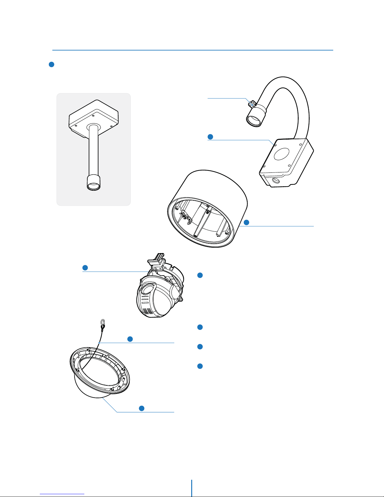
Part Name & Functions_Outside
Introduction -
1
1Wall Mount Bracket
1
2
2
5
3
3
4
5
Wall/Ceiling Mount Bracket
These are used to install the camera on the wall or ceiling
and have junction box. The junction box of the bracket
accommodate inner box.
Sun Shield & Upper Housing
4Dome Safety Wire
PTZ Mechanism
Dome Cover
Housing Safety
Wire Hanger
Ceiling Mount Bracket
Sunshield & Upper Housing
Sunshield protect bubble dome cover from the sun rays and
rain fall. In the sunshield, there is the upper housing which
will contain accommodate PTZ mechanism. In the upper
housing, there are fan and heater to remove moisture on
the bubble dome. Also, the upper housing will be
connected to both mounting brackets and dome cover.
PTZ Mechanism
Control the PTZ operations of the camera.
Dome Safety Wire
Prevents the dome cover from falling.
Dome Cover
Do not detach protection lm from dome cover before
finishing all installation process to protect dome cover from
scratches or dust.

8
Part Name & Functions_Inside
Introduction -
1
6
7
8
9
Heater
Defrost the dome cover in a low temperature by increasing
the internal temperature of the housing.
Audio Output Port
Used to connect the audio output cable.
Audio Input Port
Used to connect the audio input cable.
Micro SD Memory Card Slot & Cover
Power Port
Connect the power source here.
1
2
3
4
5
2nd Video Output Port
Video out check the screen during installation.
Alarm In/Output and 2nd Video Output Port
It connects to the alarm lights, siren or lamps, and it is
activated according to the OSD menu or ‘Setup’ on the Web
-viewer setting. And 2nd video output use to check
the screen during installation.
Network Cable Port
Connect the crossover cable.
Fan
Defrosts the dome cover and removes moisture.
Alarm In/Output and
2nd Video Output Port
Network Cable Port
Fan
Heater
Audio Output Port
Audio Input Port
Micro SD Card Slot
& Cover
2
1
3
4
5
6
7
8
9Power Port
2nd Video Output Port

Installation -
Installation Using Wall/Ceiling Mount Bracket
2
2
1
3
Using the hole template, mark the holes on the wall/ceiling.
After drilling the holes, fix the four anchor bolts into the
holes.
After locating the wall/ceiling mount bracket on the anchor
bolts properly, tighten the nuts for anchor bolts.
Ceiling Mount Bracket
Installation
Wall Mount Bracket
Installation
Installation
Installation -
2
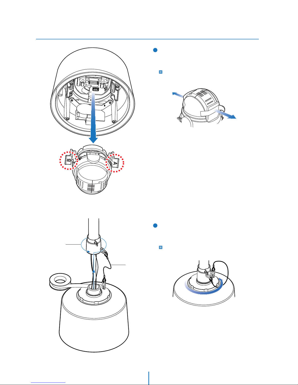
4You have to detach the PTZ mechanism from the upper
housing to plug the connector of cable. When detach PTZ
mechanism, pressing down and holding up the black
handles in both sides of PTZ mechanism.
You should remove the tape used to fix the PTZ
mechanism after detaching the PTZ mechanism from
the upper housing.
5[1] Wind the water proof tape on the pipe of upper housing.
[2] Hooking the safety wire on the hole of pipe.
[3] Attach the upper housing to wall mount bracket by
turning it at least seven turns.
To fix the upper body orientation, turn the handle of
double nuts to clockwise tightly.
[2]
[1]
[3]
Table of contents


