Primex Wireless SNS2TPS-2 User manual

SNS™ Temperature and Humidity Sensors
Installation Guide
Document Part No.: SNSDOC-012
10/17/2011

Primex Wireless, Inc. SNS™ Temperature and Humidity Sensors Installation Guide 2
SNS™ Temperature and Humidity Sensors Installation Guide
Product Models
US: SNS2TPS-2, SNS2TPD-2, SNS2TNS-2, SNS2THS-2, SNSATPS, SNSATPD, SNSATHX
UK: SNS2TPS-2, SNS2TPD-2, SNS2TNS-2, SNS2THS-2, SNSGTPS, SNSGTPD, SNSGTHX
EU: SNS2TPS-2, SNS2TPD-2, SNS2TNS-2, SNS2THS-2, SNSCTPS, SNSCTPD, SNSCTHX
Legal Notice
Copyright ©2011 Primex Wireless, Inc. All rights reserved.
SNS is a trademark of Primex Wireless, Inc.
U.S. Patents 6,873,573; 7,352,657. Other Patents Pending.
Printed in the USA.
Reference Documentation
Note: Reference documentation is located on the SNS Resource CD (Q13140) and in the
Support area of the SNS AMP software.
SNS™ Temperature and Humidity Sensors User Guide (SNSDOC-006)
SNS™ AMP Installation and Administration Guide (SNSDOC-005)
Contact Primex Wireless
Web: http://www.primexwireless.com/
E-mail: support@primexwireless.com
United States
Canada
United Kingdom
Telephone
(800) 404-8112
(800) 404-8112
0800-3896996
Hours
7:00am - 5:00pm Central
7:00am - 5:00pm Central
8:30am – 5:00pm GMT
Fax
(262) 248-0061
(905) 952-0134
01422-349462

Primex Wireless, Inc. SNS™ Temperature and Humidity Sensors Installation Guide 3
Contents
Safety Precautions .............................................................................................................................. 5
Safety Precautions.............................................................................................................................5
Equipment Precautions......................................................................................................................5
About this Guide.................................................................................................................................. 6
Documentation Overview...................................................................................................................6
Guide Conventions.............................................................................................................................6
Introducing SNS™ Temperature and Humidity Sensors................................................................... 7
Sensor Devices and Accessories.......................................................................................................7
Overview of SNS Sensor Network Installation....................................................................................9
Network Requirements for SNS Sensor Devices............................................................................. 11
Wireless Signal ................................................................................................................................11
Wireless Security..............................................................................................................................11
Network Protocol and Ports..............................................................................................................11
Features of SNS AC-powered Sensor Devices................................................................................ 12
Network, Power, and Probe Connections.........................................................................................12
Service Button..................................................................................................................................12
Visual and Auditory Interfaces..........................................................................................................13
Monitoring Thresholds......................................................................................................................15
Operational Sequences....................................................................................................................15
Features of SNS Battery-powered Sensor Devices......................................................................... 18
On/Off Switch...................................................................................................................................18
Batteries...........................................................................................................................................19
Programming Cable Connection.......................................................................................................19
Probe Connections...........................................................................................................................20
Service Button..................................................................................................................................20
Visual and Auditory Interfaces..........................................................................................................21
Monitoring Thresholds......................................................................................................................22
Operational Sequences....................................................................................................................23
Configure Sensors for the Network.................................................................................................. 25
Select the Configuration Method ......................................................................................................25
Edit Default Sensor Profiles..............................................................................................................25
Configure AC-powered Sensors using Discovery and Auto-Configuration........................................ 31
Set up the Network Connection........................................................................................................32
Configure AC-powered Sensors using Browser-based Configuration...............................................34
Configure Battery-powered Sensors with the Sensor Configuration Utility........................................39
Install SNS Sensor Devices and Accessories.................................................................................. 47
Install SNS Temperature and Humidity Sensors...............................................................................47
Install a Thermobuffer ......................................................................................................................47
Maintain Sensor Devices................................................................................................................... 49
Replace Batteries in Battery-powered Sensor Devices.....................................................................49

Contents
Primex Wireless, Inc. SNS™ Temperature and Humidity Sensors Installation Guide 4
Troubleshoot Sensors....................................................................................................................... 50
Troubleshooting AC-powered Sensors.............................................................................................50
Troubleshooting Battery-powered Sensors.......................................................................................50
Appendix A: Browser-based Configuration Tool............................................................................. 54
Action Buttons..................................................................................................................................54
Appendix B: Battery Sensor Configuration Utility........................................................................... 57
Installing the Configuration Utility .....................................................................................................57
User Interface...................................................................................................................................60
Appendix C: Regulatory Compliance............................................................................................... 71
FCC Compliance..............................................................................................................................71

Primex Wireless, Inc. SNS™ Temperature and Humidity Sensors Installation Guide 5
Safety Precautions
Read this document thoroughly before performing any installation or service procedures.
Safety Precautions
SNS sensors are designed for indoor use only and are not weather protected. Operating the
sensors outdoors, or in wet areas is an electrical hazard and may damage the temperature sensor
while nullifying the warranty.
Equipment Precautions
•To avoid possible electric shock or damage to an SNS sensor, make sure that it is not powered
when mounting it.
•For healthcare facilities, sensors are not intended for patient use and must not be installed
within 6ft (2m) of patient contact.
•SNS sensors may be cleaned with a cloth moistened with water or a common disinfectant.
Be sure to test any cleaning solutions on a small area of the
sensor before using it on the entire sensor.

Primex Wireless, Inc. SNS™ Temperature and Humidity Sensors Installation Guide 6
About this Guide
Documentation Overview
Depending on your function(s), you will find the following documents most helpful:
I am… I want to… Document I need…
Installing the SNS AMP
Server and Software •Install the AMP
•Put the AMP on the network
•Set time on the AMP
•Add AMP Users and Assign
Roles
•Configure Network and Time
Settings
•Install Sensor Licenses
•Manage Background Jobs
SNS AMP Quick Start Guide
SNS AMP Installation and
Administration Guide
Adding Sensors to the
Network •Create Default Profiles
•Configure Sensors SNS Temperature and Humidity
Sensors Installation Guide
Installing Sensors •Mount Sensors
•Use a Thermobuffer SNS Temperature and Humidity
Sensors Installation Guide
Using Sensors •Modify Temperature and
Humidity Thresholds
•Handle Alarms
SNS Temperature and Humidity
Sensors User Guide
Managing, Monitoring, and
Reporting on Sensors •Manage Sensors
•Monitor Sensors
•View and Print Sensor
Reports
SNS Temperature and Humidity
Sensors User Guide
Maintain Sensors •Upgrade Sensor Firmware
•Change Batteries SNS Temperature and Humidity
Sensors User Guide
Guide Conventions
This guide uses typographical conventions to highlight specific types of information.
Information Example
Graphical user interface tab and menu sequence. Choose Sensors > Auto-Config.
Graphical user interface pages and controls. Return to the Sensor Devices page. Click Save.
Command line input. Type the following:
>
cd /var/sns/sns-install
User-specified input. Open a browser to http:your.amp.address.com.
Primex Wireless, Inc. SNS™ Temperature and Humidity Sensors Installation Guide 7
Introducing SNS™ Temperature and Humidity Sensors
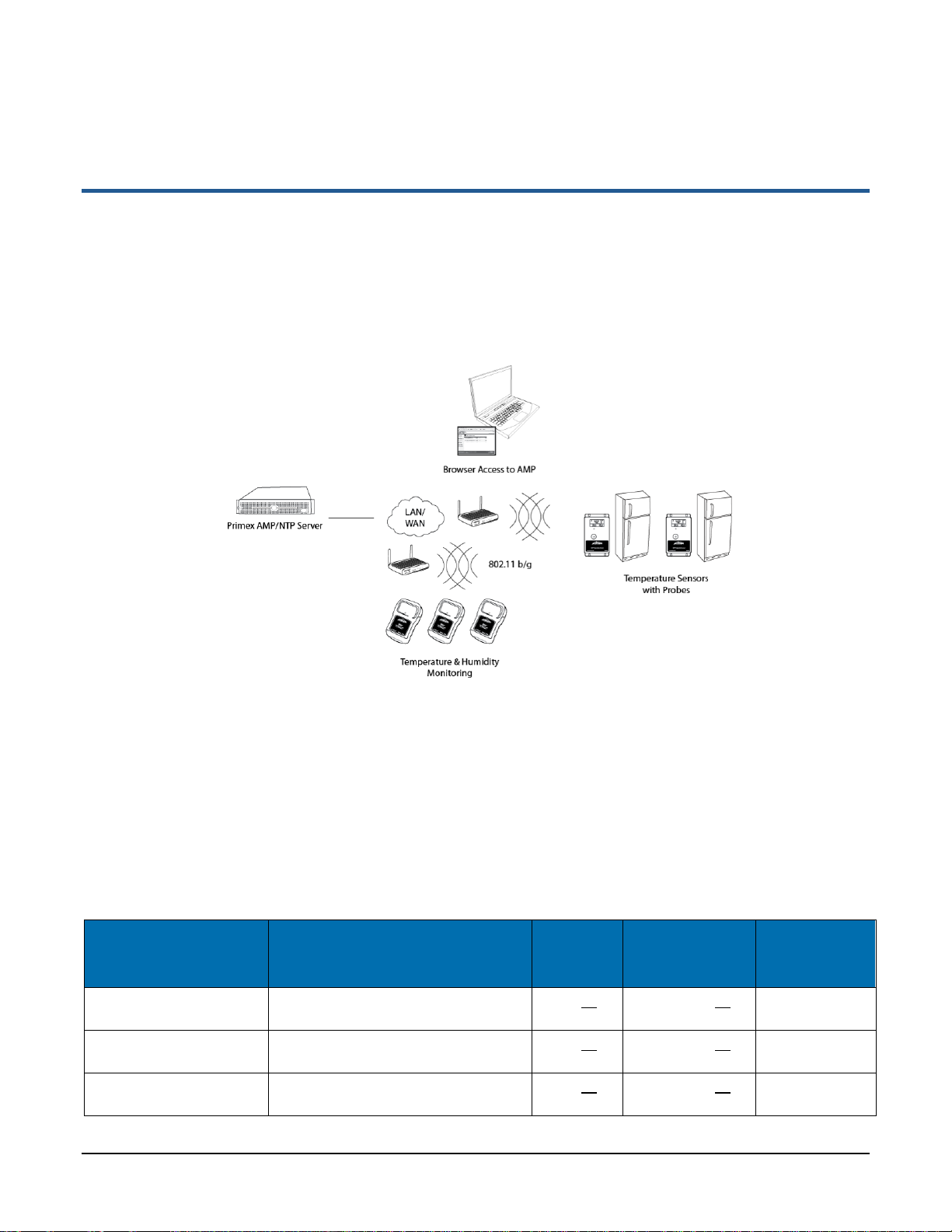
SNS™ Temperature and Humidity Sensors provide monitoring and logging of environmental
conditions throughout your facilities. SNS Temperature and Humidity Sensors (sensor devices)
communicate with the Synchronized Network Solutions (SNS) Application Management Platform
(AMP)/Network Time Protocol (NTP) server over wireless 802.11 b/g networks. (Some sensor
devices can also communicate over the wired Ethernet network.) Figure 1 shows the architecture of
an SNS Temperature and Humidity Sensors network.
Figure 1: SNS Temperature and Humidity Sensors Network
Sensor Devices and Accessories
Primex Wireless offers battery- and AC-powered sensor devices and probes. An important
accessory for both AC- and battery powered external probe sensors is the SNS thermobuffer, which
enables sensor readings to be based on the temperature of the refrigerated assets rather than on
the air temperature.
AC-powered Sensor Devices and Accessories
Table 1 and Table 2 describe the AC-powered sensor devices and accessories. For more on AC-
powered sensor devices, see Features of SNS AC-powered Sensor Devices on page 12.
Table 1: AC-powered Sensor Device Specifications
Sensor Device Part
Number Sensor Device Description Input
Power Current Draw Sensor Device
Operating
Range
SNSATPD Dual probe temperature sensor 6-12V--- 300mA@9V--- 32°F to 95°F
(0°C to 35°C)
SNSATPS Single probe temperature sensor 6-12V--- 300mA@9V--- 32°F to 95°F
(0°C to 35°C)
SNSATHX Temperature and humidty sensor 6-12V--- 300mA@9V--- 32°F to 95°F
(0°C to 35°C)

Introducing SNS™ Temperature and Humidity Sensors Sensor Devices and Accessories
Primex Wireless, Inc. SNS™ Temperature and Humidity Sensors Installation Guide 8
Table 2: AC-powered Single and Dual Probe Sensor Device Accessories
Accessory Part
Number Accessory Description Probe Operating Range
SNS6C1 Thermistor, AC temperature sensor (⅛”
probe) -22°F to 194°F (-30°C to 90°C)
SNS6C2 Thermistor, NIST Traceable AC
temperature sensor (¼” probe), -22°F to 194°F (-30°C to 90°C)
Q13563-1 25’ Thermistor Extension Cable Minor loss in accuracy in above when
extension cables are used
Q13563-2 50’ Thermistor Extension Cable Minor loss in accuracy in above when
extension cables are used
Battery-powered Sensor Device Specifications
Table 3 and Table 4 describe the battery-powered sensor devices and accessories.
Table 3: Battery-powered Sensor Device Specifications
Sensor Device Part
Number Sensor Device Description Input
Power Sensor Device Operating Range
SNS2TPS-2 Single probe, dual battery
temperature sensor 2 AA
batteries -40°C-85°C
SNS2TPD-2 Dual probe, dual battery
temperature sensor 2 AA
batteries -40°C-85°C
SNS2TNS-2 Sealed, dual battery temperature
sensor 2 AA
batteries -40°C-60°C
SNS2THS-2 Dual battery temperature and
humidity sensor 2 AA
batteries -40°C-60°C
Table 4: Battery-powered Sensor Device Accessories
Accessory Part
Number Accessory Description Probe Operating Range
SNS6AC4 Standard 4” RTD Probe, 6’ Teflon Cable -50°C to 125°C
SNS2AC4 Standard 4” RTD Probe, 2’ Teflon Cable -50°C to 125°C
SNS6BC4 Cryo 4” RTD Probe, 6’ Sheathed Teflon
Cable -200°C to 125°C
SNS2BC4 Cryo 4” RTD Probe, 2’ Sheathed Teflon
Cable -200°C to 125°C
Q13332 USB Programming Cable N/A
SNS888 AA Lithium Battery 1.5v N/A

Introducing SNS™ Temperature and Humidity Sensors Overview of SNS Sensor Network Installation
Primex Wireless, Inc. SNS™ Temperature and Humidity Sensors Installation Guide 9
SNS Thermobuffers
A thermobuffer can be used with battery- and AC-powered single and dual probe temperature
sensors to simulate the actual temperature of contents within coolers or freezers. The thermobuffer
is a bottle of food-grade glycol into which the temperature probe is placed inside the refrigerator.
The thermobuffer simulates refrigerated items, which change temperature more slowly than the air
when the refrigerator door is opened. Using a thermobuffer with sensor devices limits the impact of
fluctuating air temperature on sensor readings and helps provide a higher degree of measurement
accuracy. The thermobuffer is effective to a minimum temperature of -27° F.
Table 5: SNS Thermobuffer Accessories
Accessory Part Number Accessory Description
SNSGRP SNS Thermobuffer, 4 oz. Glycol Bottle for RTD Probe and Thermistor (NIST)
SNSGLY-1 1 Gallon Food Grade Glycol
Overview of SNS Sensor Network Installation
Prerequisites to SNS Sensor Installation
The following tasks must be complete before installing SNS Sensors.
•Install and set up the SNS Application Management Platform (AMP)/Network Time Protocol
(NTP) server.
•Enter the SNS Sensors license key in the AMP.
•Assign the Sensor Admin role to the AMP administrator or other user login.
This installation guide assumes that the AMP and Sensors license are installed and that you can
log in to the AMP as a user with the Sensor Admin role. See the SNS AMP Installation and
Administration Guide and the SNS Temperature and Humidity Sensors User Guide for details.
Plan the Installation
Sensor device installation begins by planning where to place sensor devices and ensuring that the
wireless or wired network is available at these locations.
Note: Sensor devices must have adequate signal to support wireless operation. Sensor
devices will work in areas where a wireless laptop can connect to the network or
where signal to noise level measures 20 dB or greater. If wireless signal is
inadequate, a wireless Access Point may be added in proximity to improve local
signal strength. AC-powered sensor devices can also be connected to the
Ethernet network via the RJ45 connector.
Configure Sensor Devices for the Network
Sensor devices arrive at your facility with no knowledge of the network. The next step in installing
the SNS Sensors network is to configure sensor devices. See Configure Sensors for the Network
on page 25 for details.
Install and Verify Sensor Devices
Once sensors are configured and you know they can connect to the network, they are ready for
installation in their permanent locations. See Install SNS Sensor Devices and Accessories on page
47 for details.

Introducing SNS™ Temperature and Humidity Sensors Overview of SNS Sensor Network Installation
Primex Wireless, Inc. SNS™ Temperature and Humidity Sensors Installation Guide 10
View and Update Sensor Device Information in the AMP
During sensor device configuration and upon installation, you will use AMP screens to verify that
the sensor device is communicating with the AMP. You will also use AMP pages to enter
information, such as the location of the sensor device or alerting thresholds. See the SNS
Temperature and Humidity Sensors User Guide for details.

Primex Wireless, Inc. SNS™ Temperature and Humidity Sensors Installation Guide 11
Network Requirements for SNS Sensor Devices
SNS Temperature and Humidity Sensors work on 802.11 b/g wireless networks. Some sensors also
work on wired Ethernet networks. This section describes the requirements for the SNS
Temperature and Humidity Sensors network.
Wireless Signal
Sensor devices must have adequate signal to support wireless operation. Sensor devices will work
in areas where a wireless laptop can connect to the network or where signal to noise level
measures 20 dB or greater. If wireless signal is inadequate, a wireless Access Point may be added
in proximity to improve local signal strength. AC-powered sensor devices can also be connected to
the Ethernet network via the RJ45 connector.
Wireless Security
AC-powered Sensor Devices
AC-powered sensor devices support WEP, WPA, and WPA2 encryption standards with LEAP,
EAP-FAST, and PEAP authentication.
Battery-powered Sensor Devices
Battery-powered sensor devices support WEP - 128, WPA-TKIP, and WPA2-AES encryption
standards.
Network Protocol and Ports
AC-powered Sensor Devices
AC-powered sensors send sensor device data via UDP packets. Ports 1600 and 1640 must be
open on the network for data transmission and configuration.
Battery-powered Sensor Devices
Battery-powered sensors send sensor device data via UDP packets. Port 6767 must be open on
the network. Packets are small (less than 75 bytes).
Primex Wireless, Inc. SNS™ Temperature and Humidity Sensors Installation Guide 12
Features of SNS AC-powered Sensor Devices
This section contains the following topics:
•Network, Power, and Probe Connections
•Service Button
•Visual and Auditory Interfaces
•Monitoring Thresholds
•Operational Sequences
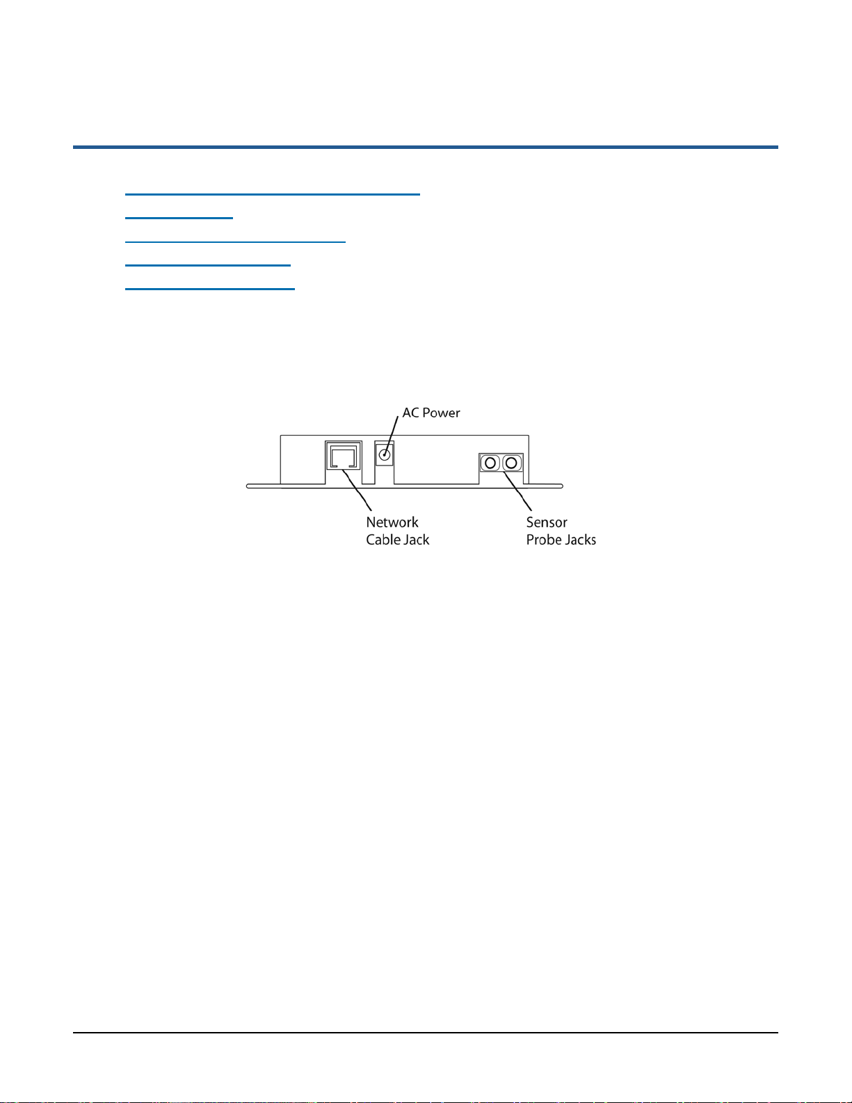
Network, Power, and Probe Connections
Network, power, and probe connections are located on the side of AC-powered sensors, as shown
in Figure 2. Dual-probe sensor devices contain two probe jacks.
Figure 2: Network, Power, and Probe Connections on AC-Powered Temperature Sensor (SNSATPD)
Network Connection
The RJ-45 network connection allows you to connect a standard Ethernet cable to the sensor
device. The network connection is used during browser-based configuration and if the sensor
device is configured to operate on the wired Ethernet network. For details on configuration, see
Configure Sensors for the Network on page 25.
AC-Power Connection
AC-powered sensor devices come with a power supply. Plugging in the power supply and
connecting it to the sensor device turns on the sensor device. AC-powered sensor devices must be
connected to AC power for normal operation.
Probe Connection(s)
AC-powered temperature sensor devices have one or two probe connections depending on the
sensor device model.
Service Button
The service button is located on the front of AC-powered sensor devices, as shown in Figure 3.

Features of SNS AC-powered Sensor Devices Visual and Auditory Interfaces
Primex Wireless, Inc. SNS™ Temperature and Humidity Sensors Installation Guide 13
Figure 3: Service Button, Display, and LED on AC-Powered Temperature Sensor (SNSATPD)
The service button has several uses depending on the status of the sensor device.
•To enable browser-based configuration, pressing and holding the service button while plugging
in the sensor device causes the device to enter configuration mode.
•During normal operation and discovery and auto-configuration, pushing the service button
causes the sensor device to sound the beeper and check in with the AMP.
•During an alarm, pushing the service button cancels the alarm and stops the LED from flashing
but does not acknowledge the alarm on the AMP. Pushing the service button during an alarm
also does not sound the beeper or cause the sensor device to check in with the AMP.
Visual and Auditory Interfaces
The display and LED, shown in Figure 3, are visual indicators of sensor device status and sensor
readings. The sensor device also communicates its status using beeps.
Display
Table 6 describes the display functions for AC-powered sensor devices.
Table 6: AC-powered Sensor Device Display
Item Description
38.1° F
65%RH Current reading of probe. For dual probe sensors, the reading alternates between
showing the reading of probe 1 and probe 2 every three seconds. Numbers ‘1’ and ‘2’ in
the upper left corner of the display indicate which reading is displayed. Before the display
changes to show the other probe’s temperature, both probe inputs are sampled.
MIN °F
32.0 Latest min and max temperature values. The min and max temperatures on the display
are checked every time a new sample is taken. The min and max on the display are a
daily min and max and every 24 hours from power up the daily min and max will be
cleared and replaced by the first sample of the next 24 hour period.
MAX °F
40.0

Features of SNS AC-powered Sensor Devices Visual and Auditory Interfaces
Primex Wireless, Inc. SNS™ Temperature and Humidity Sensors Installation Guide 14
Item Description
MIN %RH
75.0 Latest min and max relative humidity values. The min and max relative humidity on the
display are checked every time a new sample is taken. The min and max on the display
are a daily min and max and every 24 hours from power up the daily min and max will be
cleared and replaced by the first sample of the next 24 hour period.
Temperature and Humidity sensors only.
MAX %RH
60.0
dIS One of the probes is disconnected from the device. If the probe was never plugged in
since power up, no min or max will be shown until a probe is connected, though the
device will continue to check in with the AMP at its normal interval.
Temperature sensors only.
LO Temperature below -40 °C. No temperature sample is taken or stored, though the device
will continue to check in with the AMP at its normal interval. If the temperature drops much
further below -40 °C the display will change from LO to SHr.
Temperature sensors only.
HI Temperature above 90 °C.
Temperature sensors only.
SHr One of the probe inputs is shorted. No temperature sample is taken or stored, though the
device will continue to check in with the AMP at its normal interval. If the probe input was
short since power up, no min or max will be displayed until the short is removed.
Temperature sensors only.
CON Device is in configuration mode.
LO AC
(Appears
instead of
MIN/MAX or
%RH)
Device is running on backup power. When running on backup power, the device slows its
display rate and probe sampling rate down from every three seconds to every 15 seconds
to conserve power. To save power, the radio, LED, and buzzer are never turned on in this
mode.
LED
The LED has several meanings depending on the status of the sensor device.
•When an alarm is active, the LED on AC-powered sensors flashes once per second. Pushing
the service button when the LED is flashing stops the flashing but does not acknowledge the
alarm on the AMP.
•When in Find mode, the LED flashes rapidly 3 times per second. For information on Find mode,
see the SNS Temperature and Humidity Sensors User Guide.
•When powered up, the LED illuminates briefly.
Beeps
When the service button is pushed during normal operation, the sensor device emits two beeps and
activates the radio to contact the AMP. Once a successful exchange with the AMP occurs, the
device sounds the following series of beeps:
•1 beep indicates that the radio booted.
•2 beeps indicate that the sensor device has connected to network.
•3 beeps indicate that the sensor device has connected to the AMP. Connecting to the
AMP usually takes about 25 seconds assuming a standard wireless connection with
WPA2 security.

Features of SNS AC-powered Sensor Devices Monitoring Thresholds
Primex Wireless, Inc. SNS™ Temperature and Humidity Sensors Installation Guide 15
Buzzer
AC-powered sensor devices are equipped with an alarm buzzer. When an alarm is active, the
buzzer sounds continuously, if Enable Audio Alerts is enabled (checked) on the sensor device’s
Edit Sensor Device page in the AMP. Pushing the service button when the buzzer is sounding
silences the buzzer but does not acknowledge the alarm on the AMP.
Monitoring Thresholds
AC-powered sensor devices permit you to set temperature and humidity monitoring thresholds. If
the thresholds are exceeded or, depending on the configuration, exceeded for a period of time, the
sensor device enters an alarm state. To set monitoring thresholds and download them to the sensor
device, you edit sensor device information on the AMP. See the SNS Temperature and Humidity
Sensors User Guide for information on editing AC-powered sensor devices, including monitoring
thresholds.
Operational Sequences
Turn on the Sensor Device
Plugging in an AC-powered sensor turns the device on. When the device is first powered up, it will
turn on all of the LCD digits and the red LED. After 1 second, the display will briefly blank out and
the LED will be turned off. The device will then read all of its configuration data out of non-volatile
memory. If the device has never checked into an AMP, the default settings will be used. The default
settings are:
•Check-in Interval: 1 hour
•Temperature Display: Fahrenheit
•Alarms: None
After the configuration data is loaded, both probes inputs are sampled and the display begins
showing the temperature. The device then turns on its radio and proceeds to communicate with the
AMP.
Normal Operation
Single probe temperature sensor devices update the probe reading every three seconds. Dual
probe temperature sensor devices alternate between showing the temperature of probe 1 and
probe 2 every three seconds, while temperature and humidity sensor devices alternate between
showing temperature and humidity every three seconds. Before the display changes to show the
other reading, both inputs are sampled. The min and max temperatures on the display are checked
every time a new temperature sample is taken. The min and max on the display are a daily min and
max and every 24 hours from power up the daily min and max will be cleared and replaced by the
first sample of the next 24 hour period.
Check-in with the AMP
The sensor device checks in with the AMP at regular intervals (default 1 hour), starting when the
device is powered up. If a check in with the AMP fails, the information is stored in non-volatile
memory. The non-volatile memory is capable of storing 2046 readings. If the number of failed
check-ins exceeds the size of the non-volatile memory, the oldest readings are overwritten. Any
data stored in non-volatile memory will be lost if the device loses both AC and backup power.

Features of SNS AC-powered Sensor Devices Operational Sequences
Primex Wireless, Inc. SNS™ Temperature and Humidity Sensors Installation Guide 16
Pushing the service button during normal operation forces the sensor device to check in with the
AMP. When the service button is pressed, the sensor device will emit a series of beeps. The beeps
signal the following connection sequence: 1= radio booted, 2 = connected to network, 3 =
connected to the AMP (usually takes about 25 seconds to hear the beep assuming a standard
wireless connection with WPA2 security).
Configuration Mode
Holding the button down while plugging the device in causes the device to enter configuration
mode, regardless of whether it has been configured previously.While in configuration mode, you
can perform browser-based configuration. When the device first enters configuration mode, it beeps
once. This beep indicates to the user that they can take their finger off the button. While in
configuration mode, the device flashes CON for one second and then goes blank for the next
second. The sensor device continues to flash CON while in configuration mode. See Configure
Sensors for the Network on page 25 for information on configuration.
Handle Alarms
When an alarm is active, the LED on the front of the sensor device flashes once per second and the
buzzer sounds continuously, if Enable Audio Alerts is enabled (checked) on the sensor device’s
Edit Sensor Device page in the AMP.
If an alarm is active (LED is flashing), pushing the button cancels the alarm and stops the LED from
flashing, but does not acknowledge the alarm on the AMP. Pushing the button during an alarm also
does not sound the beeper or cause the sensor device to check in with the AMP.
The behavior of the sensor device after cancelling an alarm depends on how the device is
configured in the sensor device’s Edit Sensor Device page:
•If a threshold has been exceeded with High Span Minutes blank and Audio Reset Period set at
Indefinite, pushing the button cancels the alarm and an alarm will not occur again until the
sensor goes back in range and then out of range again.
•If a threshold has been exceeded with the Audio Reset Period is configured but High Span
Minutes is blank, the alarm does not sound again until the Audio Reset Period expires.
•If a Span Minutes has been exceeded, pushing the button cancels the alarm. If the device
remains out of range and if an Audio Reset Period is configured, the alarm will not sound again
until the Audio Reset Period expires.
•If a Span Minutes has been exceeded, pushing the button cancels the alarm. If an Audio Reset
Period is not configured, the alarm sounds again once Span Minutes runs out a second time.
Backup Power
AC-powered sensor devices have an internal super cap that allows the devices to continue to do
many of their functions during an AC power outage. It normally takes about 8 hours to fully charge a
super cap. Once fully charged, an AC-powered sensor device should be able to run on backup
power for up to 4 hours.
All data being collected by the probes is stored in non-volatile memory. This data will be lost if
backup power fails. If AC power is restored before backup power fails and the temperature stayed
within the set limits, all of the readings will be sent to the AMP as a single check in with the current
temperature for the entire duration of the power outage. If a high or low limit is crossed while
running on backup power, the data will be saved to non-volatile memory with a timestamp. This

Features of SNS AC-powered Sensor Devices Operational Sequences
Primex Wireless, Inc. SNS™ Temperature and Humidity Sensors Installation Guide 17
data will be erased in the event that backup power fails. If it does not fail, these archived readings
will be sent to the AMP as well as current temperature readings when AC power is restored so that
you may see when temperatures went in and out of limits and for what duration. In the AMP Sensor
Readings page, archived readings appear with a check mark in the Logged Readings column and
have the same Transmit Count as the current reading.
Primex Wireless, Inc. SNS™ Temperature and Humidity Sensors Installation Guide 18
Features of SNS Battery-powered Sensor Devices
This section contains the following topics:
•On/Off Switch
•Batteries
•Programming Cable Connection
•Probe Connections
•Service Button
•Visual and Auditory Interfaces
•Monitoring Thresholds
•Operational Sequences
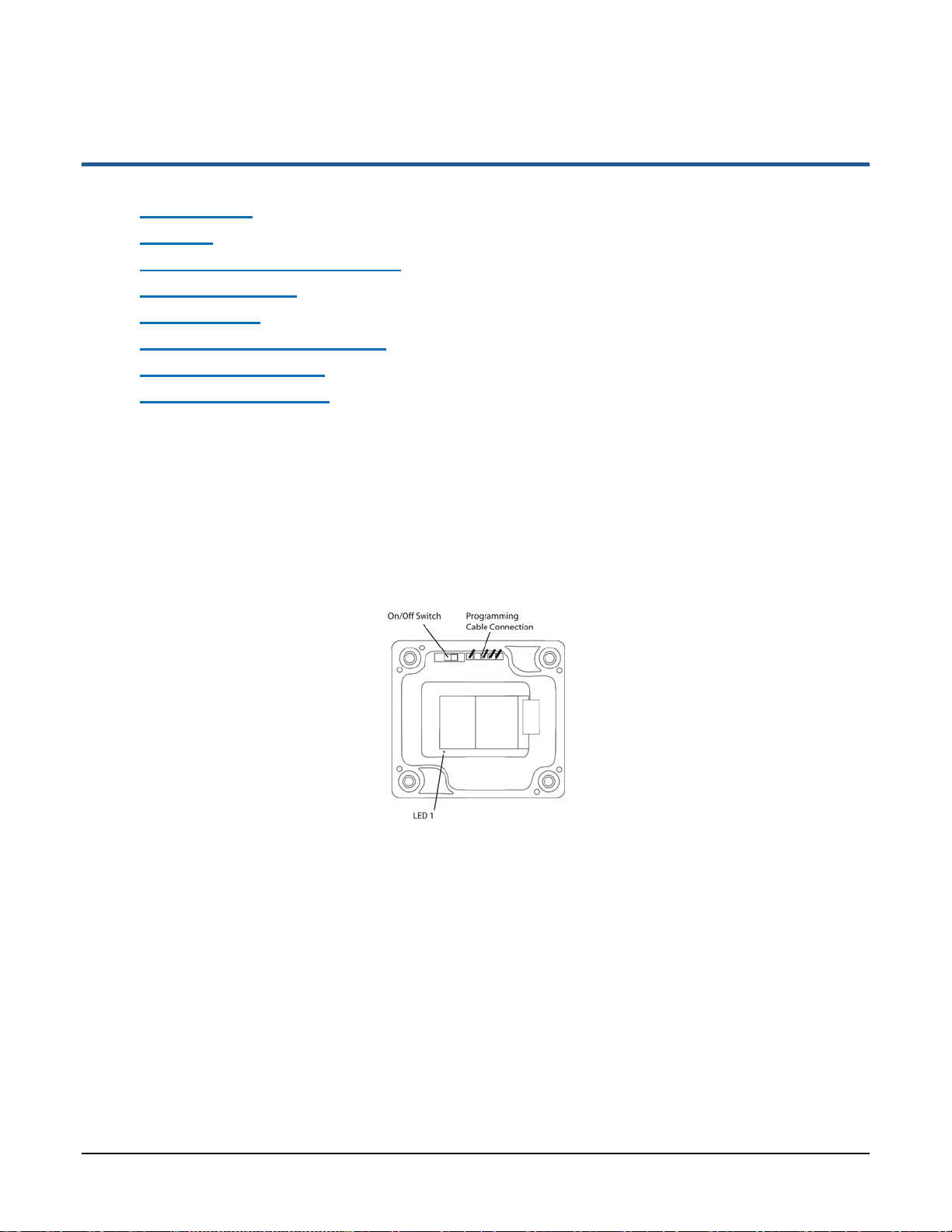
On/Off Switch
Battery-powered sensor devices have on/off switches. The sensor devices must be turned on
during configuration and normal operation. As shown in Figure 4, the on/off switch on model
SNS2TNS-2 is located inside the sensor device. On this model, moving the switch away from the
programming cable connection turns the sensor device on. On model SNS2TPS-2, the on/off switch
is located in the battery compartment, as shown in Figure 5. On model, SNS2THS-2, it is on the
side (Figure 6). Figure 4: Inside Model SNS2TNS-2
Features of SNS Battery-powered Sensor Devices Batteries
Primex Wireless, Inc. SNS™ Temperature and Humidity Sensors Installation Guide 19
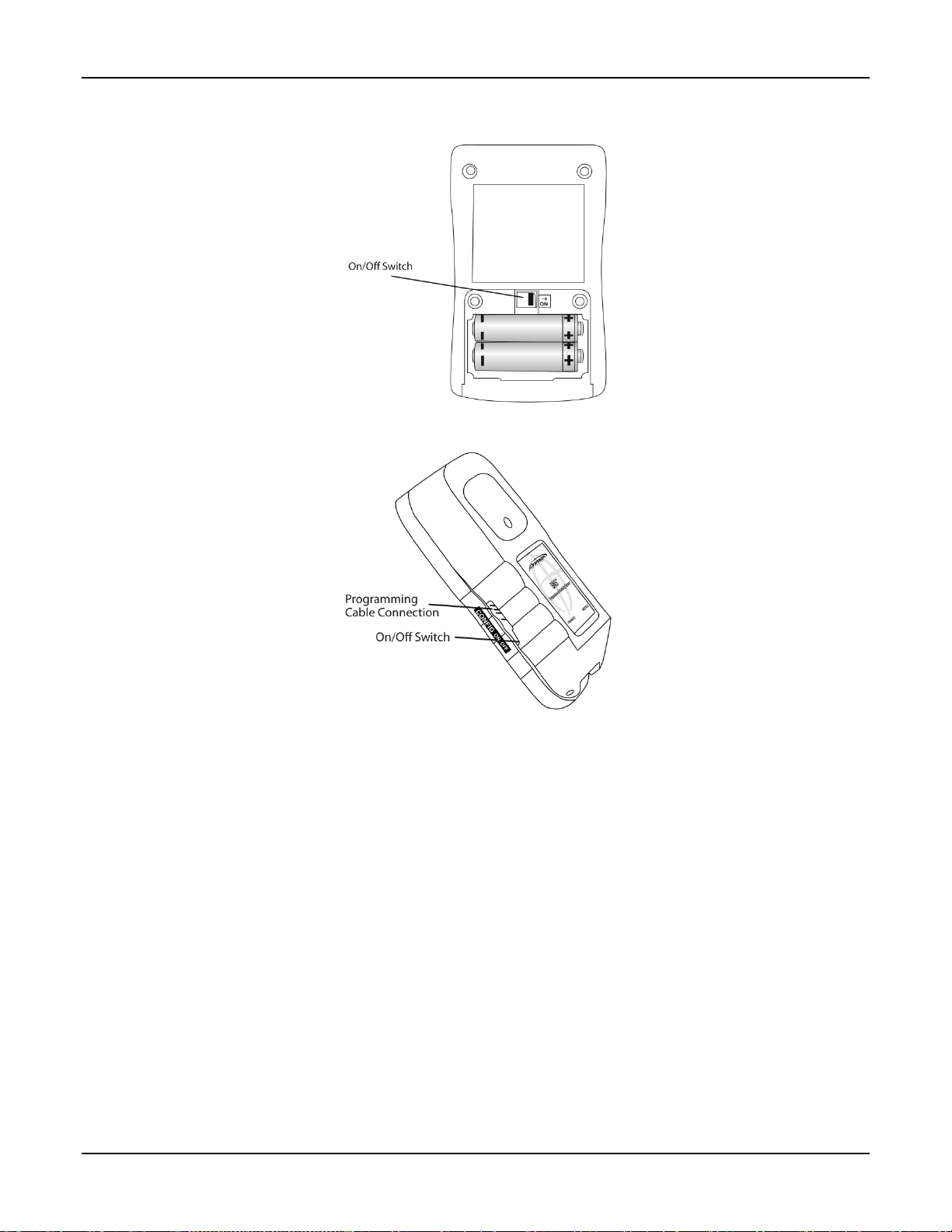
Figure 5: On/Off Switch Model SNS2TPS-2
Figure 6: Side of Model SNS2THS-2
Batteries
SNS battery-powered sensors use two AA batteries located inside the sensor (Model SNS2TNS-2,
Figure 4; Model SNS2TPH-2, Figure 12) or in an externally accessible battery compartment (Model
SNS2TPS-2, Figure 5).
Programming Cable Connection
Battery-powered sensor devices come with a USB programming cable for use when configuring the
sensor device. The standard USB connector connects to the computer that is running the
configuration software utility. The other end of the programming cable connects to the sensor
device’s programming connection. For information on configuring sensors, see Configure Sensors
for the Network on page 25.
As shown in Figure 4, Figure 6, and Figure 7, the location of the programming cable connection
depends on the sensor model.
Features of SNS Battery-powered Sensor Devices Probe Connections
Primex Wireless, Inc. SNS™ Temperature and Humidity Sensors Installation Guide 20
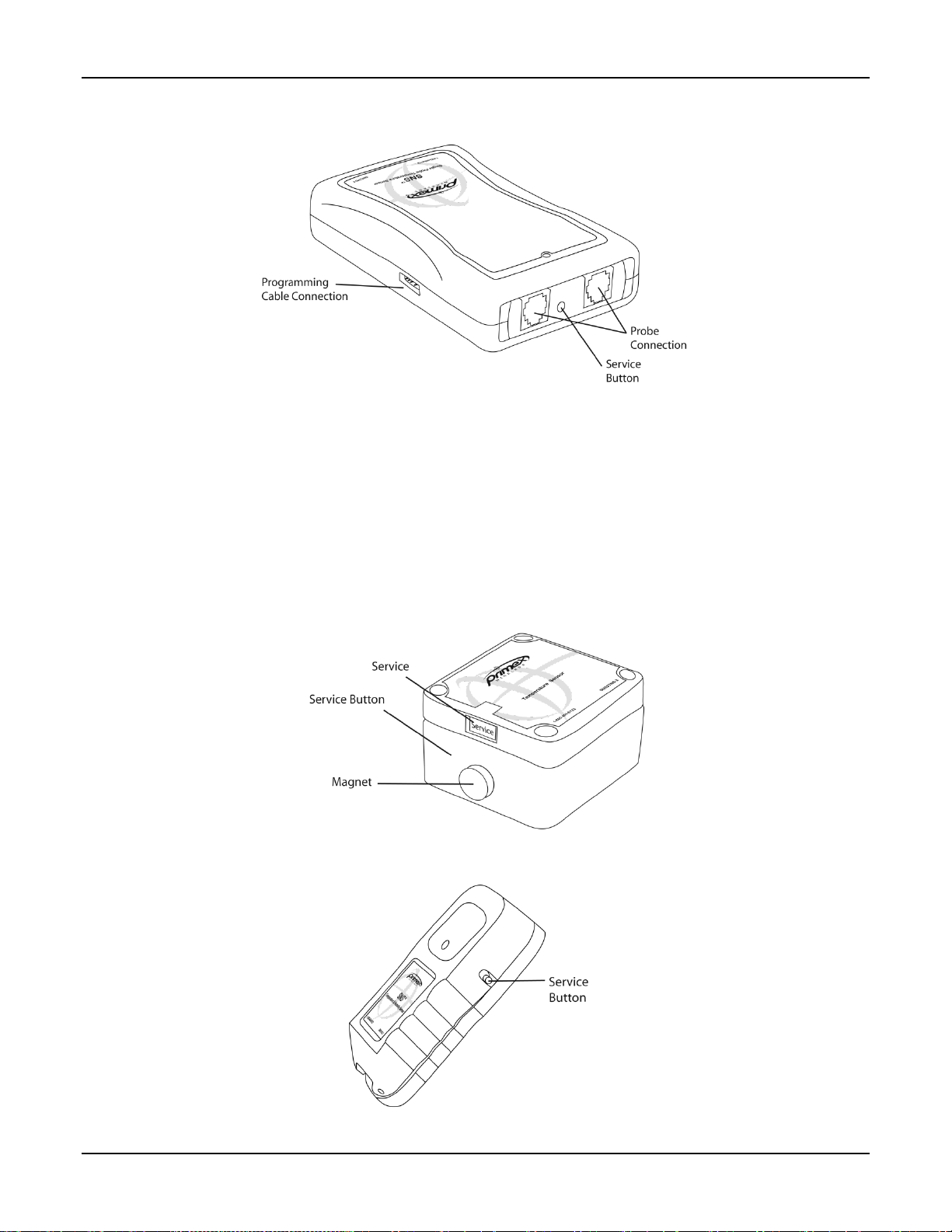
Figure 7: Connections and Service Button on Model SNS2TPS-2
Probe Connections
Single and dual external probe sensor devices contain probe jacks on the end of the sensor device,
as shown in Figure 7.
Service Button
The service button is located on the side or end of the sensor device, depending on the model (See
Figure 7 and Figure 9). As shown in Figure 8, on model SNS2TNS-2, the service button is inside
the sensor device. On this model, the service button is activated by swiping the outside of the
sensor device with the supplied magnet.
Figure 8: Service Button on Model SNS2TNS-2
Figure 9: Service Button on Model SNS2THS-2
This manual suits for next models
12
Table of contents
Other Primex Wireless Accessories manuals


