www.ti.com
2SBOU181–October 2016
Submit Documentation Feedback
Copyright © 2016, Texas Instruments Incorporated
OPT3006EVM User's Guide
1 Hardware Included With Kit ................................................................................................ 3
2 Hardware Setup.............................................................................................................. 5
3 OPT3006EVM Block Diagram ............................................................................................. 6
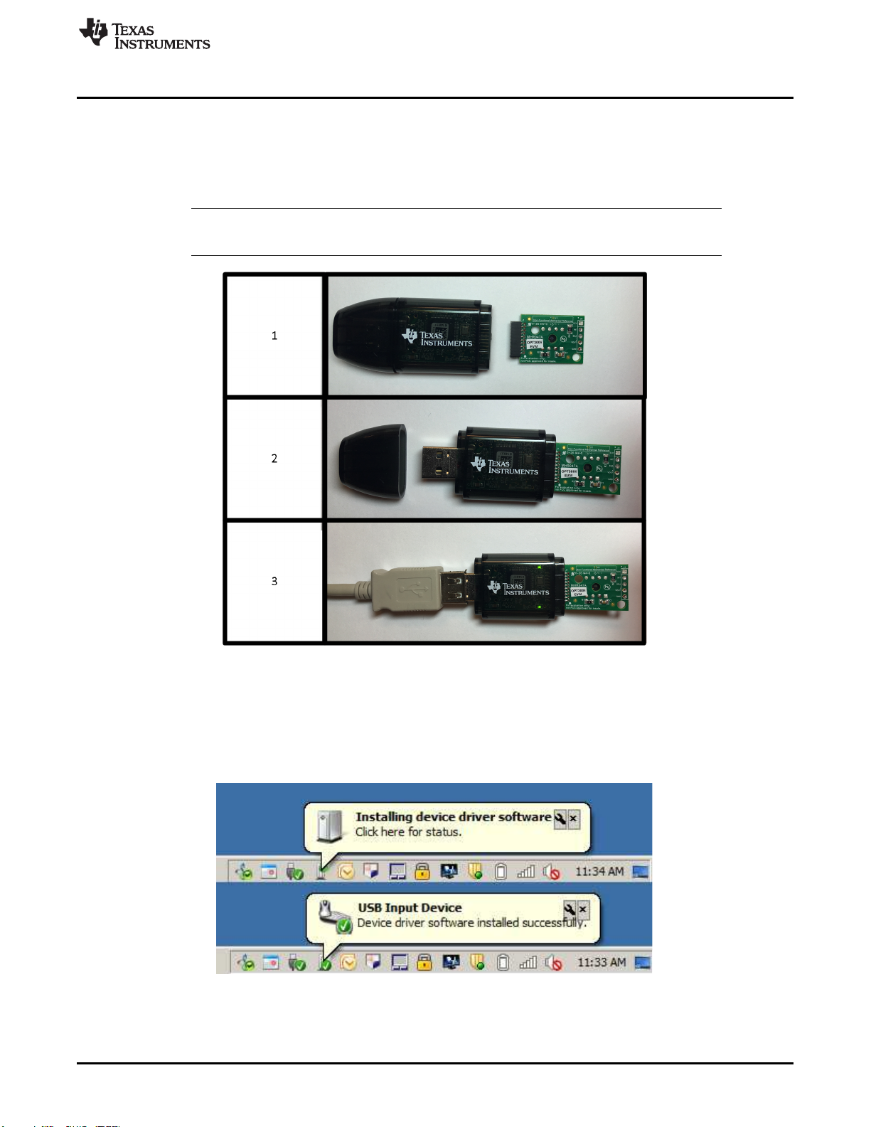
4 Typical Hardware Connection.............................................................................................. 7
5 Typical Response After Connecting OPT3006EVM to Computer..................................................... 7
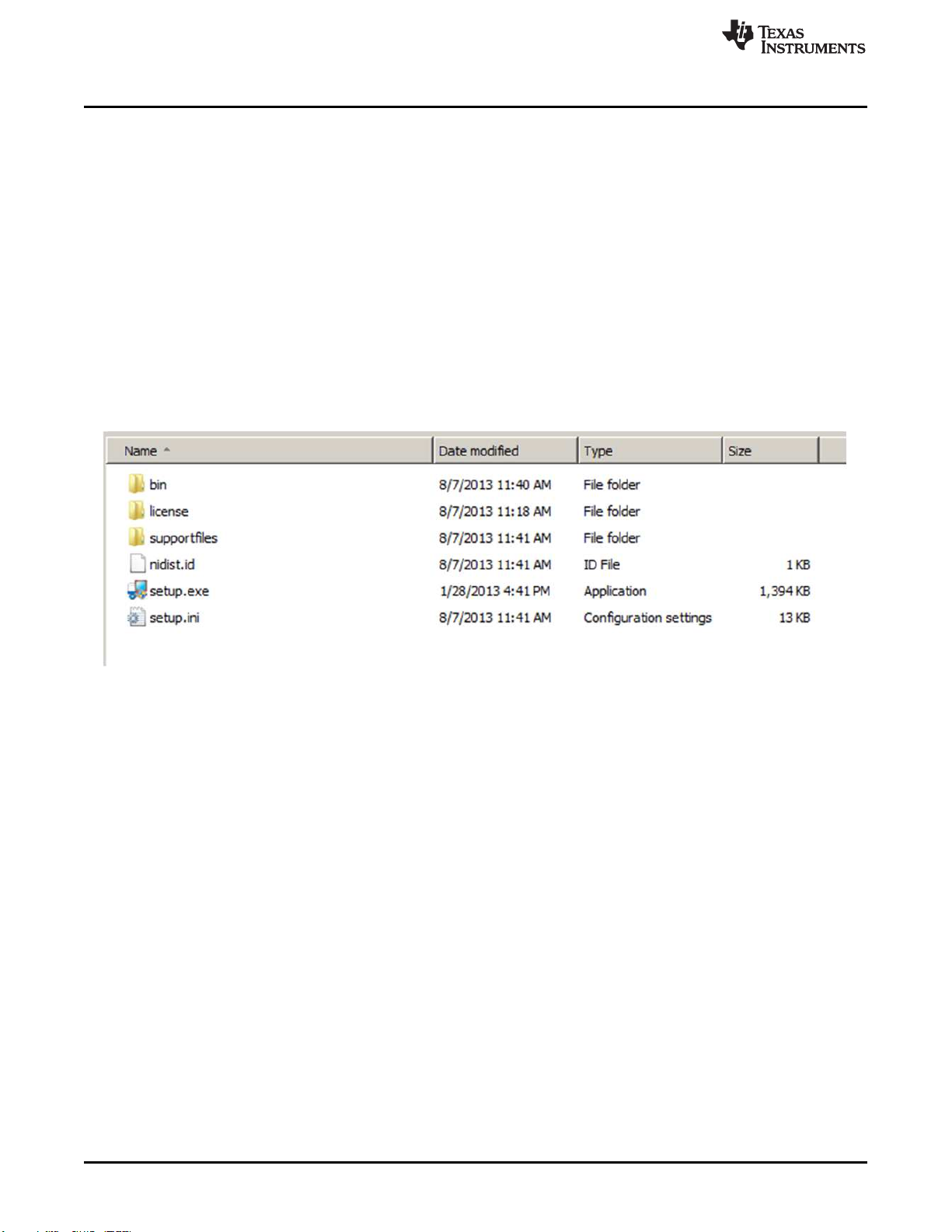
6 Software-Installation Files .................................................................................................. 8
7 Software-Installation Launch............................................................................................... 9
8 Software-Installation Prompts.............................................................................................. 9
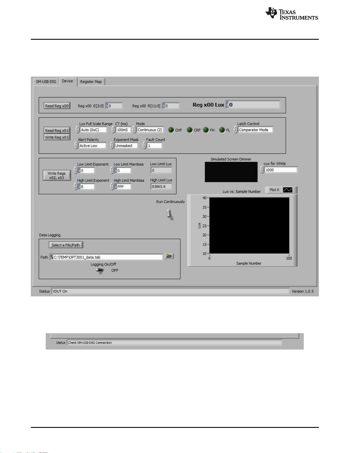
9 Main Operation Screen.................................................................................................... 10
10 Hardware Error Message ................................................................................................. 10
11 Power Indicators............................................................................................................ 11
12 I2C Address Selection...................................................................................................... 11
13 Register x00 Button and Recorded Values............................................................................. 12
14 Register x01 Control and Status Register Bits......................................................................... 12
15 Registers x02 and x03 Lux Limit Controls .............................................................................. 12
16 Simulated Screen Backlight Dimmer .................................................................................... 12
17 Lux vs Sample Number Plot.............................................................................................. 13
18 Re-Initialize Button......................................................................................................... 13
19 Data Logging Setup and Enable ......................................................................................... 14
20 Read All Button on the Register Map Tab with Example Output .................................................... 14
21 OPT3006EVM Schematic, Including MHR046 FPCB................................................................. 15
22 FPCB MHRS046 Schematic, Containing the OPT3006 .............................................................. 16
23 PCB Top-Layer Assembly Drawing...................................................................................... 17
24 PCB Bottom-Layer Assembly Drawing.................................................................................. 17
25 PCB Top Layer ............................................................................................................. 18
26 PCB Bottom Layer ......................................................................................................... 18
27 MHR046 FPCB Top Layer................................................................................................ 19
28 MHR046 FPCB Bottom Layer ............................................................................................ 19
29 MHR046 FPCB Assembly Drawing...................................................................................... 19
List of Tables
1 OPT3006EVM Kit Contents ................................................................................................ 3
2 Related Documentation..................................................................................................... 4
3 OPT3006EVM BOM ....................................................................................................... 20
4 MHR046 FPCB BOM ..................................................................................................... 20