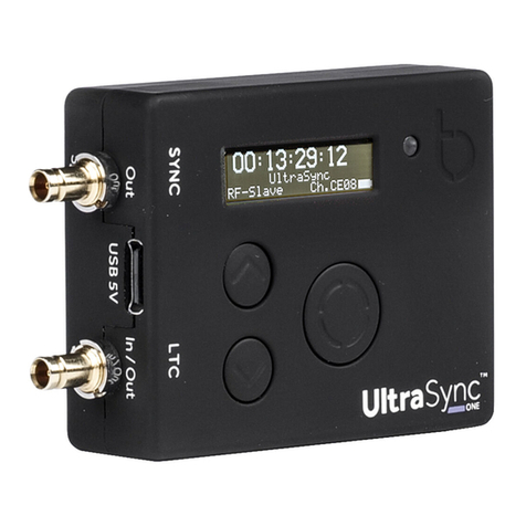
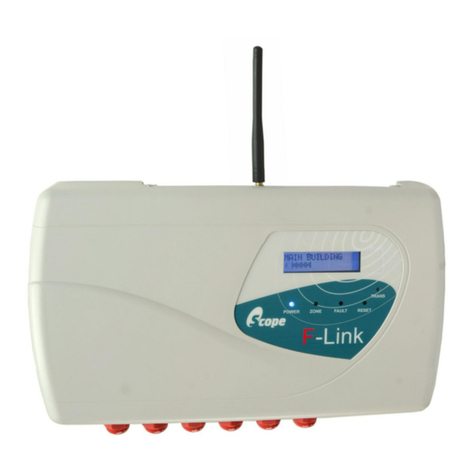
Primex OneVue TX400 User manual

DRAFT
©2019 Primex. All Rights Reserved. The Primex logo is a registered trademark of Primex. All other trademarks are the property of their respective owners. 4/3/2019. Primex, Inc. |
965 Wells Street | Lake Geneva, WI 53147 | www.primexinc.com | Ph: 1-262-729-4853
OneVue 1 Watt Transceiver with External Antenna
Install Guide
Primex ClassicSync

DRAFT
Legal Notice
Copyright ©2019 Primex, Inc. All rights reserved.
Printed in the USA.
Information in this document is subject to change without notice. Software described in this document is furnished under a license
agreement or nondisclosure agreement. The software may be used or copied only in accordance with the terms of those
agreements.
No part of this publication may be reproduced, stored in a retrieval system, or transmitted in any form or by any means, electronic,
mechanical or otherwise, for any purpose, without the prior written permission of Primex, Inc.
Primex, Inc.
Primex is a leading provider of synchronized time and environmental monitoring solutions. Our solutions automate and maintain
facility compliance, increase efficiencies, enhance safety and reduce risk for organizations in the healthcare, education,
manufacturing and government vertical markets.
Worldwide Headquarters
965 Wells Street, Lake Geneva, WI 53147
Phone: 1-262-729-4853 | email: info@primexinc.com | www.primexinc.com
2OneVue 1 Watt Transceiver with External Antenna Install Guide

DRAFT
Regulatory Compliance
Federal Communications Commission (FCC) / Industry Canada (IC)
Primex OneVue Transceiver TX400
License Requirements
lOperation of the Transceiver requires a FCC/IC operating license, which must be obtained prior to operation.
lFCC licenses must be renewed every 10 years and the IC licenses must be renewed annually.
lAs a service, Primex will file the license application if the end-user desires it. An end-user that does not want Primex to file for
the original site license will be required to complete a waiver form, file the required application, and receive a valid license from
the FCC/IC prior to use.If you have any questions or need any assistance, please contact Primex Technical Support.
lPrimex requires a copy of the licenses in order to complete the factory presets.
Product Compliance
lThis device complies with Part 90 and Part 15 of the FCC rules and RSS-119 of Industry Canada.
lOperation of this device is subject to the following two conditions:
1. This device may not cause harmful interference.
2. This device must accept any interference, including interference that may cause undesired operation.
Changes or modifications to any part of the Primex System components not expressly approved by Primex could void the userʼs
FCC/IC authority to operate the equipment.
Radio Frequency (RF)Exposure
To comply with FCC/IC RF exposure requirements for mobile transmitting devices, the Transceiver is only to be used or installed in
locations where there are at least 35 cm separation distance between the antenna of the Transceiver and all persons.
To comply with FCC OET65 and Industry Canada RF exposure requirements, the antenna is only to be used or installed in locations
where the following antenna separation guidelines exist when the Transceiver is in operation. Distance above roofline is for direct
line of sight only. Distance Above Roofline: 8.95 ft. (2.72 m).
Distance above roofline illustration
3

DRAFT
Radio Standards Specification (RSS)
This device complies with Industry Canada licence-exempt RSSs.
Operation is subject to the following two conditions: (1) This device may not cause interference, and (2) This device must accept
any interference, including interference that may cause undesired operation of the device.
Le présent appareil est conforme aux CNR d'Industrie Canada applicables aux appareils radio exempts de licence. L'exploitation est
autorisée aux deux conditions suivantes:
(1) l'appareil ne doit pas produire de brouillage,et
(2) l'utilisateur de l'appareil doit accepter tout brouillage radioélectrique subi, même si le brouillage est susceptible d'en
compromettre le fonctionnement.
The device meets the exemption from the routine evaluation limits in section 2.5 of RSS 102 and compliance with RSS-102 RF
exposure, users can obtain Canadian information on RF exposure and compliance.
Le dispositif rencontre l'exemption des limites courantes d'évaluation de routine dans la section 2.5 de RSS 102 et la conformité à
l'exposition de RSS-102 RF. Les utilisateurs peuvent obtenir l'information canadienne sur l'exposition à la RF et la conformité avec
celle-ci.
This equipment should be installed and operated with a minimum distance of 35 centimeters between the radiator and your body.
Cet équipement devrait être installé et utilisé avec une distance minimum de 35 centimètres entre le radiateur et votre corps.
4OneVue 1 Watt Transceiver with External Antenna Install Guide

DRAFT
Important Safety Instructions
READ ALL INSTRUCTIONS BEFORE INSTALLATION, OPERATION, OR MAINTENANCE OF PRODUCT.
Safety Instructions
Some of the following information may not apply to your particular product model; however, as with any electronic product,
precautions should be observed during installation, operation, and maintenance.
lNever operate the Transceiver without the antenna being properly connected to the Transceiver.Operating the Transceiver
without an antenna can lead to permanent damage of the Transceiver and poses a safety risk.
lDo not touch any of the antennas while broadcasting.
lStandard acceptance procedures must be followed prior to operating this equipment in the proximity of life support systems.
lDo not operate the Transceiver outdoors, in wet areas where there is standing water, or in areas where there is condensation or
the risk of condensation. Use in any of these environments will damage the Transceiver and void the warranty.
lDo not open the Transceiver to alter the internal elements in any way. This will void the warranty and could lead to unsafe
conditions, malfunction, and violations of FCC/IC regulations.
lDo not use a metal ladder during installation of the external antenna.
lDuring antenna installation, be sure to wear shoes with rubber soles and heals and wear protective clothing with long sleeves
and rubber gloves.
lDo not install the antenna on a wet or windy day when lighting or thunder is in the area or near power lines. Power lines,
telephone lines, and guy wires look the same. As a precaution please assume any wire can electrocute you.
The installation, maintenance, or removal of an antenna requires qualified, experienced personnel. The installation instructions are
written for such installation personnel.
Antenna systems should be inspected once a year by qualified personnel to verify proper installation, maintenance, and condition
of equipment.
Primex disclaims any liability or responsibility for the results of improper or unsafe installation practices.
5

DRAFT
Contents
Overview of the Primex ClassicSync Solution 8
Architecture 8
Time synchronization 8
Transceiver power-up sequence 8
Transceiver power failure 9
Specifications 10
Specifications: OneVue 1 Watt Transceiver 10
Specifications: GPS Receiver 12
Specifications: Ground plane omnidirectional antenna 13
Install OneVue Transceiver with External Antenna 14
Before you begin 14
Required tools and equipment 14
Install location requirements 14
Step 1: Assemble ground plane omnidirectional antenna 15
Step 2: Assemble antenna mast 15
Step 3: Secure antenna to mast 16
Step 4: Route antenna LMR 400 coaxial cable 16
Step 5: Mount antenna mast 16
Step 6: Ground antenna mast 21
Step 7: Install GPS Receiver 21
Step 8: Weatherproof and secure antenna cabling 23
Step 9: Ground Transceiver 23
Step 10: Establish Transceiver connections and apply power 24
Step 11: Configure Transceiver settings 24
Step 12: Verify Transceiver is operational 27

DRAFT
Overview of the Primex ClassicSync Solution
Learn how the solution works and how the system devices provide synchronized time.
Architecture
The Primex ClassicSync solution provides synchronized time using our 72-73 MHz unique broadcast frequency to transmit a
wireless signal to all system devices. The frequency allows the system wireless signal to broadcast through common building
materials and across longer distances with less potential for signal interference. The solution can be configured with either a GPS or
NTP time source. The system consists of a single Transceiver with an internal or external antenna, a GPS Receiver (optional),
Repeater Transceiver (optional), and the system clocks and other devices in a single building, to a campus wide deployment.
Time synchronization
Once a Transceiver has received its time, from either a GPS Receiver or NTP time source or another Transceiver, it sets its internal
clock. It then transmits time information over the 72-73 MHz wireless radio frequency signal to the secondary system devices. As a
result, the system devices are precisely synchronized to each other and all time and events are kept current.
Time Source: Transceiver receives time from a GPS Receiver or a NTP server and then broadcasts received time and event schedules
to clocks and other system devices. The Global Positioning System (GPS) Receiver draws time information from the U.S. Government
Satellites. The GPS Receiver then sends the time to the Transceiver.
Frequency and channel: Transceiver operates on channels with 20kHz bandwidths and 72-73 MHz frequency and is preset to one of
the channels licensed by the FCC/IC to minimize interference on these frequencies and channels.
By factory default, a Transceiver with an external antenna: transmits (broadcasts) its synchronized time to the system clocks and
devices from the 39th to the 6th minute of the next hour and changes to a standby mode during the 7th to the 38th minute of the
hour (standard broadcast schedule). Transceiver also has a power-on transmit schedule that sets the duration of time the
Transceiver transmits (broadcasts) a signal when first powered on (factory default 8 hours).
Analog Clock signal search frequency: six pre-scheduled times a day at 10:01, 2:01 and 6:01 a.m. and p.m. lock time (not the actual
time of the day), a clock's receiver turns on to search for a Transceiver signal to receive a time update, starting with the previously
stored channel number.
Digital Clock/Timer signal search frequency: every 10 minutes on the 5's (5, 15, 25, 35, 45, 55 minutes) of the hour, a clock's receiver
turns on to search for a Transceiver signal to receive a time update.
Transceiver power-up sequence
1. When power is first applied, it searches for a time source. It first searches for GPS and then NTP.
2. If a time source is not found, it uses its onboard real time clock (RTC) and continues to search for its time source.
3. If a time source is not found, the Transceiver is set to a warning state with a time sync failure status, its front panel Caution LED
status indicator is illuminated, and transmits its state to OneVue at its scheduled check-in time (default every 5 minutes).
4. If it fails to get time from either source consecutively for 30 minutes (default), it enters an alarm state, its front panel Error LED
status indicator is illuminated, and transmits its state to OneVue at its scheduled check-in.
8

DRAFT
5. If the RTC clock is off significantly, the Transceiver it enters a critical error state, its front panel LED Error status indicator is
illuminated, and transmits its state to OneVue at its scheduled check-in. Only occurs after the first 30 minutes of operation if the
RTC continues to be significantly off.
Transceiver power failure
During a power failure, the Transceiver continues to track time with the last valid time signal that it received. Once the power had
been restored, the Transceiver begins to broadcast (even without a valid time signal) to the down-stream components. Once the
Transceiver has been powered on for a few hours, it's capable of keeping track of time off its internal backup power for up to eight
hours.
lThe system has a fail-safe design. If the failure of a system component or power loss to a component occurs, all down-stream
components continue normal operations using their own internal time base.
lIf after a specified period of time communication has not been restored, a visual indicator on its front panel is illuminated and its
state is sent to OneVue during its next scheduled check-in. It remains in this state until communication is restored.
NOTE
In the event power to a Transceiver is shut off and turned back on (power cycled) the Transceiver will broadcast
continuously based on its Power-on Transmit schedule (default 8 hours). Power cycling the Transceiver can be used to
set/reset system devices. It's not recommended to power-cycle a Transceiver when in an error state, as indicated when its
front panel Error LED indicator is illuminated.
9OneVue 1 Watt Transceiver with External Antenna Install Guide

DRAFT
Specifications
Primex OneVue Transmitters use a 72-73 MHz broadcast frequency to transmit a wireless radio frequency to seamlessly synchronize
every clock and independently to display the exact same time. Leveraging the precision of GPS satellite or Network Time Protocol
(NTP) time, the Transmitters wirelessly synchronize time with Primex 72-73 MHz analog and digital clocks, timers and other
receivers throughout a facility.
Specifications: OneVue 1 Watt Transceiver
Parameter Specification
Operating
Frequency
Range
72-73 MHz
Channels 49 channels available
Channel
Bandwidth
20KHz
Dimensions 17 in. L x 12 in. W x 1.7 in. D (43.2 cm x 30.5 cm 4.32 cm)
Maximum
Transmission
1 Watt (at Transceiver)
Radio
Technology
Narrowband FM
Weight 9 lb.
Power Supply Input: 120 VAC, 50/60 Hz, 0.6 Amp
Output: 9 VDC, 2.78 Amp
3 ft. (0.9 m) cord
Bluetooth
Technology
Bluetooth®low energy (v5) wireless technology. To allow pairing with OneVue Device Configurator app for
configuration and setting management.
User-defined
settings
(OneVue
Device
Configurator
app)
Time Zone, Daylight Saving Time with bypass option, up to three NTP time sources, Power-on Transmit
Schedule, Normal Transmit Schedule, Firmware, Transmit Channel, and Repeater Channel.
10 OneVue 1 Watt Transceiver with External Antenna Install Guide

DRAFT
Parameter Specification
User-defined
settings
(OneVue Sync
software)
Legacy Clock Time Zone, Alarm Delay, Firmware, Unresponsive Timeout, and Check-in Interval.
Front Panel Four LED status indicators (Power, Transmit, Caution, Error) and Bluetooth labeled push-button to pair
Transceiver with the Primex OneVue Device Configurator (ODC) app.
Rear Panel Network LAN port (RJ-45 Ethernet, 100/10 Mbps, 802.3 Ethernet), GPS In port (MiniDIN 7-Pin), External Antenna
connector (coaxial, n-male), Baseboard Monitor port (MiniDIN 9-Pin, for use with 5 or 30 Watt Transceiver only),
dry contact closure relay panel (for use with specified Primex products), and pin port to allow end-user
connection initiation (check-in) to the Primex OneVue cloud-based software.
Top Panel Internal Antenna connection.
Operating
Range
32° to 122° F (0° to 50° C), non-condensing environment
NOTE
Canadian Notice: 5 or 30 Watt Transceiver with an external antenna: The manufacturer rated output power of this
equipment is for single carrier operation. For situations when multiple carrier signals are present, the rating would have to
be reduced by 3.5 dB, especially where the output signal is re-radiated and can cause interference to adjacent band users.
This power reduction is to be by means of input power or gain reduction and not by an attenuator at the output of the
device.
11

DRAFT
Specifications: GPS Receiver
A GPS Receiver draws time information from the U.S. Government Satellites, providing the system with Coordinated Universal Time
(UTC).
lMounted to rooftop, pole, or window (not a Low-E glass window).
lGPS Receiver sends UTC time to the Transceiver via the NMEA 0183 standard protocol.
lOptional GPS extension cable. A specially designed low-resistance cable to extend the distance between GPS Receiver and
Transceiver. The maximum total length of the cable cannot exceed 200 ft. (60.96 m).
Parameter Specification
Cable 10 ft. (3.05 m) cable
50, 100 and 200 ft. (15.24 m, 30.48 m and 60.69 m) extensions available. The maximum total length of the cable
cannot exceed 200 ft. (60.96 m).
Dimensions 2.5 in. W x .75 in. H (6.35 cm x 1.91 cm)
Mounting
Bracket
3.5 in. W x 1.4 in. H x 4.5 in. D (8.89 cm x 3.56 cm x 11.43 cm)
Included for rooftop or window installation.
Weight 0.75 lb. (.34 kg)
Operating
Range
-32° to 158° F (-30° to 70° C)
12 OneVue 1 Watt Transceiver with External Antenna Install Guide

DRAFT
Specifications: Ground plane omnidirectional antenna
A Primex Transceiver's external antenna is a heavy duty, light weight ground plane antenna designed to be mounted outdoors.
lDesigned for mounting to a 1.25 in. (3.17 cm) rigged galvanized conduit.
lBest operation is obtained when the ground plane rods are above all objects.
Parameter Specification
Frequency Range 68–80 MHz
Gain 0 dBd
Impedance 50 ohms
VSWR <1.5:1
Polarization Vertical
Maximum Input Power 75 Watts (at 50° C)
H-plane Beamwidth Omni
E-plane Beamwidth 78 degrees (half-power)
Connector N-female
Weight 4.4 lb. (2 kg)
Dimensions Radiating element: 29.4 in. H (74.7 cm). Ground radials: 41.5 in. W (105.41 cm)
Lighting Protection Direct Ground
Wind Survival Rating* 120 mph (200 kph)
Compliance FCC Part 90 Accepted. IC RSS-119 Accepted
NOTE
* Mechanical design is based on environmental conditions as stipulated in EIA-222-F (June 1996) and/or ETS 300 019-1-4
which include the static mechanical load imposed on an antenna by wind at maximum velocity.
13

DRAFT
Install OneVue Transceiver with External Antenna
Leveraging the precision of GPS satellite or Network Time Protocol (NTP) time, OneVue Transmitters wirelessly synchronize time for
analog and digital clocks, timers and other Repeater Transmitters throughout a facility.
Before you begin
lReview the Installation Guidelines and identify the installation location of the Transceiver and system components.
lInspect system components to verify packaging includes all supplied parts for each system component and verify no damage
has occurred during shipping.
lDo not install or attempt to set the system wireless clocks or devices until the Transceiver and its components are installed and
configured. Transceiver is powered, its time source is configured and time has been received, and is fully operational.
Required tools and equipment
To following tools and equipment below are required to install a Transceiver with an external antenna.
lHammer drill
lPower drill
l3/4 inch concrete drill bit, 18 in. (45.7 cm) long
lPenetrating mount only: 5/8 inch concrete drill bit, 18 inch (45.7 cm) long
l1/2 inch wrench
l3/4 feet deep well socket with ratchet
l10 inch (25.4 cm) adjustable wrench
lPhillips screwdriver
lFlat head screwdriver
lLineman’s pliers
lShears/scissors
lSilicone caulk; required to seal cabling/ground penetration
lTransceiver rack (recommended)
lBuilding ground near Transceiver
lGround near transmitting antenna
Install location requirements
When planning the system installation of a Transceiver with an External Antenna, Primex recommends taking into consideration the
below guidelines. Location is extremely important to ensure the best operation of your system.
lTransceiver should be located on the tallest building near center of area of coverage. In a multi-story building, locate Transceiver
on the top floor; significantly improves coverage to the lower floors due to the “umbrella” pattern of transmission.
lTransceiver must be located within 100 ft. (30.4 m) from the antenna. The maximum cable length allowed between the external
antenna and Transceiver is 100 ft. (30.4 m). The system is attenuated to the 100 ft. (30.4 m) of coaxial cable; typically figure
between 80 to 85 ft. of usable cable length.
lTransceiver must be located a minimum of 4 ft. (1.2 m) above the floor.
lTransceiver must be located within 3 ft. (0.9 m) from a 120 VAC electrical outlet. 10 AMP dedicated service recommended.
lTransceiver must be located in a controlled environment that is 32 to 122° F (0 to 50° C) and non-condensing humidity
environment.
lExternal antenna must be located at a minimum of 15 ft. (4.5 m) clear from the radius of other antennas.
14 OneVue 1 Watt Transceiver with External Antenna Install Guide

DRAFT
lExternal antenna must be located at least 10 ft. (3 m) from normal traffic area.
lExternal antenna mast must be located within 10 ft. (3 m) from earth ground.
lExternal antenna cannot be placed on or directly adjacent to walls or metal structures.
lExternal antenna cannot be located near television receiving antennas.
lExternal antenna cannot be mounted indoors or in enclosed areas.
lExternal antenna cannot be mounted to pre-existing antenna towers. If this is desired, contact Primex prior to installation.
Step 1: Assemble ground plane omnidirectional antenna
1. After removing the antenna from the shipping box, inspect all contents to ensure all parts are on hand and no damaged has
occurred during shipping.
2. Screw the three radials into the base of the antenna.
3. Assemble the U-bolt on the base of the antenna. The Mast is to be aligned with the top of the mast channel.
Step 2: Assemble antenna mast
The Antenna Mast has two sections secured by a hex bolt during shipment. The two sections include a5 ft. x 1.25 in. (1.52 m x 2.54
cm) rigid galvanized conduit and a 5 ft. x 1 in. (1.52 m x 3.17 cm) rigid galvanized conduit.
NOTE
1 Watt Transceiver with external antenna only: Non-penetrating mounting kit only includes the 5 ft. x 1.25 inch rigid
galvanized conduit section.
1. Loosen and remove the hex bolt.
2. Remove the 5 ft. x 1 in. (1.52 m x 3.17 cm) rigid galvanized conduit section.
3. Insert the 5 ft. x 1 in. (1.52 m x 3.17 cm) rigid galvanized conduit section into the 5 ft. x 1.25 in. (1.52 m x 2.54 cm) rigid
galvanized conduit section in reverse as shipped - to attain a combined antenna mast length of 9 ft. (2.74 m).
4. Align the sections fastening holes and secure sections together using the supplied hex bolt and nuts.
15

DRAFT
Step 3: Secure antenna to mast
1. Attach and fasten the antenna channel side base to the top of the 1 inch rigid galvanized conduit section.
2. Use a 1/2 inch wrench to tighten the nuts on both of the U-bolts, both evenly and securely. To ensure it's secure, tighten the
second nut to the first nut.
Step 4: Route antenna LMR 400 coaxial cable
1. Drill a 1 in. (2.54 cm) hole through an exterior wall of the building that is in close proximity to the antenna installation location.
2. Roll out the LMR 400 cable to prevent kinks from developing during routing.
3. Route the LMR 400 cable female connector from the Transceiver installation area to the outside installation location of the
antenna, leaving enough cable for two 1 ft. (0.30 m) diameter coils at the base of the antenna mast.
4. Form and secure two 1 ft. diameter (305 mm) loops in the LMR 400 cable at the base of the mast for lightning protection.
5. Connect the LMR 400 cable to the antenna.
Step 5: Mount antenna mast
There are three available mounting methods. Installation is dependent upon the mounting kit supplied with the system.
NOTE
Mounting the antenna mast may require two people.
Non-penetrating roof mount kit
The Non-Penetrating Antenna Kit is designed for mounting a ground plane omnidirectional antenna when mounting to the side of
a structure is not practical. The overall footprint of the frame is 29 inches x 35 ½ inches (73.66 cm x 88.9 cm).
NOTE
Installation requires six 8 in. x 8 in. x 16 in. concrete blocks (not supplied).
The kit is supplied with the following parts. If any of these items are missing, please contact Primex.
Description Qty
Rigid galvanized conduit mast | 5 ft. x 1.25 inches (1.52 m x 3.17 cm) 1
Tripod leg: 27 in. (2.54 cm) each in length 3
Frame rail (long):34 ¾ in. (88.26 cm) 2
16 OneVue 1 Watt Transceiver with External Antenna Install Guide

DRAFT
Description Qty
Frame rail (short): 28 ¼ in. (71.75 cm) 4
Grounding Clamp 1
Long carriage bolt 1
Short carriage bolt 11
Flat washers 12
Lock nuts 12
Assemble non-penetrating antenna roof mount
1. Verify the kit contents.
2. Assemble the outer frame by laying the two long frame rails parallel to each - approximately 30 in. (76.2 cm) apart.
3. Insert a short carriage bolt from the bottom at each frame rail end, pointing skyward (4 total).
4. Connect the two long frames rails by placing the two short frame rails on top of the four protruding bolts to form a rectangle.
Make sure the square holes in the short tail "sides" are directly opposite each other.
5. Place a washer and nut on each of the four bolts and finger tighten.
6. Position the tripod within the four-sided frame.
7. Secure the three tripod legs to the inside of the frame by inserting three short bolts, from the inside and placing the washer and
nut on the outside of the frame.
8. Drop the bottom of the mast (end with hole) through the top of the tripod collar.
9. Place the remaining two short rails parallel to each other, separated by the bottom of the mast.
10. Align the hole at the bottom of the mast, with the two square holes in the short frame rail sides.
11. Insert the long bolt and connect the frame rails to the mast.
12. From the underside of the frame, insert the four remaining short bolts upward and connect the inner short tails to the frame.
13. Tighten all nuts to secure.
14. Use six 8 in. x 8 in. x 16 in. concrete blocks to ballast the antenna mounting. Blocks are to be placed from rail to rail on each side
of the mast; three blocks per side with a single block placed on each end and one in the middle.
17

DRAFT
Penetrating antenna kit
The penetrating antenna kit contains the materials required to mount the antenna to a wooden pole or masonry wall. A 5/8 in. (1.58
cm) diameter mounting hole is required and the maximum diameter of the pole or wall thickness is 14 in. (35.56 cm).
The kit is supplied with the following parts. If any items are missing, contact Primex.
Description Qty
Rigid galvanized conduit section: 5 ft. x 1.25 in. 1
Rigid galvanized conduit insert: 5 ft. x 1 in. 1
Antenna mounting clamp 2
Hex head bolt: 1/2 in. 2
Bolt washer: 1/2 in. 8
Lock washer: 1/2 in. 8
Hex nut: 1/2 in. 8
Mount antenna with penetrating antenna kit
NOTE
The recommended diameter of the pole or the wall thickness should not exceed 14 in. (35.56 cm).
1. Verify the kit contents.
2. Assemble both clamps, as shown below, tightening the hex nuts to a torque of approximately 45 ft-lbs.
18 OneVue 1 Watt Transceiver with External Antenna Install Guide

DRAFT
3. Remove the nut and washer from the 14 inch threaded rod.
4. Drill a 5/8 in. hole through the top of an exterior wall.
5. Insert the 14 in. threaded rod through the hole in the wall. If the thickness of the wall is greater than 10 in. a longer rod may be
required. Different lengths of rod are available at hardware stores. If a longer threaded rod is needed, use a 5/8”-11 threads per
inch rod.
6. Place the nut and metal plate over the rod.
7. Tighten the square nuts to an approximate torque of approximately 55 ft-lbs.
8. Drill a second 5/8 in. (1.59 cm) hole 2.5 ft. (0.76 m) directly below the first hole.
9. Ensure both clamps are vertically aligned, as shown below
10. Repeat Steps 4 through 6.
11. Connect the LMR 400 cable to the antenna. Be sure the connection is tight.
12. Insert the mast into the clamps.
13. Tighten both clamps evenly and securely.
14. Install Gelwrap splice enclosure over the connection between the LMR400 cable and antenna. Secure Gelwrap to mast using
common electrical tape or cable ties.
15. Next, route the antenna cable.
Pole mount kit
The antenna pole mount kit is designed for the purpose of mounting the antenna to round or angled tower legs.
lThe clamps can be used on round tower legs that measure from 1.25 in. to 3.25 in. (3.17 cm to 8.25 cm) OD or on angled tower
legs that measure up to 3 in. (7.62 cm) on a side.
lThe center section of each clamp is welded to provide mechanical stability and all parts are hot-depped galvanized steel.
19

DRAFT
The kit is supplied with the following parts. If any of these items are missing, please contact Primex.
Description Qty
Rigid galvanized conduit section: 5 ft. x 1.25 in. 1
Rigid galvanized conduit section: 5 ft. x 1 in. 1
X style clamp 2
U-clamp 4
1/2 inch all thread bolt 4
1/2 inch lock washer 16
1/2 inch hex nut 16
Mount antenna using a pole mount antenna kit
1. Verify the kit contents.
2. Assemble both clamps, tightening the hex nuts to an approximate torque of approximately 45 ft-lbs.
3. Tighten half of one clamp two feet below the top of the pole. Use a 3/4 inch wrench to do this and be sure to tighten the
clamps both evenly and securely.
4. Using a 3/4 inch wrench, tighten half of the other clamp a few in. below the top of the pole. Be sure to tighten the clamps both
evenly and securely.
5. Connect the LMR 400 cable to the antenna. Be sure the connection is tight.
6. Insert the mast into the clamps. The bottom of the mast should be a minimum of 2 inches below the bottom clamp.
7. Using a 3/4 inch wrench, tighten all nuts on both clamps.
8. Next, route the antenna cable.
20 OneVue 1 Watt Transceiver with External Antenna Install Guide
Table of contents

