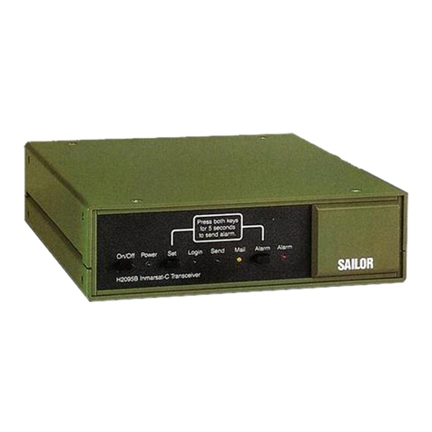
Thrane&Thrane TT-3020B Product manual

TT-3020B
Maritime
Capsat Transceiver
for the
Inmarsat-C Network
Technical Reference Manual
Version 2.20
© Copyright Thrane & Thrane A/S June 1995
Tobaksvejen 23, DK-2860 Soeborg. Denmark

Information in this document is subject to change without notice and does not represent a commitment on the part of Thrane &
Thrane A/S.
© 1995 Thrane & Thrane A/S. All right reserved. Printed in Denmark.
Document Number TT-99-103373-220. Release Date: 19JUN95

Thrane & Thrane
TT-3020B Capsat Transceiver
Technical Reference Manual
19JUN95 Page i
Table of Contents
1. Introduction 1
2. The Maritime facilities 2
2.1 Scanning and Login 2
2.2 Distress 2
2.3 Link Test 2
2.4 Message transmission 3
2.5 EGC message reception 3
3. System Generation 4
3.1 The system generation menu 4
3.2 Entering your mobile number 5
3.3 Initialising system parameters 5
3.3.1 Write protection 6
4. Built-in GPS 8
4.1 Introduction to the GPS System 8
4.1.1 The basic idea - Satellite ranging 8
4.2 The GPS module 10
4.2.1 Feature list 10
4.3 Satellite Navigation 12
4.3.1 Four Satellite Navigation (3D) 12
4.3.2 Three Satellite Navigation (2D) 12
4.3.2.1 Constant Altitude with Unknown Value 13
4.3.2.2 Constant Altitude with Known Value 13
4.3.2.3 Variable Altitude with Known Values 13
4.3.3 Basic Modes of Three SV Navigation 13
4.3.3.1 Auto Hold Mode 13
4.3.3.2 Amended Hold Mode 14
4.3.4 Almanac 14
4.3.5 Error Outputs 14
5. Antenna switch 17
5.1 Introduction 17
5.2 Commands 18
5.2.1 Timer 1 18
5.2.2 Timer 2 18
5.2.3 Nominal Threshold 19
5.2.4 Minimum Threshold 19
5.2.5 Scanning 19
5.2.6 Fixed antenna 20
5.2.7 Remote unit list 20

Thrane & Thrane
TT-3020B Capsat Transceiver
Technical Reference Manual
Page ii 19JUN95
5.3 Status information 21
6. Using a Reader/Puncher in the Capsat system 22
6.1 Introduction 22
6.2 Connections and setup 22
6.3 TT-1610A High speed Reader/Puncher 22
6.4 Receiving and punching messages 24
6.4.1 Setup of reception 24
6.4.2 Punching paper tape messages 25
6.4.3 Punching tapes in binary mode 25
6.5 Reading and transmitting messages 26
6.5.1 Reading paper tape messages 26
6.5.2 Reading tapes in binary mode 27
6.5.3 Transmitting messages 27
7. Transceiver Software Details 28
7.1 EGC Message header format 28
7.2 Provider Name Mapping 30
7.2.1 Introduction 30
7.2.2 Map technique 30
7.3 Baudot Characters 32
7.4 Use of the Transceiver built-in speaker 33
7.5 T-Bus Software Interface Description 35
7.5.1 TT-3042A and TT-3042B Remote Alarm 35
7.5.1.1 Introduction 35
7.5.1.2 Status command 36
7.5.1.3 Print command 37
7.5.1.4 Msg_info command 37
7.5.1.5 Send_nmea command 38
7.5.1.6 Position command 38
7.5.1.7 Time command 39
7.5.2 Antenna Switch 40
7.5.2.1 Introduction 40
7.5.2.2 Status Poll 40
7.5.2.3 Switch Antenna 40
8. Capsat Transceiver Service 41
8.1 Service 41
8.1.1 CPU board: TT 37-102819 41
8.1.2 Power supply: TT 37-102120 43
8.1.3 Demodulator / down converter board: TT 37-102019 44
8.1.4 Built-in GPS Module: TT 88-300421 45
8.1.4.1 Test Summary Word 45
8.2 Replacements 46
8.2.1 How to replace a CPU board: TT 37-102819 46
8.2.2 How to replace an FGU board: TT 37-100522 46
8.2.3 How to replace a demodulator board: TT 37-102019 46
8.2.4 How to replace a power supply: TT 37-102120 47
8.2.5 How to replace an antenna unit: TT 69-102881 47
8.2.6 How to replace the Built-in GPS Module: TT 88-300421 47

Thrane & Thrane
TT-3020B Capsat Transceiver
Technical Reference Manual
19JUN95 Page iii
8.3 The TT-3020B status screen information 48
8.3.1 Hardware information 48
8.3.1.1 Synth's 49
8.3.1.2 LO 1/2 49
8.3.1.3 Corr.A/C/R 49
8.3.1.4 Dif/Temp 49
8.3.1.5 RX/TX/AGC/FIFO 50
8.3.1.6 R/C-B/B/S 50
8.3.2 Software information 51
8.3.2.1 Synchronisation 51
8.3.2.2 Logged in 51
8.3.2.3 TDM type 52
8.3.2.4 TDM channel number 52
8.3.2.5 Current channel 52
8.3.2.6 Current protocol 52
8.3.2.7 TDM origin 53
8.3.2.8 TDM frame number 53
8.3.2.9 BB error rate 53
8.3.2.10 Serial number 53
8.3.2.11 Mobile number 53
8.3.2.12 Preferred ocean 53
8.3.2.13 Activities in queue 53
8.3.3 Printing the information 54
8.3.4 Storing the information in a file for transmission 54
9. Handling of communication-error situations 55
9.1 No synchronisation 55
9.2 Protocol errors 56
9.2.1 List of Link Error Messages 57
9.2.1.1 LES messages in case of a pending or rejected call 57
9.2.1.2 LES messages in case of an aborted call 58
9.2.1.3 Transceiver Messages 58
9.3 Login impossible 61
9.4 Tuning fails 62


Thrane & Thrane
TT-3020B Capsat Transceiver
Technical Reference Manual
19JUN95 Page 1
1. Introduction
This manual explains some of the details of a model TT-3020B Maritime Capsat Transceiver and provides
instructions for using non-standard equipment together with the Transceiver and servicing and testing the
Transceiver.

Thrane & Thrane
TT-3020B Capsat Transceiver
Technical Reference Manual
Page 219JUN95
2. The Maritime facilities
2.1 Scanning and Login
The unique Maritime features are:
Automatic scanning every 24 hours of the preferred ocean region.
Automatic scanning at a BBER of 80.
Automatic scanning when turning on an uncommissioned Transceiver.
The Maritime version scans the preferred ocean (or all oceans) every 24 hours to keep the Transceiver tuned to the
strongest NCS signal as your Transceiver position is changed.
The bulletin board error rate BBER is an indication of the satellite link quality. The Maritime version starts a scan
when this value exceeds 80 (after 80*8.64 seconds = 11.5 minutes).
When turning on the power of an uncommissioned Transceiver the Maritime version will start a scan and then start a
login, if the unit is not logged in.
2.2 Distress
When in the Maritime mode the user can send a distress alert to an LES by means of the Message Handling Program
distress menu, by pressing the TT-3020B Set and Alarm front panel buttons or when using the TT-3042B Remote
Alarm, by pressing the Alarm button here.
2.3 Link Test
A manual distress alert test is possible.
The Maritime Transceiver will ask the user during a Link Test (Performance Verification Test) to manually send a
test distress alert.
If the request is ignored the Transceiver will automatically send the Distress Test after 2 minutes.

Thrane & Thrane
TT-3020B Capsat Transceiver
Technical Reference Manual
19JUN95 Page 3
2.4 Message transmission
The Maritime Transceiver will allow you to send your text messages with distress priority in case of an emergency.
Such messages will be routed to a default destination that is pre-programmed in the LES. This destination is
normally the Search And Rescue (SAR) authority in the country where the LES is located.
2.5 EGC message reception
EGC System and SafetyNet calls can not be turned off.

Thrane & Thrane
TT-3020B Capsat Transceiver
Technical Reference Manual
Page 419JUN95
3. System Generation
The procedure is as follows:
1. Turn on your Transceiver while you press the Set button. You must depress the button for at least 10 seconds or
at least until you can hear the connected printer being initialised.
2. Now hit the ENTER key and watch the System Generation menu appear on your screen. If this does not happen,
repeat steps 1 and 2.
3.1 The system generation menu
Having followed the instructions in the previous section you should now see the menu on your screen:
Thrane & Thrane system generation menu: Capsat Transceiver
0 Quit
1 Init system parameters
2 EGC settings
3 Filerouting
4 Reporting service
5 NCS Table
6 Preferred ocean
7 Console settings
8 Mobile Number
Enter number >
To perform an action on the list you just type in the appropriate number. If you want to see the menu again just type
CTRL+C (Hold the CTRL key down while typing a C).
The CTRL+C combination also acts as a Cancel facility. It will always bring you back to the menu without
changing any parameters.
Note: Do not hit the ESC key if you use the Thrane & Thrane Message Handling Program. If you hit the ESC
key you will go back to the menu of the Message Handling Program and an error will occur as the
Transceiver will not respond to the normal commands while in the System Generation.
If you do hit ESC, then turn off both units and proceed as in section 3on page 4.

Thrane & Thrane
TT-3020B Capsat Transceiver
Technical Reference Manual
19JUN95 Page 5
3.2 Entering your mobile number
For ease of operation and general information when you operate your Capsat system, you should consider to enter the
mobile number.
Just type in the Inmarsat-C 9 digit number that you have received from your PTT authorities.
An Inmarsat-C mobile number is always in the range:
400000000 to 499999999
If you type a number outside this range the Transceiver will ignore it.
You should not attempt to use your equipment before you have received a mobile number.
The Transceiver only uses the mobile number when sending Message Position Reports (see the Message Handling
Software Operators Guide), to indicate which Transceiver originated the position message.
3.3 Initialising system parameters
This option will set most parameters in the non-volatile EEPROM memory located in socket U6, to their default
values.
It should only be used in case the contents of the non-volatile memory has been destroyed, or a new Transceiver is to
be used for the very first time.
Select option 1: Init system parameters, to perform the EEPROM initialisation. A new menu appears.
Init system parameters menu
0 Quit
1 All
2 Basic system parameters
3 EGC Network ID's
4 Data Network ID's
5 LES Network Table
6 Link Test Results
7 Remove software write protection
If the equipment has never been used before you should select option 1: All parameters. If you have used the
equipment previously with Data Reporting or EGC FleetNet you should select option 2: Basic system parameters, to
avoid erasing the information these services uses. You will receive a warning reminder on the screen when select an
option that erases these data.
A Yes/No prompt now appears. Hit the 'Y' key to start the process, or 'N' to abort.
Below you will find a summary of what this will mean to your equipment:

Thrane & Thrane
TT-3020B Capsat Transceiver
Technical Reference Manual
Page 619JUN95
Name Contents Action
E_next Preferred Ocean Set to None
E_logout Time of last logout Erased
E_login Time of last login Erased
E_login_status Current transceiver login status Set to logged out
E_lastlogin_status Last NCS logged into Erased
E_mess_no IN, OUT and EGC.XXX numbers Set to 0
E_shore Transmit message parameters Erased
E_pv_result þLast link test results Optionally erased
E_sos Last distress alert result Erased
E_routing Message routing Set to all-to-printer
E_tz Timezone Erased
E_navigation Position Set to all-zeroes
E_repsched Report Scheduling Set to OFF
E_u_env Environment variables Erased
E_network þLES Network Table Optionally erased
E_enid þEGC Netword ID's Optionally erased
E_dnid þData Network ID's Optionally erased
E_poweron Power-On status Erased
E_current Default NCS at power-ON Set to AOR-E
E_ncs_table Main NCS Table with 4 ocean Set to Inmarsat defaults
E_version EEPROM format version
E_egcfilter Filter for receiving EGC messages System, SafetyNet,
FleetNet all ON
E_tt_status ComPort options, Terminal type Set to default: Hardware
handshake
E_commissioned Commission status Not changed
E_itu Mobile Number Not changed
E_R25 ÆTemperature correction Not changed
E_freq_cor ÆFrequency correction Not changed
E_freq_slope ÆLast calculated frequency slope Not changed
E_id Inmarsat forward and return ID's Not changed
Table 1: The Capsat Transceiver EEPROM initialisation. Æparameters have been transferred.. þparameters are
only initialised if you select them.
If you see the message
Moving analog hardware values to new EEPROM version
this will indicate to you the parameters marked with a Æhave been transferred from a previous EEPROM layout to
the new when installing a new Capsat Transceiver software.
3.3.1 Write protection
The software includes a write protection feature that utilises a facility for protecting data in the EEPROM against
malfunctions.
This facility will be enabled as soon as you start using the Transceiver with software version 2.01. This even works
when you remove the EEPROM from the equipment, so that it will not be possible to change the contents of this chip
by means of a commercial available EPROM/EEPROM burner.

Thrane & Thrane
TT-3020B Capsat Transceiver
Technical Reference Manual
19JUN95 Page 7
In the unlikely event that you need to manually change the contents of the EEPROM, then you need to remove the
protection before remove the EEPROM from the Transceiver.
Menu entry 7: Remove software write protection, makes this possible. The protection will be enabled automatically
again when you turn on the Transceiver after re-installing the EEPROM.

Thrane & Thrane
TT-3020B Capsat Transceiver
Technical Reference Manual
Page 819JUN95
4. Built-in GPS
4.1 Introduction to the GPS System
The basic principles behind GPS are really quite simple - even though the system itself employs some of the most
"high-tech" equipment ever developed. There are five important points:
1Triangulation from the satellites is the basis of the system.
2To triangulate, GPS measures distance using the travel time of a radio message.
3To measure travel, GPS needs very accurate clocks.
4Once you know distance to a satellite, you then need to know where the satellite is in space.
5As the GPS signal travels through the ionosphere and the earth's atmosphere, it gets delayed.
4.1.1 The basic idea - Satellite ranging
GPS is based on satellite ranging. That means that we figure our position on earth by measuring our distance from a
group of satellites in space. The satellites act as precise reference points for us.
The basic concept behind GPS is then: Let us say we are lost and we are trying to locate ourselves. If we know that
we are a certain distance from satellite A, say 11,000 miles, that really narrows down where in the whole universe we
can be. It tells us we must be somewhere on an imaginary sphere that is centred on the satellite and that has a radius
of 11,000 miles.
Figure 1: Possible positions shown as surface of a sphere when one satellite is used.
Now if at the same time we also know that we're 12,000 miles from another satellite, satellite B, that narrows down
where we can be even more. Because the only place in the universe where we can be 11,000 miles from satellite A
and 12,000 miles from satellite B is on the circle where those spheres intersect.

Thrane & Thrane
TT-3020B Capsat Transceiver
Technical Reference Manual
19JUN95 Page 9
Figure 2: Possible positions shown as circle when two satellites are used.
Then if we make a measurement from a third satellite we can really pinpoint ourselves. Because if we know that at
the same time we're 13,000 miles from satellite C, there are only two points in space where that can be true. Those
two points are where the 13,000 mile sphere cuts through the circle that is the intersection of the 11,000 mile sphere
and the 12,000 mile sphere.
Figure 3: Possible positions shown two points on a circle when three satellites are used.
By ranging from three satellites we can narrow down where we are to just two points in space.
How do we decide which one of those two points is our true location? Well, we could make a fourth measurement
from another satellite. Or we can make an assumption. Usually, one of the two points is a ridiculous answer. The
incorrect point may not be close to the earth, or it may have an impossibly high velocity. The computers in GPS
receivers have various techniques for distinguishing the correct point from the incorrect one.
Incidentally, if you know your altitude, (e.g. sea level), you can eliminate one of the satellite measurements. One of
the spheres in the last drawing can be replaced by a sphere that's centred at the earth's centre and has a radius equal
to the earth's plus your altitude.
Some receivers can be switched to 2-D operation like this - which can make calculating a position faster and more
accurate.
Anyway, trigonometry says we need four satellite ranges to unambiguously locate ourselves. But in practice, we can
get by with just three if we reject the ridiculous solutions.
And that is it. The basic principle behind GPS: using satellites as reference points for triangulating your position
somewhere on earth.

Thrane & Thrane
TT-3020B Capsat Transceiver
Technical Reference Manual
Page 10 19JUN95
4.2 The GPS module
The Capsat Transceiver uses a Rockwell NavCore V GPS Receiver module.
The Rockwell GPS Module is a single-board, five-channel, parallel Global Positioning System (GPS) receiver
suitable for integration. The GPS Module uses spread-spectrum receiver technology for reception of L1 GPS,
1575.42-MHz Standard Positioning Service (SPS) signals. This highly integrated digital receiver incorporates four
custom Rockwell devices, including a fully integrated Gallium Arsenide (GaAs) RF Front-end. This minimises the
receiver's size, reducing it to approximately 70 square centimetres and, at the same time, maximises the reliability of
the product.
Rapid Time-To-First-Fix (TTFF) is achieved utilising efficient search algorithms that make use of the five parallel
channels of the receiver. A typical TTFF is 30 seconds with a current almanac loaded in Electrically Erasable
Programmable Read-Only Memory (EEPROM) and ephemeris data stored in Static Random Access Memory
(SRAM). Initialisation parameters provide position within 100 km, velocity within 75 m/s, and time within one
minute. This performance can be achieved with vehicle dynamics as high as 1 000 m/s in velocity and 1 0 m/s/s/s in
acceleration. Typical reacquisition times caused by obscuration with duration's greater than 15 seconds can be
reacquired as rapidly as 10 seconds once the obscuration is cleared. Navigation solutions can be maintained with
vehicle dynamics as high as 1000 m/s in velocity and 40 m/s2in acceleration. The GPS Module can maintain this
performance in applications where the surrounding environment exhibits temperature extremes between -40 to +85
degrees Celsius and vibrations of 40 mm peak-to-peak on a 2-G curve.
Ease of acquisition is realised upon power-up by providing the receiver its Position, Velocity and Time data from a
completely powered down state.
Navigation solutions can be achieved and maintained in several different modes. The GPS Module utilises one of the
five channels to track all remaining satellites that are in view. The unit accomplishes this task by designating one
channel as a utility channel. Therefore, it one channel experiences an outage, the utility channel will supply an
alternate satellite.
A Four Satellite Navigation solution (3-D solution) will be generated automatically from the acquisition state.
A commanded three satellite (2-D) solution can be approached from an acquisition state with a user supplied altitude
via a command.
A three satellite (2-D) solution, Altitude Hold, can also be approached from a Four Satellite Navigation state
automatically if only three satellites become visible due to obscuration.
The user can command an altitude to be used in the navigation solution via an 'Altitude' command. In all cases, the
user can command a Satellite Viewing Mask Angle from -1 5 to +35 degrees with respect to the horizon.
4.2.1 Feature list
Rapid Time-To-First-Fix (TTFF) via efficient search algorithms and five parallel hardware channels
Maximum navigation accuracy achievable with Standard Positioning Service
Full accuracy C/A code performance realised when Selective Availability (SA) is not imposed
Automatic Altitude Hold Mode from 3-D to 2-D navigation

Thrane & Thrane
TT-3020B Capsat Transceiver
Technical Reference Manual
19JUN95 Page 11
Rapid adaptation to obscuration via ephemeris collection for all visible satellites via a designated utility channel
Maximum operational flexibility via user commands
User selectable visible satellite mask angle.

Thrane & Thrane
TT-3020B Capsat Transceiver
Technical Reference Manual
Page 12 19JUN95
4.3 Satellite Navigation
The GPS Module provides four (3D) and three (2D) satellite navigation solutions. The Default Primary Navigation
solution is 3D, Four Satellite Vehicle (SV) Navigation. Three Satellite Navigation is considered a secondary
navigation solution, which requires a known user altitude.
Automatic Three Satellite Navigation utilising the last known altitude is implemented from a Four Satellite
Navigation state when only three satellites are unobscured. Three Satellite Navigation utilising a user provided
altitude can be achieved from an acquisition state when commanded by the user via the Capsat Transceiver ru -a
command.
Either method will provide you with a position. However. the 4SV-(3D) solution will be the most accurate of all the
solutions when satellites with good geometry are available.
In general, accurate three-dimensional (3D) position determinations are based on the measurement of the transit time
of RF signals from four satellites. Three of the four satellites provide the horizontal X and Y co-ordinates. However,
with errors of different atmospheric delays and imperfections in clocks standards, the horizontal position can be
located in two places along the Z-axis which is perpendicular to the horizontal plane. The fourth satellite essentially
removes the error on the Z-axis; thus an accurate altitude is given.
4.3.1 Four Satellite Navigation (3D)
The GPS Module automatically proceeds from an acquisition state, or three SV navigation state, to a four SV
navigation state when four or more satellite measurements are considered reliable. At various points in time,
satellites may become obscured. The GPS Module minimises the effects of obscuration by ultimately utilising a fifth
channel to track all remaining satellites in view in order to maintain Four Satellite Navigation as much as possible.
4.3.2 Three Satellite Navigation (2D)
Three Satellite Navigation is considered a secondary method for obtaining a solution. Three Satellite Navigation
requires an assumed value for altitude. Therefore, Three Satellite Navigation accuracy is highly dependent upon the
accuracy of the altitude value used. Since the Three Satellite Navigation condition operates under the assumption of
a known or constant altitude, control and monitor mechanisms are provided by the GPS Module. These mechanisms
allow you to appropriately control the use of the Three Satellite Navigation functions in a way that is compatible with
the operating environment of the user's application. The three mechanisms are: Automatic Altitude Hold (Auto
Hold), Amended Altitude Hold (Amended Hold) and Three Satellite Navigation from Acquisition (Three SV Nav.).
There are three distinct scenarios that the Three Satellite Navigation Mode of the GPS Module is designed to
accommodate. They are:
²Constant Altitude with Unknown Value
²Constant Altitude with Known Value
²Variable Altitude with Known Values

Thrane & Thrane
TT-3020B Capsat Transceiver
Technical Reference Manual
19JUN95 Page 13
4.3.2.1 Constant Altitude with Unknown Value
The application in this case might involve navigation across terrain that is flat, but of unknown altitude, or navigation
on a lake of unknown altitude.
4.3.2.2 Constant Altitude with Known Value
The application here also involves relatively flat terrain or water navigation, but the altitude is known. The known
altitude may have been obtained from a map or other data base. Alternatively, the value might have been obtained
during a prior period of Four Satellite Navigation. Since the altitude in this scenario is assumed constant, the value
obtained from the set can be used at a later time when satellite visibility prevents Four Satellite Navigation.
4.3.2.3 Variable Altitude with Known Values
In some applications, there will be an associated data base, such as an electronic map, which allows altitude to be
determined it position is known with some specified degree of accuracy.
4.3.3 Basic Modes of Three SV Navigation
The GPS Module has three basic modes of Three Satellite Navigation:
²Auto Hold
²Amended Hold
²Three Satellite Navigation
4.3.3.1 Auto Hold Mode
Automatic Altitude Hold (Auto Hold) is the default mode of operation of The Module. In Auto Hold, the altitude
value used as a measurement is the last value of altitude calculated by The Module prior to entering the Auto Hold
Mode. The Module can only enter Auto Hold Mode from the Four Satellite Navigation Mode. The transition from
Four Satellite Navigation to Auto Hold takes place if the following criteria are met:
1) Altitude Hold is enabled.
2) The Module is in Four Satellite Navigation Mode.
3) The number of satellites drops to three or the GDOP (satellite geometry qualify measure) becomes too poor to
continue to navigate reliably even though four or more satellites are being tracked.
4) The modified GDOP obtained using the altitude as a measurement value from a fictitious overhead satellite is
adequate for reliable navigation.

Thrane & Thrane
TT-3020B Capsat Transceiver
Technical Reference Manual
Page 14 19JUN95
Note that both alternatives in criterion (3) essentially mean that there are not enough 'independent" measurements to
continue to reliably calculate a solution. For example, using measurements from four satellites, two of which have
nearly the same azimuth and elevation as seen from the antenna location, is worse than using measurements from
three satellites.
4.3.3.2 Amended Hold Mode
Amended Altitude Hold (Amended Hold) is always entered from Auto Hold Mode. The transition from Auto Hold to
Amended Hold occurs when the user provides an altitude value to the module.
4.3.4 Almanac
The Almanac used by the GPS Module is a set of Keplerian orbital parameters which approximate the entire orbits of
the GPS satellites. This information is used by the GPS Module to determine where to best search for the satellites'
signals. Once a satellite is being tracked by the GPS Module, the Ephemeris parameters, which are more accurate
but only span a four-hour portion of the orbit, are used to continue tracking the satellite or reacquire a satellite it it's
signal is best. Note that the almanac parameters for all GPS satellites are broadcast by each GPS satellite, but each
GPS satellite broadcasts ephemeris only for itself.
The almanac parameters are uploaded to the GPS satellites once per week. The almanac parameters are also
continually broadcast from the GPS satellites so that GPS User sets, such as the GPS Module, have access to the
most current almanac. Although updated weekly, the almanac parameters are still acceptable for use for longer
periods of time, up to several months, except for the rare cases in which satellites have been repositioned or new
satellites have been launched. Even in these circumstances, the almanac data for the unaltered satellites is still
acceptable for use.
When the GPS Module is tracking any GPS satellite, it is constantly reading the almanac parameters for all GPS
satellites, comparing them against the almanac parameters currently being used and updating them when they
change.
When not operating, two sets of almanac data are typically resident within GPS Module memory: a static almanac
periodically stored in EEPROM and a dynamic almanac stored in SRAM which will, if power is continuously
applied, remain non-volatile.
The accuracy of these sets of almanac data will degrade with time, and eventually cause longer acquisition times if
the set remains without power for a period of several months.
As mentioned above, please note that the GPS Module updates the almanac data for all satellites if it is tracking at
least one satellite.
4.3.5 Error Outputs
The GPS Module provides error information in two forms with the position: expected errors and Figure of Merit.
Other manuals for TT-3020B
1
Table of contents
Other Thrane&Thrane Transceiver manuals

Thrane&Thrane
Thrane&Thrane TT-3020C User manual

Thrane&Thrane
Thrane&Thrane Explorer 527 User manual

Thrane&Thrane
Thrane&Thrane TT-3026L easyTrack User manual

Thrane&Thrane
Thrane&Thrane TT-3020B User manual

Thrane&Thrane
Thrane&Thrane SAILOR 6249 User manual

Thrane&Thrane
Thrane&Thrane TT-3020C User manual

Thrane&Thrane
Thrane&Thrane tt-3022d User manual

Thrane&Thrane
Thrane&Thrane TT-3020C Instruction sheet

Thrane&Thrane
Thrane&Thrane SP3300 VHF Operating instructions

Thrane&Thrane
Thrane&Thrane Sailor RT5022 User manual