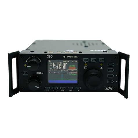
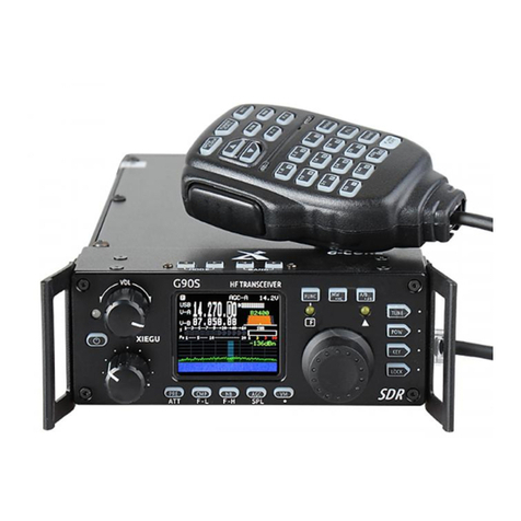
XIEGU G90 User manual

Version 4.3 – May 2023 (for G90 units with firmware v1.8).

2
Ultra-Miniature 24 Bit SDR

3
About Radioddity
“You, our friend and customer, are at the forefront of what we do.”
Thank you for purchasing a XIEGU product from Radioddity. Through a strong
partnership which allows us to bring you the latest technology from the XIEGU
brand and on behalf of Customer Support team, we strive to fulfill our promise
to better meet your needs every day.
In order to protect your rights please read the terms on XIEGU Warranty Card
carefully and know the Warranty Policy.
Firmware Update FAQ Facebook group.
Instructions.
G90 Feedback Survey:
scan to share your suggestions!
We look forward to improving our products based on
customer experience, and any ideas would be appreciated!
If you have any suggestions for new XIEGU products, you’re welcome to
contact us via < support@radioddity.com >.
XPA125B Amplifier G90-H1 stand DE-19 data interface GSOC external controller
Information on all of these and other accessories can be found at www.radioddity.com

4
Warnings
1. Please read this manual fully before operation so as to get a good
understanding of the G90’s capabilities and functions.
2. When using an external mains power supply or battery, carefully check
the polarity of the power cord and do not reverse the polarity.
3. The warranty of this radio does not cover damage caused by an incorrect
external power connection error or damage caused by improper power
supply voltage.
4. Only qualified technicians shall service this equipment.
5. Do not tamper with the transceiver for any reason.
6. Do not operate the transceiver with a damaged antenna. If part of an
antenna comes into contact with your skin, a minor burn can result.
7. Turn off your transceiver prior to entering any area with explosive or
flammable materials.
8. Do not operate your transceiver in any area near explosive or flammable
materials.
9. To avoid electromagnetic interference, please turn off your transceiver in
any area where notices instruct you to do so.
10. Turn off your transceiver before boarding an aircraft; any use of a radio
must be in accordance with airline regulations and crew instructions.
11. Turn off your transceiver before entering any blasting area.
12. Do not place the transceiver over any airbag deployment area in vehicles
containing airbags.
13. Do not expose the transceiver to direct sunlight over a long period of
time, nor place it close to any heat source.
14. When transmitting with the transceiver, hold the microphone 3 to 4
centimeters away from your lips and keep a safe distance away from the
antenna in accordance with the ICNIRP and any additional local
regulations.
Copyright
All rights reserved 2022 Chongqing Xiegu Technology Co., Ltd. Reproduction
of any part of this manual is prohibited without permission.
We would like to extend sincere gratitude to Radioddity's ham friends -- Bob
Nagy (AB5N), Garry F. Decker (W9WHF) and Ed Durrant (DD5LP), for their
instructive advice and useful suggestions in this G90 English manual.

5
Introduction
The G90/S is an amateur radio portable 20W HF transceiver using the latest
24-bit SDR technology. It is a new member of the Xiegu product family and our
first portable SDR model in the new G series.
Based on a 24bit-CODEC, the G90/S brings superior transceiver performance
and a highly configurable user experience. The detachable head design allows
you flexibility to position the radio’s main body where needed. The radio
includes a built-in high-performance ATU capable of matching a very wide range
of antennas.
Features Include:
High-performance RF front end giving superb selectivity
Modes provided are LSB/L-D/USB/U-D/CW/CWR/AM/NFM
1.8-inch-high-contrast color TFT LCD display
±24k bandwidth spectrum & waterfall displays
Adjustable DSP band filters (CW mode can be as narrow as 50Hz)
Built-in CW Decoder
Detachable head unit
Built-in Antenna SWR scanner
Built-in Wide-range automatic antenna tuner
Please read this manual carefully for a better experience and a full
understanding of the operation of the G90/S.
■ The G90S is the version sold in the People's Republic of China, the G90 is
the version available in other countries. This operation manual is applicable
to both models.
Note: As this is a “Software Defined Radio” many things can be changed with a
firmware upgrade. New features can be added and the operational processes
can be changed. Therefore, it is recommended that you ensure your G-90/S is
at the latest firmware level (as of this update of the manual, that was Firmware
v1.79b03 released on October 26th 2022). If the instructions in this manual don’t
appear to work as expected on your G-90/S it is highly likely that you are on a
different firmware version.

6
INDEX
About Radioddity ............................................................................................... 3
Warnings ............................................................................................................ 4
Copyright ........................................................................................................ 4
Introduction ........................................................................................................ 5
Specifications .................................................................................................... 8
Accessories and optional components ........................................................ 10
Interface Definition .......................................................................................... 11
Machine Interface – Front panel ................................................................... 12
Machine Interface - Rear Panel .................................................................... 13
Machine Interface – Head Unit ..................................................................... 14
Hand Microphone Buttons ............................................................................. 16
Power Source Connection ............................................................................. 17
Functions of the buttons ................................................................................ 18
Operation of a button’s second function: ................................................. 19
Screen Display Icons...................................................................................... 19
Function and definition of displayed icons: ............................................. 20
Operation ......................................................................................................... 21
Transceiver start and shutdown ............................................................... 21
To turn off the LCD screen to save power: ............................................. 21
Display of Power Voltage: ......................................................................... 21
Selection of Working Frequency Range .................................................. 22
Operating Mode Selection ......................................................................... 23
Volume adjustment ..................................................................................... 23
Call Sign Editor............................................................................................ 24
Setting Operational Frequency. ................................................................ 24
Adjustment of RF Gain and Muting Level ............................................... 25
Squelch Operation (prior to firmware v 1.75): ........................................ 26
Multi-function Adjustment Knob (from F/W version 1.75 onwards). .... 26
Reception and Transmission Operations using SPL and VFOA/B ..... 27

7
Automatic Gain Control (AGC) ................................................................. 28
PRE-AMP/ATT (combined control) .......................................................... 29
Pulse Interface Suppressor – Noise Blanker .......................................... 29
Voice Compression CMP........................................................................... 30
CW (Morse Code) Communication .......................................................... 30
CW Keyer settings ...................................................................................... 31
SSB Voice Communication ....................................................................... 32
Voice-controlled Transmit - VOX .............................................................. 33
Setting Line level Input into ACC connector: .......................................... 33
Automatic Antenna Tuner .......................................................................... 34
Standing-wave Scanner SWR .................................................................. 34
Corresponding location of keys VS. screen labels: ............................... 35
Fine Tuning of Received Frequency (RIT) .............................................. 35
Line Input and Output ................................................................................. 36
Operation of line output: ............................................................................ 36
Channel Memory Write (MW) and Clear (MC) ....................................... 37
Transmitter Power Setting ......................................................................... 37
Digital (DSP) Filters .................................................................................... 38
Receive filter operation prior to firmware v 1.79b02: ............................. 39
Spectrum/ Waterfall Display ...................................................................... 40
Data Communication .................................................................................. 41
Cable connection steps .............................................................................. 42
Digital Mode Connections .............................................................................. 43
Factory Reset ..................................................................................................... 45
System Menu ............................................................................................... 46
CiV Control Instructions ................................................................................. 49
Band Voltage Data ........................................................................................ 51
Firmware upgrades ............................................................................................ 52

8
Specifications
General parameters
Frequency range: RX: 0.5MHz-30MHz
TX: 1.8-2.0MHz (*1)
3.5-4.0MHz (*1)
5.330.5-5.405MHz (*1 *3)
7.0-7.3MHz (*1)
10.1-10.15MHz
14.0-14.35MHz
18.068-18.168MHz
21.0-21.450MHz
24.89-24.99MHz
28.0-29.7MHz
Operating modes: USB/U-D/LSB/L-D/CW/CWR/AM/FM (*2)
Minimum step: 10Hz
Antenna impedance: 50Ω
Working temperature: 0°C ~ +50°C
Frequency stability:
±1.5ppm in the 10~60min after
startup
@25°C: 1ppm/hour
Power supply voltage: 10.5~16.5VDC, negative ground
Current consumption: Receive: 700mA@ Max
Transmit: 6A@ Max
Case size (mm): 120Wx45Hx210D (case only)
140Wx52Hx250D (with handles)
Weight: About 1.63kg (for main body)
Transmitter parameters
RF output power:
(@ 13.8VDC)
20W(SSB/CW/FM/AM)
Spurious suppression: ≥50dB
Carrier suppression: ≥40dB
Microphone impedance: 200Ω ~10kΩ (most often 600Ω)

9
Specifications (continued)
Receiver parameters
Circuit type: Zero-IF (ZIF) direct conversion SDR.
Neighboring channel suppression: ≥60dB
Sideband suppression: ≥60dB
Sensitivity:
SSB/CW AM
0.5~1.79999MHz / 10uV
1.8~1.99999MHz 0.35uV 10uV
2.0~27.9999MHz 0.25uV 2uV
28.0~30.0MHz 0.25uV 2uV
Measurements made with PRE=on, ATT=off, NB=off, SSB/CW/AM=10dB S/N.
Mirroring suppression: 70dB
Sideband suppression: 60dB
Audio output: 0.5W (8Ω, ≤10% THD)
Audio output impedance: 4~16Ω
♦ The specifications above may be changed without notice.
♦ (*1) The operator is ALWAYS responsible to ensure he/she does not transmit
using the radio outside of the amateur allocation (and in the case of an amateur
without a full authority licence (i.e. entry level or novice) outside of the allocated
frequencies in their licence). Radios that are sold to service the international
market may at times have the ability to transmit on frequencies that are not
available in some countries or under some licence classes. You as the operator
MUST ensure that you do not transmit outside of your authorized frequency
range (do not forget about the sideband(s) when operating close to the edge of
a band).
♦ (*2) FM mode was only fully available from version 1.75 of the firmware prior
to that firmware version it was only available in conjunction with XIEGU’s GSOC
controller. The two data modes U-D and L-D were added in FW v 1.79b02
♦ (*3) The G90/S covers the range needed for the US 60m channels and the
WRTC15 ITU band. It does not cover the bottom half of the UK 60m “bandlets”

10
Accessories and optional components
Included accessories: Quantity
Multi-function hand microphone 1
USB data interface cable: 1
DB9 head unit extension cable: 1
Detachable head fixing studs 2
Hexagonal wrench 1
DC power cord 1
Warranty card 1
Instruction leaflet 1
Quality assurance certificate 1
*Optional accessories:
DE-19: Digital interface unit providing one USB cable to the PC with support for
two-way audio and serial communications as well as providing control of an
optional XPA125B amplifier.
XPA125B: Xiegu 100W power amplifier, including an automatic antenna tuner.
GSOC: external, large screen, controller.
G90-H1: Stand with fan
G90-H2: Tilting front support legs
PAX-100: Radioddity HF 100W PEP amplifier.
GNR 1: Xiegu Digital Audio Noise Filter Unit.
NOTE: The G90/S is dealer modifiable for use on the US MARS required transmit
frequency ranges.
NOTE: Your antenna will have a great impact on the quality of your communications.
Many simple wire antennas offer excellent performance for field operations.

11
Interface Definition
Definition of microphone interface Wiring diagram of COMM plug
Wiring diagram of earphone plug
Left and right connections carry
monaural audio
Rear ACC socket
Wiring of CW keys
Note:
♦ If the connector of the CW key is a 6.5mm 2-wire plug, please change it to a
3-connector 3.5mm stereo plug according to the wiring method shown in the
figure above.
♦ Be careful when using 2-core to 3-core adapters because incorrect wiring may
put the radio into CW transmission mode all the time.
Common
Da
Common
Da
Di
Di
signal

12
Machine Interface – Front panel
1 Volume knob
• Turn the knob to increase or decrease the volume.
• A momentary press alternates between headphone/speaker output.
2 Power supply /transceiver indicator light
• Standby /receive state: yellow-green;
• Red indicates the radio is transmitting.
3 Power (on/off) switch
• When powered-off, a momentary press of this button will turn the radio
on.
• When powered-on, a long press of this button will shut down the radio.
• While starting up, a momentary press of the button will turn off the screen
to save electricity.
4 Multi-function Adjustment Knob
• By default, turning this knob will change the frequency in 100kHz steps.
• A long press of this knob will select custom action functions.
5-6 MODE switching
Pressing these buttons will cycle through all the modes.
7-8 BAND switching
Pressing these buttons will switch up or down through the Amateur bands
or the Amateur and SW Broadcast bands Whether the SW Broadcast
bands are included in the sequence is defined through Function 8 in the
System menu. (Transmission is only allowed in the HAM bands).

13
9 FUNC indicator
This LED will light when the second function of a button is activated.
10 Δ F indicator This LED blinks when the CW signal is tuned in when in CW
mode allowing the CW decoder to work.
11 Main VFO/Mem tuning knob
Change the current frequency by rotating this knob. When setting menu
items this knob changes the parameter’s value.
12 Function keys
The definition and functions of these buttons are detailed in the operation
section of this manual (Pages 17-18).
Machine Interface - Rear Panel
13 Antenna interface
SO-239 type - impedance 50Ω.
14 KEY interface
A 3.5mm stereo jack used to connect manual/paddle CW keys. (See
Page 10 for the wiring details)

14
15 COMM interface
Only used for updating the radio body’s firmware at present.
16 I/Q signal output port
A 3.5mm connector (3 wires) used for IQ signal output.
17 ACC interface
See the interface details on page 10.
18 DC power interface
DC power input (PSU or battery). The round hole is the negative
connection and the square hole is the positive connection.
19 Ground terminal
Good grounding can improve the receiving and transmitting
performance of the G90/S and reduce the possibility of RF ingress.
Machine Interface – Head Unit
20 MIC (microphone) interface (located on the right-hand side)
Used to connect the included multi-function handheld microphone.
21 Headphone interface (located on the left-hand side)
This is a 3.5mm stereo connector (3 wires) used to connect earphones.
(See Page 10 for the wiring details).

15
22 Communication interface (located on the left-hand side)
Used for updating the Firmware of head unit and providing a CAT
control interface to your computer.
Notes:
1. Insert the supplied 3.5mm to USB cable into this port for data transfer or
CAT control mode communications.
2. Do not insert the cable into this port before you start the G90/S up.

16
Hand Microphone Buttons
1. LOCK button Lock button
2. PTT button Press to transmit
3. Up/down
Frequency increase/ decrease button (user-
defined in the system menu)
4. Transmit/receive
indicator light Transmission in progress indicator light
5. Main keypad area Main numeric keypad area
6. FIL button Filter selection (no action on DSP filter)
7. MODE button Selection of the operating mode of the radio
8. Functional indicator light
Lights whenever a key is pressed on the
microphone.
9. Function buttons
F1/F2 buttons (user-defined in the
system
menu) – e.g. preamp / split.
10. MW button Memory channel operation
11. V/M button Frequency/memory channel switch.
12. XFC button No function
13. TUNER button
Momentarily press
ing this button will switch
the ATU in or out of circuit. Pressing in for
a
longer time starts automatic antenna tuning.

17
Power Source Connection
Connect your power supply or battery to the DC-IN connector. Current capability
of the DC power supply should be at least 8 amps. Batteries should supply 10.5-
16.5V DC and have capacity to supply up to 10 amps. Typical current
requirements on transmit are generally less than 8A. Use the provided cable to
connect the G90/S to your DC supply. The G90/S transmitter is designed in
such a way that dropping supply voltage from a weak battery has little effect on
the transmitter output power until 10.5v is reached.
The DC power supply must be connected in strict accordance with the following
figure to avoid a reverse polarity connection.
♦ The red wire must be connected with the positive pole of power supply and
black wire to the negative pole of the power supply.
♦ A Ferrite Choke may be attached to the power wires to prevent external RF
from entering the radio via its power lines and RF interference from inside the
radio from radiating externally via the power cable. When installing a ferrite
choke, place it closest to the radio end of the DC cable.
♦ Polarity of power cables should be checked carefully to avoid reverse
polarity when connecting your power supply or battery.
♦ Although the G90/S has reverse polarity protection reverse connection
of power should be avoided.
Red line
Black line

18
Functions of the buttons
Button First function
(momentary press, cycle)
Second function (FUNC+)
(quick press so light
comes on)
Long press
PRE/ATT PRE - ATT - Normal. cycles through
these
states.
/ /
CMP/F-L Turn on voice compression
Digital filter F-L, low-pass cut-off
frequency selection using the
main tuning knob
Reset filter
parameters
NB/F-H NB ON-NB Level-NB Width
Digital filter F-H, high-pass startup
frequency selection using the
main tuning knob
Reset filter
parameters
AGC/SPL AGC, Fast-Slow-Auto-none. Turn on the split frequency
transceiver operation mode
RF GAIN
VM Switch between frequency and
channel mode.
/ Call Sign Editor
MW/MC
Write channel to
memory
.
Clear c
hannel
entry
/
A/B. A>B Switch between VFO-A and VFO-B Copy the current VFO-A
freq
uency
to
VFO
-
B.
/
TUNE Turn on/off the antenna tuner (in-
circuit/out
-
of
-
circuit)
/ Antenna tuning
POW
POWER Power output setting MICGAIN Hand microphone
MIC gain setting
Standing-wave
scanner display
SWR THR Standing-wave protection
threshold setting
INPUT Audio input
selection
KEY
SPEED Automatic key rate
setting
CW Volume Side tone volume
setting
CW automatic
decoder
M/L/R Manual/automatic left
and right mode switching
CW TONE Side tone
frequency setting
MODE iambic A/B mode
switching /
QSK Insert/non-insert
selection
/
QSK Time
Hang time setting
/
Ratio
Setting of the automatic
key dot-and-dash interval
ratio
/
LOCK Lock / Screen brightness.
SCALE
Spectrum
reference level
setting
Lock button
AVE FFT
Mean value setting,
ranged 1~10
Volume knob
(press) Loudspeaker / earphone switching
VOX ON/OFF
Voice control
switch
/
VOX GAIN Voice control gain
setting
/
ANTI-VOX
Hand microphone
and speaker echo
suppression setting
/
VOX DLY
Voice control
transmission
turnoff delay
/
Multi-knob
(press)
Filter center mode setting
/
/
Filter bandwidth mode setting
/
/
Main knob
(press)
Accept (save) settings Activate RIT /

19
Operation of a button’s second function:
Press the [FUNC] button - the F indicator LED will illuminate, then press the
required function’s button.
Press the [FUNC] button again to exit the secondary function. At this time, the
F indicator LED will go off.
Pressing the [FUNC] button for 1-2 seconds will take you into the System Menu
(see later in this manual for details of parameters that can be set).
■ In any function (including the secondary FUNC setting) a short press of the
main knob will save the setting. This will also exit the function setting mode and
return you to the main interface.
Screen Display Icons
Multi-function indicator
Receiving state is meter s
Transmission state is power
meter
Mode display
Standing-wave display area
Spectrogram display area
Receiving level display
Receive bandwidth indication
Volume indication
Power supply voltage indication
VFO display area
Waterfall diagram display area
Status display area

20
Function and definition of displayed icons:
: pre-amplifier is ON. The icon character A indicates that the attenuator is in-
line. No character indicates Normal mode.
: noise blanker is ON
: automatic antenna tuner is in circuit.
: voice compression CMP is active
: squelch is ON
: voice triggered TX control function is ON
: AGC control is set to Slow (alternatively AGC-F, AGC-AUTO, AGC
settings may be indicated)
: supply voltage display.
: Current operating mode in use – USB, LSB, CW, CW-R, AM or FM.
: As the split mode symbol is indicated between VFO-A and VFO-B, VFO-
A is the current receive frequency and VFO-B is the transmitting frequency.
Without the “Split” indicator the text VFO-A and VFO-B indicate the frequencies
of the two VFOs.
: SPL split frequency receiving & transmitting mode is active.
: Loudspeaker mode. A short press-in of the volume knob switches between
earphone and speaker modes.
: All buttons locked symbol – settings cannot be changed until the buttons
are unlocked again.
: While receiving, the received signal strength
is indicated by the green/red line and can be read off against the top row of
figures. When in transmit mode, the same indicator can be read against the
bottom line indicating the power being transmitted.
R±XXX – displayed under Rx DbM level in the waterfall is the current RIT value.
: During transmission the SWR meter displays the standing-
wave ratio value of your antenna system.
: This chart Indicates the settings of the DSP receiver filter
Other manuals for G90
10
This manual suits for next models
1
Table of contents
Other XIEGU Transceiver manuals
Popular Transceiver manuals by other brands

Entel
Entel HT446 owner's manual

Kenwood
Kenwood TS-480 user manual

Snell & Wilcox
Snell & Wilcox SHDFTRX0WQ2 Operation manual

Technisonic Industries Limited
Technisonic Industries Limited TFM-566 Installation and operating instructions

Kenwood
Kenwood TR-751A Service manual

uAvionix
uAvionix SkyEcho 2 Installation and Pilot's Guide