Prins VSI User manual

MAKE OF AUTOMOBILE:
Renault
TYPE:
Clio 3
PISTON DISPLACEMENT:
1200cc
NUMBER OF VALVES:
16v
ENGINE NUMBER:
D4F (TCe100)
TRANSMISSION TYPE ( MT / AT )
MT
VEHICLE CATEGORIES M or N
M
TYPE VSI INJECTOR ( COLOUR )
Blue, KN8
VERSION ( LPG / CNG )
LPG
INJECTION SYSTEM:
CONTINENTAL SIM32
MODEL YEAR:
2011
SYSTEM APPROVAL NUMBER ( R115 )
E13#R115-000027 VSI-LPG24
LOCATION SYSTEM STICKER
If applicable : right side, centre door post
ENGINE SET NUMBER
359/030001
NUMBER :
076/1906100
DATE :
2014-08-12
Copyright © Prins Autogassystemen B.V. 2011VERSION NR :
2010-07-29 C

TABLE OF CONTENTS
General instructions............................................................................................................................. 2
Required equipment / tools / materials for installing a complete system............................................. 3
Vehicle check....................................................................................................................................... 3
Base diagram....................................................................................................................................... 4
VSI approval numbers.......................................................................................................................... 5
Mounting and connection points .......................................................................................................... 6
Mounting the reducer........................................................................................................................... 7
Water connections............................................................................................................................... 8
Overpressure connection..................................................................................................................... 9
Mounting the inlet manifold couplings................................................................................................ 10
Mounting the ValveCare manifold couplings...................................................................................... 11
Mounting the VSI injector rail............................................................................................................. 12
Mounting the Prins filter unit............................................................................................................... 13
Mounting ValveCare 1........................................................................................................................ 14
Mounting ValveCare 2........................................................................................................................ 15
LPG hoses ......................................................................................................................................... 16
Mounting the VSI computer bracket................................................................................................... 17
Mounting the fuel selection switch ..................................................................................................... 18
Electrical connections ........................................................................................................................ 19
Electrical connections ........................................................................................................................ 20
Insulate all not used wires.................................................................................................................. 20
Electrical connections ........................................................................................................................ 21
Checklist after installation .................................................................................................................. 22
Trouble code chart............................................................................................................................. 23
FOR EXPLANATION AND CIRCUIT DIAGRAMS SEE : INSTALLATION MANUAL GENERAL PART 1 / 2
EXPLANATION OF SYMBOLS :
= IMPORTANT, CAUTION

PAGE 2
076/19060100
Copyright © Prins Autogassystemen B.V. 2011
Renault
Clio 1.2 16v TCe100 2011
VERSION NR : C
2
General instructions
The installation of the system shall be done in accordance with the installation manual provided by Prins
Autogassystemen.
This manual is based on Dutch regulations, always install the system in accordance to the local regulations.
Always download the “general manual ½ “ from our website for basic instructions and diagrams.
Always disconnect the battery when installing the LPG system. Make sure the ignition key is outside the car.
Be aware of central door locking, radio / telephone memory code, alarm system.
Do not place the main fuse into the fuse holder before having completed the installation of the VSI system.
The VSI computer has to be activated by means of the diagnosis software.
In the unlikely event the VSI computer fails, it will automatically switch over to petrol.
Never disconnect the VSI computer connector, unless you have removed the main fuse.
When installing the VSI wiring harness, ensure that it does not run near any of the ignition components.
Solder and insulate all electrical connections.
The wires in the loom are provided with numbers and text. The text on the wire explains the function of the
wire. The wire harness is not model specific, therefore is it may be necessary to adjust the length of the
wires. Ensure maximum care is taken when connecting wiring.
Make professional joints using solder and shrink sleeve. Do not stretch the wiring harness.
No component of the LPG-system shall be located within 100 mm of the exhaust or similar heat source,
unless such components are adequately shielded against heat.
Remove any internal burrs, after having shortened the LPG pipe. (This guarantees the maximum flow
through the pipe without pollution.)
If holes have to be drilled (wear safety glasses) for installing brackets, etc., the drilled holes must always be
treated with an anti-corrosion agent, after the chips have been removed ( especially when mounting a
exterior filler into body work).
After having completed the installation, check the whole system for gas leakage; use a gas leak detection
device. Also check for leak of engine coolant, petrol and air.
Fitting and maintenance is only allowed by Prins Autogassystemen selected LPG engineers.
Failure to follow the instructions in this manual can result in a poor or non-working gas installation or a
dangerous situation.
For maintenance instructions and filter registration see owner manual.
Prins Autogassystemen is not responsible for any damages to people or objects as a result of changes to
Prins products.
Check our website regularly for diagrams, certificates, updates, info-bulletins and product information.
Please fill in the warranty card completely and return it within 8 days after installation.

PAGE 3
076/19060100
Copyright © Prins Autogassystemen B.V. 2011
Renault
Clio 1.2 16v TCe100 2011
VERSION NR : C
3
Required equipment / tools / materials for installing a complete system
-Complete workshop toolbox ( wrenches, screwdrivers, cutters, pliers, ratchet, sockets )
-Car lift
-Portable computer : operating on Windows 98,W2000 or XP.
Internal memory : 16 Mb or more
Memory HD space : 5MB
Screen : 256 colours, advise colours 16 bits or more
Com port : 1 free COM port 1 or COM port 2 with a 9 or 25 pins connector
-Vehicle fuel system scan tool or OBD scan tool Prins ( part nr. 099/99928 )
-Exhaust gas analyser
-Multimeter
-Oscilloscope
-Prins VSI diagnostic software
-Prins VSI serial interface
-Prins VSI break out box ( part nr. 080/70090 )
-Torque wrench ( 10Nm )
-Portable light
-Assortment drill bits 4 to 12 mm
-Assortment cutters ( ø 20, 30, 50, 70 mm )
-Punching tool ø 70 mm
-Round file
-Portable drill or pneumatic drill
-Threading device ( male M6x1, M8x1, M10x1 )
-Pipe-flaring tool ( for 6 and 8 mm copper pipe )
-Air gun
-Vacuum cleaner
-Hot air gun
-Allan spanner for inlet couplings 3,5mm ( part nr. 099//9970 )
-Reducer adjustment tool ( part nr. 099/9960 )
-Molex extraction tool for VSI switch connector ( part nr. 090/9929 )
-Soldering iron, soldering tin
-Wire-stripping pliers
-Adhesive tape
-Adhesive sealant
-Thread locking compound
-Anti-corrosion agent / black body coating
-Gas leak detection device or foam leak spray
-Shrink sleeves
-Engine coolant
Vehicle check
-Check the vehicle drivability on petrol
-Check the fuel system for error codes ( scan tool )
-Check if the catalytic converter is in good condition ( exhaust gas analyzer )
-Check the condition of the ignition system ( spark plugs, cables, coil )

PAGE 4
076/19060100
Copyright © Prins Autogassystemen B.V. 2011
Renault
Clio 1.2 16v TCe100 2011
VERSION NR : C
4
Base diagram

PAGE 5
076/19060100
Copyright © Prins Autogassystemen B.V. 2011
Renault
Clio 1.2 16v TCe100 2011
VERSION NR : C
5
VSI approval numbers
Reducer VSI LPG Prins : E4-67R-010054
Lock-off valve OMB : E8-67R-014327
Lock-off valve Valtek : E4-67R-010041
Injector rail Prins : LPG E4-67R-010093
CNG E4-110R-000021
Filter unit T1 / T2 Prins : LPG E4-67R-010096
CNG E4-110R-000028
Filter unit Keihin : LPG E4-67R-010177
CNG E4-110R-000091
Injector Keihin :LPG E4-67R-010092
CNG E4-110R-000020
Computer VSI- 4 / 6 Prins: LPG E4-67R-010098
CNG E4-110R-000083
LPG hoses Tubithor : LPG E13-67R-010145
CNG E13-110R-000017
Rubia : LPG E4-67R-010068
CNG E4-110R-000003
PAGE 6
076/19060100
Copyright © Prins Autogassystemen B.V. 2011
Renault
Clio 1.2 16v TCe100 2011
VERSION NR : C
6
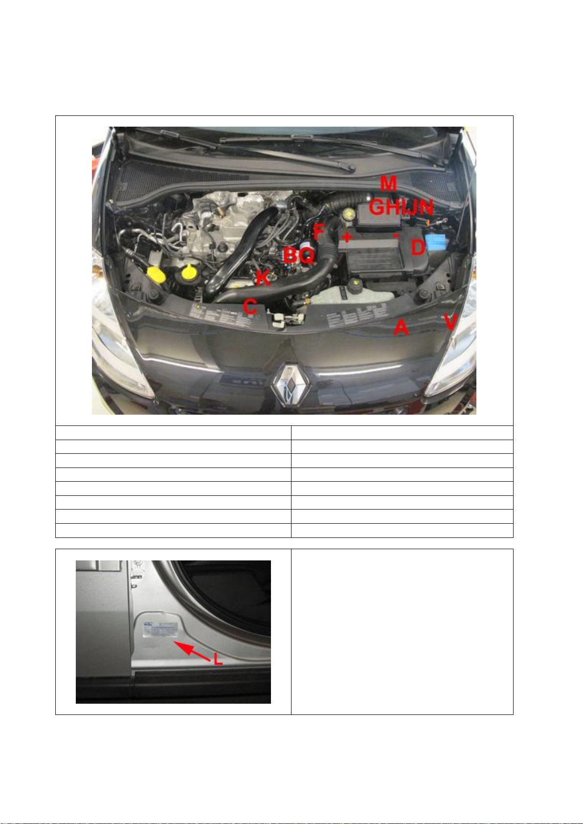
Mounting and connection points
A : Reducer
I : Lambda signal ( 19 + 20 )
B : Filter unit
J : “-“ interruption petrol injector
C : Injector rail
K : Overpressure coupling
D : VSI Computer
L : R115 Approval sticker
E : Injection module
M : grommet
F : Water connections
N : Turbo / MAP signal
G : “+” petrol injectors ( 112 )
V : ValveCare pump
H : Engine speed signal RPM ( 8 )
Q : ValveCare distributor
R115 approval sticker :
Right side centre door post
PAGE 7
076/19060100
Copyright © Prins Autogassystemen B.V. 2011
Renault
Clio 1.2 16v TCe100 2011
VERSION NR : C
7
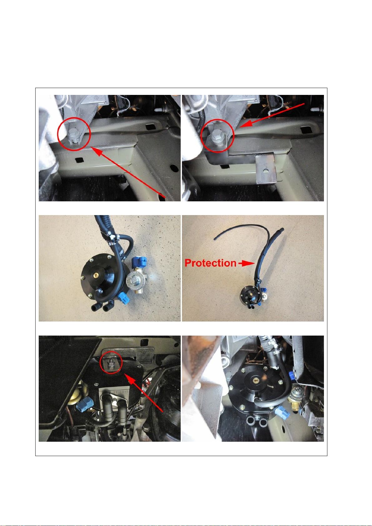
Mounting the reducer
Filter replacement must be recorded in the service book supplied
Remove battery, battery holder and air filter housing.
Mount reducer bracket on original bolt on left chassis beam.
Mount hoses on reducer. For length of hoses see page 16. Mount protection on 16mm hose.
Mount reducer on bracket with M8 nut and spring washer.

PAGE 8
076/19060100
Copyright © Prins Autogassystemen B.V. 2011
Renault
Clio 1.2 16v TCe100 2011
VERSION NR : C
8
Water connections
Cut hoses. Mount T-pieces 20x16x20mm with clamps.
Routing water hoses.
PAGE 9
076/19060100
Copyright © Prins Autogassystemen B.V. 2011
Renault
Clio 1.2 16v TCe100 2011
VERSION NR : C
9
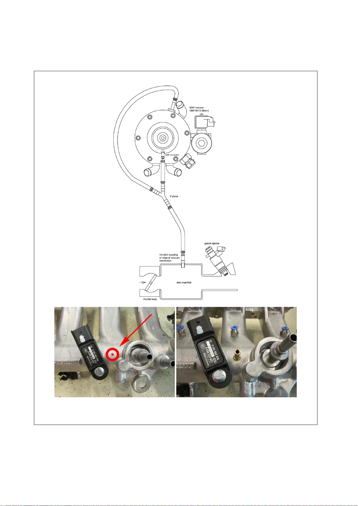
Overpressure connection
Drill a hole of Ø5mm and cut thread M6 in this hole.
Place a VSI coupling with a lock compound to the inlet manifold.
Connect overpressure / MAP hose from reducer.

PAGE 10
076/19060100
Copyright © Prins Autogassystemen B.V. 2011
Renault
Clio 1.2 16v TCe100 2011
VERSION NR : C
10
Mounting the inlet manifold couplings
Remove the inlet manifold. Drill 4x holes of Ø5 mm in the inlet manifold.
Cut M6 thread in these holes.
Place the VSI couplings with a lock compound in the inlet manifold.
Watch out that the lock compound doesn’t come inside the VSI couplings.
Drill 4 holes of Ø5mm at the underside of the inlet manifold. Cut M6 thread in these holes.
Mount the VSI couplings with a locking compound in the inlet manifold.
VSI couplings cylinder 4 & 3. VSI couplings cylinder 2 & 1.

PAGE 11
076/19060100
Copyright © Prins Autogassystemen B.V. 2011
Renault
Clio 1.2 16v TCe100 2011
VERSION NR : C
11
Mounting the ValveCare manifold couplings
Drill 4 holes Ø8,8mm at the upside of the inlet manifold and cut thread G 1/8-28.
Mount the ValveCare couplings with a locking compound in the inlet manifold.
ValveCare couplings cylinder 4 & 3. ValveCare couplings cylinder 2 & 1.

PAGE 12
076/19060100
Copyright © Prins Autogassystemen B.V. 2011
Renault
Clio 1.2 16v TCe100 2011
VERSION NR : C
12
Mounting the VSI injector rail
Mount injector rail bracket at underside of the inlet manifold with M6 bolt, nut and washers.
Mount injector rail on bracket. Connect hoses from injector rail to manifold couplings. Lenghts in cm’s.
Turn “+” battery connection on starter 90 degrees to the front and isolate before mounting back manifold.

PAGE 13
076/19060100
Copyright © Prins Autogassystemen B.V. 2011
Renault
Clio 1.2 16v TCe100 2011
VERSION NR : C
13
Mounting the Prins filter unit
Mount the filter on the left side of the engine on top of the throttle body.
Filter replacement must be recorded in the service book supplied
Mount bracket on top of the throttle body with bolt M6 and spring washer.
Mount filter with supported clamp on bracket and mount hoses.
Mount hoses from reducer to filter and from filter to injector rail. Mount protection on Ø11mm hose.

PAGE 14
076/19060100
Copyright © Prins Autogassystemen B.V. 2011
Renault
Clio 1.2 16v TCe100 2011
VERSION NR : C
14
Mounting ValveCare 1
Mount ValveCare pump on bracket.
Cut wires (except white wire) from diagnostic plug and extend 50cm.
Mount ValveCare hose and mount protection around hose and wiring.

PAGE 15
076/19060100
Copyright © Prins Autogassystemen B.V. 2011
Renault
Clio 1.2 16v TCe100 2011
VERSION NR : C
15
Mounting ValveCare 2
Mount ValveCare pump behind left front plastic wheel arch at the front end of the chassis beam.
Mount ValveCare distributor to bracket. Mount ValveCare hose to distributor.
Mount ValveCare hose to distributor. Mount hoses from distributor to inlet couplings.

PAGE 16
076/19060100
Copyright © Prins Autogassystemen B.V. 2011
Renault
Clio 1.2 16v TCe100 2011
VERSION NR : C
16
LPG hoses
Hose
(Ø..mm)
From component
To component
Hose
length
(cm)
16
Reducer
Prins filter unit
50
11
Prins filter unit
VSI injector rail
30
5
Reducer overpressure
Y-piece
11
5
Reducer MAP connection
Y-piece
32
5
Y-piece
Inlet manifold coupling ( vacuum )
83
5
VSI injector 1
Inlet manifold coupling cyl.1
7,5
5
VSI injector 2
Inlet manifold coupling cyl.2
7,5
5
VSI injector 3
Inlet manifold coupling cyl.3
11
5
VSI injector 4
Inlet manifold coupling cyl.4
15

PAGE 17
076/19060100
Copyright © Prins Autogassystemen B.V. 2011
Renault
Clio 1.2 16v TCe100 2011
VERSION NR : C
17
Mounting the VSI computer bracket
Mark holes for drilling on the left in the battery box.
Drill holes Ø8,5mm and mount computer bracket with supplied plugs.
Before mounting back battery holder, remove lip. Before mounting air filter housing, battery (box) and
VSI2 ECU, connect VSI2 wiring to petrol ECU and push switch wiring through grommet.

PAGE 18
076/19060100
Copyright © Prins Autogassystemen B.V. 2011
Renault
Clio 1.2 16v TCe100 2011
VERSION NR : C
18
Mounting the fuel selection switch
When mounting the switch, only push on its sides.
Pushing the switch in the centre may result in damage to the switch.
Push wiring from switch through grommet. Mark hole for drilling.
Drill hole Ø8,2mm. Mount switch.
Diagnostic plugs behind left head lamp. Mount fuse with original nut next to grounding cable on left
suspension strut.

PAGE 19
076/19060100
Copyright © Prins Autogassystemen B.V. 2011
Renault
Clio 1.2 16v TCe100 2011
VERSION NR : C
19
Electrical connections
Check and measure the wiring in case of changes in the cars wiring colours.
Insulate all not used wires. Alle wires are connected to the GREY petrol ecu connector.
Wire number / code
Wire colour
Connection
1 ground battery
brown
Connect to the ‘–‘ of the battery; use a ring terminal for this
purpose.
32 ground battery sense
brown
Connect to the ‘–‘ of the battery together with VSI wire 1
ground battery.
44 +12V battery
red
Connect to the '+' of the battery; use a ring terminal for this
purpose or solder.
Do not place the fuse in the holder before having completed
the installation of the LPG system.
13 +12V battery sense
red
Connect to the ‘+‘ of the battery together with VSI wire 44
+12V battery.
112 + petrol injectors
red-grey
Make a connection to + petrol injector.
Wire colour : red
Wire location : pos G1
20 AD3 ( lambda 1 )
orange
For the measurement of the lambda signal of cylinder bank 1
Connect the wire in parallel to the lambda sensor.
Wire colour : white - black
Wire location : pos C3
19 AD4 ( lambda 2 )
orange-white
For the measurement of the lambda signal of cylinder bank 2
Connect the wire in parallel to the lambda sensor.
Wire colour : not connected
Wire location :
18 AD1 ( MAP )
blue
For measuring the inlet manifold pressure ( MAP ).
Wire colour : green - black
Wire location : pos A3
17 AD2 ( Valve Care )
Green
White-yellow
Brown
Green-yellow
Red
VSI ecu connector: Pos AD2 (green)
VSI ecu connector: Pos 121 (yellow white)
VSI ecu connector: Pos 1 (brown)
VSI ecu connector: Pos 24 (green-yellow)
VSI ecu connector: Pos 112 (red)
8RPM
purple-white
For measuring the engine speed.
Wire colour : brown
Wire location : pos G4
Table of contents
Popular Automobile Part manuals by other brands

Edelbrock
Edelbrock 5752 installation instructions

Edelbrock
Edelbrock 5683 installation instructions

Hellwig
Hellwig 7705 installation instructions

Ridewell Suspensions
Ridewell Suspensions RSS-233T Installation and service manual

Edelbrock
Edelbrock Russell 641530 installation instructions

Edelbrock
Edelbrock 6668 installation instructions


