Prizer Hoods CFMR600 User manual

IMPORTANT SAFETY INSTRUCTIONS
PLEASE READ COMPLETE INSTRUCTIONS BEFORE PROCEEDING.
INSTALLATION MUST COMPLY WITH ALL LCOAL CODES.
IMPORTANT: Save these instructions for the Local Electrical Inspector’s use.
INSTALLER: Please leave these instructions with this unit for the owner.
OWNER: Please retain these instructions for future reference.
SAFETY Turn power circuit OFF at the service panel and lock panel door
WARNING: before wiring this unit.
1
CAUTION - TO REDUCE THE
RISK OF FIRE, ELECTRIC
SHOCK, OR INJURY TO PEOPLE,
OBSERVE THE FOLLOWING:
1.
2.
3.
CAUTION: FOR GENER AL
VENTILATION USE ONLY. DO NOT
USE TO EXHAUST HAZARDOUS OR
EXPLOSIVE MATERIALS OR VAPOR.
Use this rangehood only in the
manner intended by the
manufacturer. If you have any
questions, contact the
manufacturer - Prizer Hoods.
Before servicing or cleaning the
unit, switch power o at service
panel and lock the service
disconnecting means to prevent
power from being switched on
accidentally. When the service
disconnecting means cannot be
locked, attach a tag to the service
panel to indicate power has been
switched o for maintenance.
Install this rangehood only with
remote fan models rated
maximum 12.8A or in-hood fans
manufactured by Prizer Hoods,
models CFM300, CFM600,
CFM1200.
CAUTION - TO REDUCE THE
RISK OF A RANGETOP GREASE
FIRE:
1.
2.
3.
4.
Never leave cooktop surface
unattended while on high
setting.
Boilovers cause smoke and greasy
spillovers may ignite. Heat oils
slowly on low or medium
settings.
Hood fan should always be ON
when cooking on high heat or
when ambeing foods (i.e.
Crepes Suzette, Cherries Jubilee,
Peppercorn Beef Flambe.)
Clean in-hood fans frequently.
Do not allow grease to
accumulate on fan or bae
lters.
Always use cookware appropriate
for the size of the surface element.
CAUTION - TO REDUCE THE
RISK OF INJURY TO PEOPLE, IN
THE EVENT OF A RANGETOP
GREASE FIRE, OBSERVE THE
FOLLOWING:
1.
2.
3.
4.
5.
SMOTHER FLAMES with a
tight-tting lid, cookie sheet, or
other metal tray. Immediately
turn the gas burner OFF.
PREVENT BURNS. If gas
ames do not extinguish
immediately; EVACUATE
AND CALL THE FIRE
DEPARTMENT.
NEVER PICK UP A FLAMING
PAN as you may sustain burns.
NEVER USE WATER, wet
dish-cloths or towels as a violent
steam explosion will occur.
Use re extinguisher ONLY if:
•
•
•
•
You know you have a class
ABC extinguisher, and you
already know how to operate it.
e re is small and contained
in the area where it started.
e re department is being
called.
You can ght the re with your
back to an exit.

READ AND SAVE
SAFETY PROCEDURES FOR INSTALLING
YOUR NEW PRIZER HOOD (continued)
UPON RECEIVING YOUR HOOD...
2
CAUTION - TO REDUCE THE
RISK OF FIRE, ELECTRIC
SHOCK, OR INJURY TO PEOPLE,
OBSERVE THE FOLLOWING:
CAUTION - FOR GENERAL
VENTILATION USE ONLY. DO
NOT USE TO EXHAUST
HAZARDOUS OR EXPLOSIVE
MATERIALS OR VAPORS.
A.
B.
Installation work and electrical
wiring must be done by a
qualied installer in accordance
with all applicable codes and
standards, including re rated
construction.
Sucient air is needed for proper
combustion and gas exhaustion
through the ue (duct cover) of
fuel burning cooktop to prevent
backdrafting. Follow the
equipment manufacturer’s
e high degree of craftsmanship in the construction
and nish of your hood requires careful handling to
ensure proper installation.
Do not remove your hood from its carton until you are
ready to hang it.
Do not store your hood anywhere other than within the
carton. If it is necessary to remove your hood from the
carton, place it on a blanket or padded area that will
protect your hood from scratches or indentations.
Do not lift the hood by its utensil rail. Place your ngers
under the lower reveal of the hood. Grasp rmly and
lift.
•
•
•
•
Wearing cotton gloves are preferred. ey will protect
the surface from ne scratches and eliminate
ngerprints.
Remove all rings, watches, belt buckles, and jackets
(snaps-zippers) to prevent scratches on the hood.
If applicable, do not remove the cotton annel from your
hood until the installation process is complete. It will be
necessary to remove only a small portion on the
back-side for a wall mounted hood in order to position in
place.
Located within the hood cavity (behind the bae lters)
are component parts and halogen bulbs.
•
•
•
•
C.
D.
E.
guidelines and safety standards
such as those published by the
National Fire Protection
Association (NFPA), and the
American Society for Heating,
Refrigeration and Air
Conditioning Engineers
(ASHRAE), and the local code
authorities.
When cutting/drilling into a wall
or ceiling, avoid damage to
electrical wiring and other
hidden utilities.
In-hood or in-line fans must be
vented to the outdoors.
If a ventilation unit is to be
installed over a tub or shower, it
must be marked as appropriate
for the application and be
connected to a GFCI (Ground
Fault Circuit Interrupter) -
protected branch circuit.
F.
G.
H.
I.
NEVER place a control switch
where it can be reached from a
tub or shower.
CAUTION - TO REDUCE THE
RISK OF FIRE WITHIN WALLS
OR ROOFS, USE ONLY METAL
DUCTWORK.
Install this hood in accordance
with all requirements specied by
the manufacturer of your
cooktop/range.
Install this hood using required
clearance from cooking surface to
combustible material specied in
cooktop installation instructions.
3
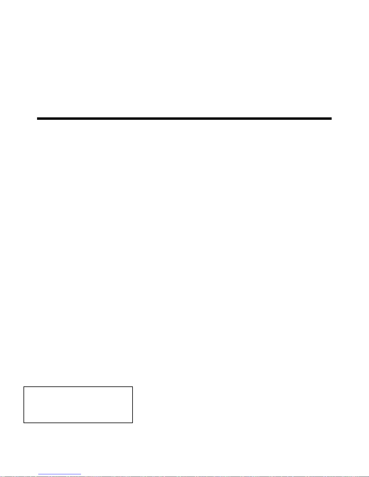
MOUNTING OPTIONS FOR REMOTE FANS
CURB FOR FLAT ROOF
TYPICAL INSTALLATION
DIRECT DUCT INSTALLATION
WALL INSTALLATION
Figure 1.
Figure 2.
Figure 3.
Figure 4.
MOUNTING REMOTE FANS ON ROOF OR OUTSIDE WALL
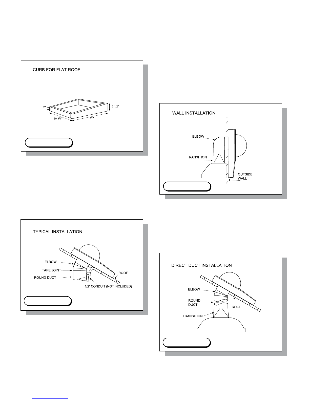
1. Cut out a round hole to accommodate the size ducting you will be using. Cut a second hole for the electrical conduit.
(see Figure 5-C.)
2. When installing a remote fan on a at roof or a roof with a pitch less than 1-1/2” in 12 inches, install the remote fan
in such a way that the discharge (the lowest portion of the curb) is directed away from any prevailing winds.
3. When installing a remote fan on a roof or outside wall, direct the discharge (the lowest portion of the curb) pointing
down the slope as this is in accordance with the Standard Roong Procedures: front discharge edge should be on the
top of the shingles and the rear edge underneath the shingles.
NOTE: e remote fan unit must be sealed between the roof (or outside wall) and the underside of the ange with
roong mastic to prevent leaks.
4. Connect the remote fan (CFMR600, CFMR1000, CFMR1400) to the exhaust system’s round duct. Use an adjustable
elbow to attach to the roof angle.
5. Using duct tape, seal all joints to prevent air leaks.
6. NOTE: Clearance to combustible material is 0”.
Top View Side View
Figure 5-B.Figure 5-A.
Figure 5-C.
Cut Out Dimensions
4
To prepare for mounting a remote fan, inspect the blower wheel to ensure it turns freely. Do not replace the top
unit to the remote fan until the installation has been completed. A remote fan cannot be installed in a condition
where the exhaust/discharge opening is less than 15” from the ground level. NOTE: ere may be some local
codes that will not permit this kind of installation. Heavy snow will prevent the damper from opening due to
snow blockage. e installer must check all local codes for outdoor wall installation of the remote fan.
This manual suits for next models
2
Table of contents
Other Prizer Hoods Ventilation Hood manuals


Popular Ventilation Hood manuals by other brands

Gorenje
Gorenje S3 IHGC963S4X manual

KOBE
KOBE ISX2136SQB-1 Installation instructions and operation manual

U.S. Products
U.S. Products ADVANTAGE-100H Information & operating instructions

Kuppersberg
Kuppersberg DUDL 4 LX Technical Passport

Framtid
Framtid HW280 manual

Thermador
Thermador HGEW 36 FS installation manual


