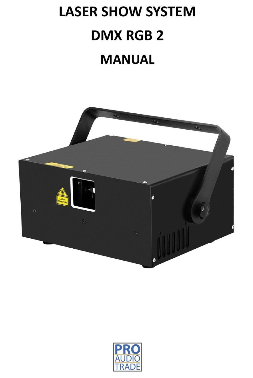
Pro Audio Trade BEAM BOX 5W User manual

LASER SHOW SYSTEM
BEAM BOX 5W
MANUAL

2
CONTENTS
1INTRODUCTION .................................................................................................................................................. 3
2WHAT’S INCLUDED?............................................................................................................................................ 3
3UNPACKING INSTRUCTIONS................................................................................................................................ 3
4GENERAL INFORMATION .................................................................................................................................... 3
5SAFETY NOTES .................................................................................................................................................... 4
6PROPER USAGE................................................................................................................................................... 6
7RIGGING ............................................................................................................................................................. 6
8OPERATION......................................................................................................................................................... 6
8.1 INSTRUCTIONS FOR POWERING ON THE LASER SYSTEM................................................................................ 6
8.2 INSTRUCTIONS FOR TURNING OFF THE LASER SYSTEM.................................................................................. 7
8.3 FRONT &REAR PANEL .................................................................................................................................. 7
8.4 PRODUCT SPECIFICATION............................................................................................................................. 7
8.5 USING FB4 MODULE .................................................................................................................................... 8
8.6 DMX CHANNELS .........................................................................................................................................12
9TECHNICAL INFORMATION: MAINTENANCE AND SERVICE .................................................................................16
9.1 GENERAL CLEANING INSTRUCTIONS: TO BE DONE BY USER ..........................................................................16
9.2 LASER BEAM ALIGNMENT: TO BE DONE BY USER OR MANUFACTURER..........................................................16
10 INSTRUCTIONS FOR BEAM ALIGNMENT.........................................................................................................16
11 INSTRUCTIONS FOR USING E-STOP SYSTEM ...................................................................................................17
12 SERVICE .........................................................................................................................................................18

3
1INTRODUCTION
Thank you for purchasing Beam Box 5W! To optimize the performance of your laser, please read
these operating instructions carefully and familiarize yourself with the basic operations of this
system. These instructions contain important safety information regarding the use and maintenance
of this system as well. Please keep this manual with the unit, for future reference. If you sell this
product to another user, be sure that they also receive this document.
Notice
We are constantly striving to improve the quality of our products. As such, the content of this
manual may be changed without notice.
We have tried our best to guarantee the accuracy of this manual. If you have any questions or
find any errors, please contact us directly to help address this.
2WHAT’S INCLUDED?
NAME
PCS
Remark
Laser projector
1
Power cord
1
Keys for projector key switch
2
Ethernet cable 5 meters
1
3-pin interlock bypass plug
1
Used on projector when not connecting the E-STOP BOX
User guide
1
3UNPACKING INSTRUCTIONS
Open the package and carefully unpack everything inside.
Ensure all parts are present and in good condition.
Do not use any equipment that appears to be damaged.
If any parts are missing or damaged, then please immediately notify your carrier or local
distributor.
4GENERAL INFORMATION
The following chapters explain important information about lasers in general, basic laser safety
and some tips about how to use this device correctly. Please read this information as it contains
critical information you must be aware of, prior to using this system.

4
5SAFETY NOTES
WARNING! This projector is a Class 4 laser product. It must never be used for audience-scanning
applications. The output beam of the projector must always be at least 3 meters above the floor
in the audience. See the ‘Proper Usage’ for further information.
Please read the following notes carefully! They include important safety information about the
installation, usage, and maintenance of this product.
Keep this manual for future consultation. If you sell this product to another user, be sure that
they also receive this document.
Always make sure that the voltage of the outlet to which you are connecting this product is
within the range stated on the decal or rear panel of the product.
This product is not designed for use outdoors in adverse weather conditions. To prevent risk
of fire or shock, do not expose this product to rain or moisture.
Always disconnect this product from the power source before cleaning it or replacing the fuse.
Make sure to replace the fuse with another of the same type and rating.
If mounting it overhead, always secure this product to a fastening device using a safety chain
or cable.
In the event of a serious operating problem, stop using the projector immediately. Never try
to repair the unit except in a controlled environment under trained supervision. Repairs
carried out by unskilled people can lead to damage or malfunction of the unit, as well as
exposure to dangerous laser light.
Never connect this product to a dimmer pack.
Make sure the power cord is not crimped or damaged.
Never disconnect the power cord by pulling or tugging on the cord.
Never carry a product from the power cord or any moving part. Always use the hanging/
mounting bracket or the handles.
Always avoid eye or skin exposure to direct or scattered light from this product.
Lasers can be hazardous and have unique safety considerations. Permanent eye injury and
blindness is possible if lasers are used incorrectly. Pay close attention to each safety REMARK
and WARNING statement in this user manual. Read all instructions carefully BEFORE operating
this device.
Never intentionally expose yourself or others to direct laser light.
This laser product can potentially cause instant eye injury or blindness if laser light directly
strikes the eyes.
It is illegal and dangerous to shine this laser into audience areas, where the audience or other
personnel could get direct laser beams or bright reflections into their eyes.
No service allowed by customer. There are no user serviceable parts inside the unit. Do not
attempt any repairs yourself.
Service is only to be handled by the factory or authorized factory trained technicians.
Product is not to be modified by the customer.
Caution: use of controls or adjustments or performance of procedures other than those
specified herein may result in hazardous radiation exposure.

5
Laser light is different from any other light sources with which you may be familiar. The light from
this product can cause eye and skin injury if not set up and used properly. Laser light is thousands
of times more concentrated than light from any other kind of light source. This concentration of
light can cause instant eye injuries, primarily by burning the retina (the light sensitive portion at the
back of the eye). Even if you cannot feel “heat” from a laser beam, it can still potentially injure or
blind you or your audience. Even very small amounts of laser light are potentially hazardous even at
long distances. Laser eye injuries can happen quicker than you can blink. It is incorrect to think that
because these laser entertainment products use high speed scanned laser beams, that an individual
laser beam is safe for eye exposure. It is also incorrect to assume that because the laser light is
moving, it is safe. This is not true.
Since eye injuries can occur instantly, it is critical toprevent the possibility of any direct eye exposure.
It is not legal to aim this laser projector into areas where people can be exposed. This is true even if
it is aimed below people’s faces, such as on a dance floor.
Do not operate the laser without first reading and understanding all safety and technical data
in this manual.
Always set up and install all laser effects so that all laser light is at least 3 meters (9.8 feet) above
the floor on which people can stand. See the “Proper Usage” section later in this manual.
After set up, and prior to public use, test the laser to ensure proper function. Do not use if any
defect is detected.
Avoid eye or skin exposure to direct or scattered light.
Do not point lasers at people or animals.
Never look into the laser aperture or laser beams.
Do not point lasers in areas where people can potentially be exposed, such as balconies, etc.
Do not point lasers at highly reflective surfaces, such as windows, mirrors and shiny metal
objects. Even laser reflections can be hazardous.
Never point un-terminated laser beams into the sky.
Do not expose the output optic (aperture) to cleaning chemicals.
Do not use the laser if the housing is damaged, open, or if the optics appear damaged in any
way.
Never leave this device running unattended.
This product must always be operated by a skilled and well-trained operator who is familiar
with the data included in this manual.
The legal requirements for using laser entertainment products vary from country to country.
The user is responsible for the legal requirements at the location/ country of use.
Always use appropriate lighting safety cables when hanging this projector overhead.
Class 4 laser projector - Avoid eye and skin exposure to direct or scattered light!
This laser product is designated as Class 4 during all procedures of operation.

6
6PROPER USAGE
This product is for overhead mounting only. For safety purposes, this projector should be mounted
on steady elevated platforms or sturdy overhead supports using suitable hanging clamps. In all cases,
you must use safety cables.
International laser safety regulations require that laser products must be operated in the fashion
illustrated below, with a minimum of 3 meters (9.8 ft.) of vertical separation between the floor and
the lowest laser light vertically. Additionally, 2,5 meters of horizontal separation is required
between laser light and audience or other public spaces.
7RIGGING
Be sure that the structure onto which you are mounting this product can support its weight.
Mount the product securely. You can do this with a screw, a nut, and a bolt. You may also use
a mounting clamp if rigging this product onto a truss. The U-shaped support bracket has three
mounting holes which may be used to secure the clamps to the projector.
When mounting this product overhead, always use a safety cable.
Always consider ease of access to the unit before deciding on a location for this product.
Caution: use of controls or adjustments or performance of procedures other than those specified
herein may result in hazardous radiation exposure.
This laser product is designated as Class 4 during all procedures of operation.
8OPERATION
8.1 INSTRUCTIONS FOR POWERING ON THE LASER SYSTEM
1. Connect power cable. Turn on the projector.
2. Turn on the key switch on the rear of the projector.
3. Connect the 3-pin XLR interlock bypass plug to the rear of the projector. (If you use the E-STOP
BOX system, then connect the 3-pin interlock cable between the E-STOP BOX and projector, pull
up the red mushroom switch and turn on the key switch. Press the start button.)
4. Connect the Ethernet cable(s) to the projector and computer, and then select the pattern on
software (using Pangolin Quickshow or Beyond software on computer to control). Notice: please
choose “Allow laser output” in software.

7
8.2 INSTRUCTIONS FOR TURNING OFF THE LASER SYSTEM
1. Turn off the key switch. (We recommend having a professional operator to keep the keys, the
3-pin interlock plug and E-STOP BOX.)
2. Turn off the power to the projector via the power switch.
8.3 FRONT & REAR PANEL
NO.
Name
Function
1
Laser aperture
Laser output, do not look directly into this aperture
2
DMX interface
For FB4 DMX control
3
FB4
FB4 control system, with Ethernet and SD card
4
ILDA out
To transfer FB4 signal output with ILDA interface
5
Power ON/OFF
Power switch
6 3-pin interlock
The 3-pin XLR bridging plug supplied has to be plugged into the
interlock socket in order to be able to activate the laser.
7
Key switch
Key switch for laser output
8 Power in and out
AC100~240V power input and output sockets. With output feature
you can connect the device to one another using the input and
output sockets. They must be the same fixtures. DO NOT mix fixtures!
8.4 PRODUCT SPECIFICATION
Voltage
AC 100~240V, 50/60Hz, T3A
Power rate
250W
Unit dimensions
238*246*163mm (without the bracket)
Net weight 8KG
Total laser output 5W
Laser source
1200mW Red 638nm; 1700mW Green 525nm; 2200mW Blue 455nm
Scanner system
30kpps@ILDA 8
Working temperature
10~40
℃
Cooling system
Fan cooling

8
8.5 USING FB4 MODULE
8.5.1 Getting started
When using FB4 for the first time. Take the following steps:
1. Make sure the included microSD card is properly inserted in the microSD slot
2. Connect an ethernet cable between the network port on FB4 and your computer
3. Turn on the power to FB4
4. Wait until FB4 has acquired an IP address. The yellow LED should blink once a second.
(See the section “Status LEDs” for more information)
5. Start Pangolin Laser Show Designer QuickShow on your computer
6. The PC should now connect to FB4
8.5.2 Operation modes
Beyond/QS In Beyond/QS mode, FB4 connects to Pangolin Quickshow or Beyond software via an
ethernet network. Geometric correction is being handled by the control software and native
geometric correction on FB4 is turned off to avoid conflicts.
ILDA Input In ILDA input mode, the signals from the ILDA input connector on the FB4-ILDA
daughterboard are transmitted to the color and axis output connectors on FB4. In this mode,
native geometric correction on FB4 is turned off.
DMX-512 In DMX-512 mode, FB4 is being controlled through the DMX input port on the FB4-DMX
daughterboard. The content is stored on the SD card and FB4 can apply multiple effects to them.
In this mode, geometric correction can be applied natively on FB4.
ArtNET In ArtNET mode, FB4 is being controlled with an ArtNET signal via the ethernet port on
FB4. The content is stored on the SD card and FB4 can apply multiple effects to them.
In this mode, geometric correction can be applied natively on FB4.
Autoplay In autoplay mode, FB4 can be configured to play laser content from the SD card without
any external input. FB4 can be programmed to play single cues or entire playlists of cues
immediately after power-up or at specific times.
In this mode, geometric correction can be applied natively on FB4.
Time Code In time code mode, FB4 plays content from the SD card in sync with an external
timecode source. FB4 can receive ArtNET timecode via the ethernet connector.
In this mode, geometric correction can be applied natively on FB4.
Slave Mode In slave mode, FB4 plays content from the SD card in sync with a “Master” FB4 which
is working in autoplay mode. The ethernet network is being used to synchronize the FB4s.

9
In this mode, geometric correction can be applied natively on FB4.
Test mode Test mode can be used to play test patterns from the SD card for the purpose of testing
your laser or adjusting FB4’s internal parameters or geometric correction.
8.5.3 User interface
To modify settings and change operating modes, the control knob can be used in conjunction with
the OLED display.
Activating the display
Press the knob once to activate the display.
The bar on the top displays the current operation mode of FB4. The white arrow can be moved
between menu items by rotating the knob. Pushing the knob will activate the menu item next to
the arrow.
The items displayed in the menu may vary between different operation modes and when different
accessory boards are connected to FB4.
Changing operation mode
In this example, we will demonstrate how to change the operation mode from Beyond to ILDA
input. The menu item “ILDA Input” may not be present on your FB4 is there is no “FB4-ILDA”
daughterboard connected.
After activating the display, turn the knob until the arrow points at the menu item “Operation
Mode”.

12
Red LED (Emission status)
Legend
8.6 DMX CHANNELS
FB4 16 Channel DMX Profile layout
Channels
Value
Function
Description
Width
1 0-255 DMX Modes 0-31 Blackout
33-95 Four channels
97-159 Eight channels
161-232 Twelve channels
225-255 Sixteen channels
8 Bit
2 0-255 Page index
(9 pages in total)
0-15 Page 1
17-31 Page 2
33-47 Page 3
8 Bit

13
Channels
Value
Function
Description
Width
49-63 Page 4
65-79 Page 5
81-95 Page 6
97-111 Page 7
113-127 Page 8
129-255 Page 9
3 0-255 Cue Index
(48 cues in total)
0-32 None active
33-35 Cue 1
37-39 Cue 2
.. - .. ..
221-223 Cue 48
225-255 Repeat
8 Bit
4 1) 0-255 Cue Speed 0-15 Full Speed
17-31 Pause
33-255 25 till 200%
8 Bit
5 0-255 Dimmer 0 till 100% 8 Bit
6
0-255
Zoom
0 till 100%
8 Bit
7 0-255 Size X -100 till 100% 8 Bit
8
0-255
Size Y
-100 till 100%
8 Bit
9 0-255 Angle Z 0 till 360 degrees 8 Bit
10
0-255
Position X
0 = left
128 = Center
255 = Right
8 Bit
11
0-255
Position Y
0 = top
128 = center
255 = bottom
8 Bit
12
0-255
Visible points
Zero Points till 100% of points visible
8 Bit
13 2) 0-255 Scan Rare 0-31 Cue preferred speed
33-223 6K till 29K
225-255 30K
8 Bit
14
0-255
Cue release
0-31 Default
33-95 Hold
97-159 Loop
161-223 Next
225-255 Stop
8 Bit

14
Channels
Value
Function
Description
Width
15 0-255 Color Scroll 0-31 Original cue color
33-223 Color Scroll
225-255 White
8 Bit
16 0-255 Reserved Reserved 8 Bit
39 Channel DMX Profile layout
Channels
Value
Function
Description
Width
1
1)
0-255
Fixture
Modes
0-239 Blackout / Safe
240-240 Setup Mode
251-251 Playback mode
8 Bit
2 0-255 Max
Intensity
Defines the max intensity that can be used during
playback mode
(Range 0 till 100)
8 Bit
3 0-255 Test frames Allows enabling test frames during setup mode\\(1=
test frame 1, 255 = test frame 255)
8 Bit
4,5 0-
65535
Size X Defines the maximum width that can be used during
playback mode
(Range -100 till 100%, 0 = 32768)
16 Bit
6,7 0-
65535
Size Y Defines the maximum height that can be used during
playback mode
(Range -100 till 100%, 0 = 32768)
16 Bit
8,9 0-
65535
Position X Defines the maximum height that can be used during
playback mode
(Range -100 till 100%, 0 = 32768)
16 Bit
10,11
0-
65535
Position Y
Defines the horizontal position that can be used
during playback mode
(Range -100 till 100%, 0 = 32768)
16 Bit
12,13 0-
65535
Rotation Z Defines the rotation angle that can be used during
playback mode
(Range 0 till 360 degrees)
16 Bit
14 0-255 Pages Page Index, 255 pages in total
1 = page 1, 255 = page 255
8 Bit
15 0-255 Cues Cue Index, 255 Cues in total
(1 = cue 1, 255 = cue 255)
8 Bit
16 2) 0-255 Cue Speed (0 = Original, 1 – 255 = 1% till 255%) 8 Bit

15
Channels
Value
Function
Description
Width
17 0-255 Dimmer Defines the maximum brightness limited by setup
mode
(Range 0 till 100%)
8 Bit
18,19 0-
65535
Zoom Allows to zoom the cue limited by setup mode
(Range 0 till 100%)
16 Bit
20,21 0-
65535
X Size Defines the maximum width limited by setup mode
(Range -100 till 100%, 0 = 32768)
16 Bit
22,23 0-
65535
Y Size Defines the maximum height limited by setup mode
(Range -100 till 100%, 0 = 32768)
16 Bit
24,25 0-
65535
Z Angle Defines the rotation angle limited by setup mode
(Range 0 till 359 degrees)
16 Bit
26,27 0-
65535
Z Rotation Continues rotation from -60 till 60 Rpm
Range, 0 = Original
1 till 32767 = -100% till -1% rotation
32768 = keep angle but do not rotate
32769 till 65535 = 1% till 100% rotation
16 Bit
28,29 0-
65535
X Position Allows for changing the horizontal position of the cue
limited by setup mode
(Range -100 till 100%, center = 32768)
16 Bit
30,31 0-
65535
Y Position Allows for changing the vertical position of the cue
limited by setup mode
(Range -100 till 100%, center = 32768)
16 Bit
32 3) 0-255 Scan Rate Defines the painting speed of the laser beam.
(5k till original 30K)
8 Bit
33 0-255 Red Intensity range from 0 till 100% 8 Bit
34
0-255
Green
Intensity range from 0 till 100%
8 Bit
35 0-255 Blue Intensity range from 0 till 100% 8 Bit
36 0-255 Alpha Allows you to shift between original cue color or RGB
control.
(Range, 0 = original, 1-255 = 0 till 100% alpha
blending)
8 Bit
37 0-255 Points start Allows you to remove points from the start point of a
cue
(Range from 100 till 0% visibility)
8 Bit
38 0-255 Points End Allows you to remove points from the end point of a
cue
(Range from 1000 till 0% visibility)
8 Bit

16
Channels
Value
Function
Description
Width
39 0-255 Strobe 0 = Strobe disabled
1-255 = Strobe from 1 to 20 Hz
8 Bit
MORE INFO & TUTORIAL VIDEOS ABOUT THE FB4 MODULE CAN BE FOUND ON THE PANGOLIN FB4 WIKI PAGE
https://wiki.pangolin.com/doku.php?id=hardware:fb4
9TECHNICAL INFORMATION: MAINTENANCE AND SERVICE
9.1 GENERAL CLEANING INSTRUCTIONS: TO BE DONE BY USER
Due to fog residue, smoke, and dust cleaning the external body of the projector should be carried
out periodically to optimize light output. Cleaning frequency depends on the environment in which
the fixture operates (smoke, fog residue, dust, dew). In heavy club use we recommend cleaning on
a monthly basis. Periodic cleaning will ensure longevity, and crisp output.
Unplug the product from power.
Wait until the product is cold.
Use a soft damp cloth to wipe down the outside projector casing.
Use compressed air and a brush to wipe down the cooling vents and fan grill(s).
Clean the glass panel (laser aperture) with glass cleaner and a soft cloth when dirty.
Gently polish the glass surface until it is free of haze and lint.
Always be sure to dry all parts completely before plugging the unit back in.
9.2 LASER BEAM ALIGNMENT: TO BE DONE BY USER OR MANUFACTURER
!
This procedure should be conducted only in a controlled environment and with
extreme caution. When aligning the beams, it is recommended to wear sufficient
laser safety protection and to avoid accidental exposure to Class 4 laser radiation.
There is all-in-one RGB laser module inside this laser projector. The module is one of each primary
colors of red, green and blue. The goal is to have all 3 colors overlay each other as perfectly as
possible. The easiest way to test and achieve alignment is to project a large circle onto a suitable
surface (fire safe surface). It is recommended to have as much distance between the projector and
the terminating wall as possible. It is also recommended to perform the alignment using the least
amount of power that enables all the laser modules.
10 INSTRUCTIONS FOR BEAM ALIGNMENT
1. Stand behind the projector and point the laser towards a large flat safe surface.
2. Remove the top panel 4 hex button bolts.
3. Slowly and carefully remove the top cover and set it aside. It won’t be used during this procedure.
4. While standing behind the laser, power up the system as normal.
5. Project a large white circle onto a laser safe surface. Use the least amount of power that enables
all the laser modules.
6. Using a hex key, reach down into the laser from above; adjust the alignment hex button screws

17
on the combining optics until all the beams overlay each other perfectly.
!
Take extra care to avoid interrupting the laser beam with any tools. Class 4 laser
reflections could result.
7. Once the alignment is satisfactory then power down the system.
8. Replace the top panel and replace the hex button bolts.
11 INSTRUCTIONS FOR USING E-STOP SYSTEM
The E-STOP BOX is used to switch off any connected effect lasers directly in the event of a hazard.
Once there is an emergency issue, laser can be shut down immediately by pushing the mushroom
switch, or turn off the KEY switch on the E-STOP BOX.
Connect the E-STOP BOX to the 3-pin interlock connector on the rear of the laser projector using a
3-pin XLR cable.
NO.
Name
Function
1 Laser emission LED
After pressing START button, this LED will keep flashing. It takes
about 10 seconds for activating laser output. The LED indicator will
stay steady ON as soon as the laser beam is emitted.
2 START
VERY IMPORTANT! Every time the laser is shut down, it will be
required to press this START button again, to restart laser emitted.
3
Key switch
Key switch for laser on and off.
1
2
3
4

18
4
Mushroom switch
Push to shut off laser. Release to have laser on.
The diagram below outlines the pinout configuration for the 3-pin connection from E-STOP BOX
to the rear of the projector.
The interlock uses pins 1, 2 and 3.
1. Pins 1 and 3 are the interlock signal. Breaking the connection on pins 1 and 3 will shut down the
projector.
* For example, push the mushroom switch on the E-STOP BOX, or turn off the KEY switch on the
E-STOP BOX will shut down the projector. The projector will then need to be restarted by START
button on the E-STOP BOX.
* It is to be noted that ANY break in an interlock circuit or E-STOP circuit will require a projector
restart from the momentary START button on the E-STOP BOX.
2. Pins 1 and 3 pass restart signal and should be passed as uninterrupted from the E-STOP BOX.
3. Pins 1 and 2 pass bicolor LED and should be passed to projector as uninterrupted from the E-
STOP BOX.
12 SERVICE
There are no user serviceable parts inside this unit. Do not attempt any repairs yourself; doing so
will void your manufactures warranty. In the unlikely event your unit may require service please
contact us directly or your local distributor, who will help you with a repair or replacement. We
will not accept any liability for any resulting damages caused by the non-observance of this
manual or any unauthorized modification to this unit.

SYSTÈME DE SPECTACLE LASER
BEAM BOX 5W
MANUEL D'INSTRUCTIONS

2
INDICE
1INTRODUCTION................................................................................................................................................... 3
2QU'Y A-T-IL DANS L'EMBALLAGE?........................................................................................................................ 3
3INSTRUCTIONS DE DÉBALLAGE............................................................................................................................ 3
4INFORMATIONS GÉNÉRALES................................................................................................................................ 3
5CONSIGNES DE SÉCURITÉ .................................................................................................................................... 4
6UTILISATION........................................................................................................................................................ 6
7GRÉEMENT.......................................................................................................................................................... 6
8FONCTIONNEMENT............................................................................................................................................. 7
8.1 INSTRUCTIONS POUR LA MISE EN MARCHE DU SYSTÈME LASER..................................................................... 7
8.2 INSTRUCTIONS POUR ETEINDRE LE SYSTEME LASER ...................................................................................... 7
8.3 PANNEAU AVANT ET ARRIÈRE...................................................................................................................... 7
8.4 SPÉCIFICATIONS DU PRODUIT ....................................................................................................................... 8
8.5 UTILISATION DU MODULE FB4 ...................................................................................................................... 8
8.5.1. MISE EN ROUTE ............................................................................................................................................ 8
8.5.2. MODES DE FONCTIONNEMENT ......................................................................................................................... 8
8.5.3. INTERFACE UTILISATEUR .................................................................................................................................. 9
8.6 VOYANTS D’ÉTAT ..............................................................................................................................................11
8.7 CANAUX DMX..............................................................................................................................................13
9INFORMATIONS TECHNIQUES: MAINTENANCE ET SERVICE ................................................................................16
9.1 INSTRUCTIONS GÉNÉRALES DE NETTOYAGE: ÀEFFECTUER PAR L'UTILISATEUR ..............................................16
9.2 ALIGNEMENT DU FAISCEAU LASER: ÀEFFECTUER PAR L'UTILISATEUR OU LE FABRICANT ................................17
10 INSTRUCTIONS D'ALIGNEMENT DU FAISCEAU LASER......................................................................................17
11 MODE D'EMPLOI SYSTÈME D'ARRÊT D'URGENCE ...........................................................................................17
12 SERVICE..........................................................................................................................................................19
Table of contents
Languages:
Other Pro Audio Trade Dj Equipment manuals