Pro Co Sound Momentum md16ae User manual

1
Momentum md16ae Manual
16x16 AES3/EBU Digital Interface
Manual
Pro Co Sound, Inc.
225 Parsons Street | Kalamazoo, MI 49007
1-888-253-7360 | www.procomomentum.com
md16ae

2
Momentum md16ae Manual
Pro Co Sound guarantees Momentum for five years, any excuse, even abuse. If you need to return the
Momentum unit(s), ship them to Pro Co Sound in the original carton or a suitable shipping container via
insured freight. Pro Co will return the Momentum unit(s) to you, free of charge including return postage.
Once out of Warranty, Pro Co also offers service on all its products.
Customer Responsibility:
Please read the owner’s manual thoroughly before operating the system. Complete the Warranty Card
within ten days after receipt of your Momentum system. Mail the card to us or register your product on line
at www.procomomentum.com.
The Warranty is subject to the following conditions:
1. Pro Co Sound or its authorized representative or dealer must perform all warranty servicing of the
units, otherwise all aspects of this warranty are void.
2. All tamper-proof seals on the unit(s) must be intact in order for the unit(s) to be serviced as a
warranty claim.
How obtain Warranty services:
If, after following all of the operating instructions in this manual, you find that service or support is still
needed:
1. First contact the dealer or contractor from which you purchased your Momentum product for help.
2. If your problem is not resolved after contacting your dealer, call Pro Co Sound at 1-800-253-7360 and
ask for Momentum Service. Our hours are 8:00 a.m. to 6:00 p.m. EST, Monday through Friday.
If the problem cannot be resolved remotely, Pro Co Sound may, at its discretion, advance the replacement of
the defective unit(s) and at that time provide a Return Authorization number by which the defective unit(s)
can be returned for credit or repair.
Warranty
Revision date: 5/28/08

3
Momentum md16ae Manual
Warranty
Safety Precautions
Welcome
Thank You
Unpacking
Chapter 1: Overview
Momentum System
Features
The Network
The md16ae
The md16ae Enclosure
Front Panel
Rear Panel
Pin Out Diagram
Chapter 2: Connection and Startup
Power
Network Wiring
Copper Wiring
Copper Connection
Fiber Connection
Network Configurations
Clock Configurations
External Clock
Momentum Clock
AES3 Clock
Setup
Network Clock Sync
Using the Control Panel
Setting Device
Start Channel
IP Address
Sample Rate
Clock
Chapter 3: Control Panel Functions
F1 and F2 Functions
Description of Functions
Chapter 4: md16ae Specifications
2
4
5
6
7
8
8
10
10
5
5
6
6
6
Table of Contents
11
17
17
17
18
18
18
18
19
19
20
22
6
7
9
10
10
10
14
14
15
16
18

4
Momentum md16ae Manual
1. Read these instructions carefully.
2. Retain these instructions for future reference.
3. Heed all warnings.
4. Follow all instructions.
5. Do not use any part of this apparatus near water.
6. Do not block any ventilation openings.
7. Do not install near any heat source.
8. Do not defeat the safety purposes of the polarized or grounding type plugs.
9. Do not use the Momentum power supply for any purpose other than stated in this manual.
10. Only use Pro Co recommended accessories with any Momentum device.
To reduce the risk of fire or electrical shock, do not expose
any part of your Momentum System to rain or moisture.
To reduce the risk of electrical shock, do not remove cover. There are no
user serviceable parts inside. Refer servicing to service personnel.
Always follow the basic precautions listed below to avoid the possibility of physical injury to
you or others, or damage to the device or other property. These precautions include, but are
not limited to, the following:
Use Extreme Caution!
Before making adjustments to your Momentum system, be aware that certain actions could possibly
damage your hearing and/or the audio system itself. Think through your actions and the possible
ramifications of your adjustments. Proceed with caution and follow these important Safety Instructions:
Safety Precautions

5
Momentum md16ae Manual
Thank you for your recent purchase of the Pro Co Momentum md16ae. We hope you find our prod-
uct to be versatile and flexible. The entire line of Momentum products was designed with the intention
of offering optimal flexibility for multitude of applications.
Pro Co Sound, a Michigan based business, was founded in 1974. We build audio interface products,
in-ear monitor controllers and facility distribution systems. We continue to live by our mission;
“To become our customers’ very best partner, by building a world class organization, through contin-
ual, rapid improvement in all that we do, and to share in the successes and failures of our efforts.”
Welcome to the Pro Co Family.
When receiving your Momentum System, please check all cartons for damage. If there is damage,
notify the shipper and dealer in that order. Before removing any components of your Momentum
System from the shipping cartons, be sure that the order is complete as expected. Do this by check-
ing each Momentum System component on your packing slip to be sure it matches the number of
packing boxes and the specific type and number of components contained within. Fill out the war-
ranty cards and send them in! You should find the following in the carton:
1 x md16ae 2 x Stage Boots (optional)
2 x Rack Ears 1 x One Spot Power Supply
Welcome
Thank You
Receiving Your Momentum md16ae
NOTE: Stage boots may be requested, for no additional charge at time of order.

6
Momentum md16ae Manual
The Momentum network uses standard Gigabit Ethernet technology. With using standard Ethernet
technology, the Momentum system can be setup and controlled using standard Ethernet products.
Chapter 1
Overview
M
omentum
Sy
stem
Fea
t
u
r
es
The Momentum digital snake system by Pro Co is designed to replace traditional analog audio wiring
anywhere audio distribution is needed. By capturing audio at the source, converting it to digital audio
and distributing it over a standard Ethernet network, many of the difficulties in executing the increasingly
complicated audio systems of today can be simplified. By reducing the amount of field terminations,
installation becomes less time consuming. Texas Instrument, Burr Brown mic preamps and Cirrus Logic
digital converters provide a platform that is as close to analog as possible without the inherent problems
that are associated with traditional wiring.
Flexibility and expandability are enhanced through the use of modules for inputs, outputs and DSPs.
Signal routing becomes as easy as clicking a button. You can place inputs, outputs, DSPs and controls
anywhere on the Momentum network. Also digital interfaces are available for seamless system integration
into many of the popular formats.
Standard Gigabit Ethernet Protocol• Power Over Ethernet (PoE) 802.3af Compliant• Up to 256 total active system inputs• 0.315 ms A/A latency 96k sampling (no DSP)• 0.630 ms A/A latency 48k sampling (no DSP)• 1.00 ms A/A latency 48k sampling (with DSP)• Fiber optic option• Firmware upgradable in field•
Selectable 48K or 96K sampling• Clip LED indicators for each output• Front mounted control panel• Available with rack mount kit or optional• stage boots
Onboard memory and programming• Control via mrc, mts, free pc software,• Crestron or AMX
1
7
Momentum md16ae Manual
The md16ae enclosure can be used in a number of different configurations depending on the needs
of the end user. Units are shipped with rack ears, which can be front or rear mounted or can rotate
for vertical or horizontal surface mounting. Optional rubber stage boots allow the units to be used as
stage boxes.
md16ae Front View with optional Stage Boots
md16ae Front View with Rack Ears
Overview
Chapter 1
The md16ae Enclosure
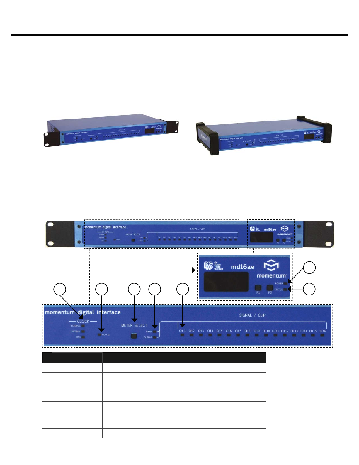
Front Panel
The front of the md16ae has a 2-button control panel and 16 input/output channels each with a
signal / clip LED indicator visible on the front panel.
The control panel includes a power LED, status LED, a 3-digit readout display and control
buttons (F1 and F2).
2-Button
Control Panel
LED
Descr
ip
t
i
on
1
P
ower
LED
Green = Di
g
ita
l
power OK
2
S
t
a
t
u
s LE
D
Green = Network connected; Red = Network faul
t
3
C
l
oc
k
Source In
d
icates se
l
ecte
d
c
l
oc
k
sourc
e
4
L
ocked Li
g
h
t
Red = unlocked; Green = locked
5
M
eter
S
elec
t
T
o
gg
les between input/output meterin
g
*
A
lso to
gg
les display between input/output start channel
6
Me
t
e
r
LED
In
d
icates in
p
ut
/
out
p
ut se
l
ecte
d
7
S
i
g
nal/Clip LE
D
Green = -40dB F.S. or above; Red= -3dB F.S. or abov
e
1
2
3 4 5 6 7
* Changing meter will
also change meter in
the software.
8
Momentum md16ae Manual
Overview
Chapter 1
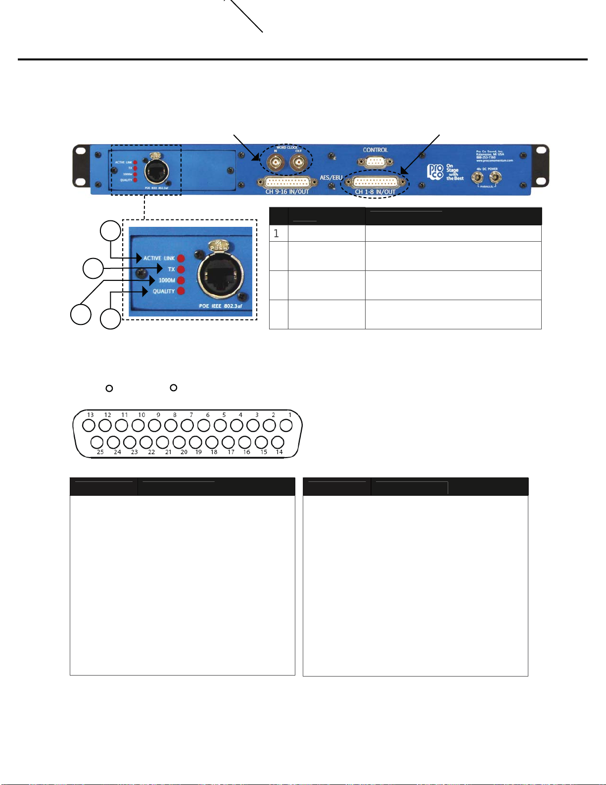
Rear Panel
The rear panel offers network status LEDs for monitoring the unit’s network connection.
LED
D
escr
ip
t
i
o
n
1
A
c
tiv
e
Lin
k
Sh
ows networ
k
activit
y
2
TX In
d
ic
a
tes th
a
t the mo
8
i
s
t
ransmittin
g
d
ata on t
h
e networ
k
3
1
000
mIn
d
ic
a
tes th
a
t the mo8 i
s
connected at one
g
i
g
abit
4
Qualit
y
Indicates an acceptable Ethernet
s
i
g
nal to noise rati
o
2
4
3
1
External Clock Connection See below for pin out diagram
Pin Out Diagram
DB2
5
P
i
nDescr
i
pt
i
on
1
2
3
4
5
6
7
8
9
10
11
12
13
D
i
g
ital Out 7/8
+
Groun
d
D
i
g
ital Out 5/6
-
D
i
g
ital Out 3/4
+
Groun
d
D
i
g
ital Out 1/2
-
D
i
g
ital In 7/8 +
Groun
d
D
i
g
ital In 5/6
-
D
i
g
ital In 3/4 +
Groun
d
D
i
g
ital In 1/2
-
No
C
o
nnec
t
DB2
5
P
in
D
escr
i
pt
i
o
n
14
15
1
6
1
7
18
1
9
20
21
22
23
2
4
2
5
D
i
g
ital Out 7/8
-
D
i
g
ita
l
Out 5
/
6 +
Gr
ou
n
d
D
i
g
ital Out 3/4
-
D
i
g
ita
l
Out 1
/
2 +
Gr
ou
n
d
D
i
g
ital In 7/8
-
D
i
g
ita
l
In 5
/
6 +
Gr
ou
n
d
D
i
g
ital In 3/4
-
D
i
g
ita
l
In 1
/
2 +
Gr
ou
n
d
Tascam / Digidesign Compatible
RR

9
Momentum md16ae Manual
One Spot or MUPS power supply ports
Ethernet port
P
o
w
e
r
Use only with the power supplies provided by Pro Co Sound.
Use the1. Pro Co One Spot power supply. It is shipped with the unit and allows the powering
of only one device. An alternative to the One Spot is the Multi Unit Power Supply (MUPS).
This power supply comes with three jumper cables that will allow up to four units to be linked
together and powered by one MUPS. The MUPS is a separate option and must be ordered
additionally.
Use a standard2. Gigabit IEEE 802.3af PoE network switch and power up through the
Ethernet cable. The POE switch must be capable of 15Watts per Ethernet port.
The Momentum output unit requires 48VDC power to operate. There are two ways to power the unit:
Use only 802.3af PoE power supplies.
OR
Chapter 2
Connection and Startup 2
10
Momentum md16ae Manual
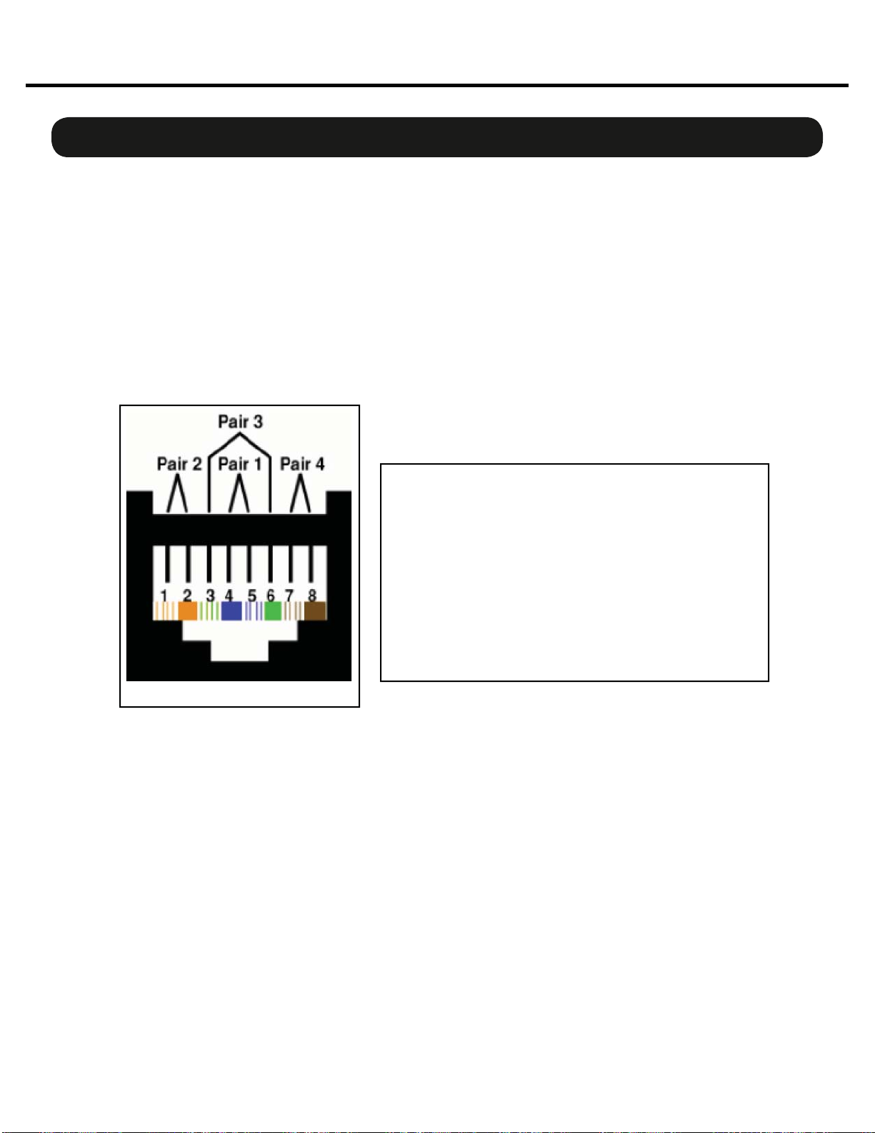
Pin T568B (female) Description
1 Orange/White
2 Orange
3 Green/White
4 Blue/Power
5 Blue/White
6 Green Receive
7 Brown/White
8 Brown Power
Bi-directional pair +A
Bi-directional pair - A
Bi-directional pair +B
Bi-directional pair +C
Bi-directional pair - C
Bi-directional pair - B
Bi-directional pair +D
Bi-directional pair - D
Copper Wiring
Use a minimum of• CAT5E or CAT6 network cable
Maximum cable length is 100 meters•
Connection and Setup
Chapter 2
N
etwor
k
Wi
r
i
n
g
Copper Connection
Use T568B or equivalent connectors when wiring your system. This view shows the color code as• viewed from the front of the female socket or the rear of the male connector.
Crossover wiring is not needed; the Momentum network interface compensates for unit-to-unit• connections.
Fiber Connection (Optional)
220 meter distance use 62.5/125um MMF 160MHz Km Cable
275 meter distance use 62.5/125um MMF 200MHz Km Cable
500 meter distance use 50/125um MMF 400MHz Km Cable
550 meter distance use 50/125um MMF 500MHz Km Cable
The Momentum Fiber option uses ST style connectors and operates at 850nm. The system is fully
IEEE 802.3z Gigabit Ethernet compliant. The following are performance based on the cable type:
T568B

11
Momentum md16ae Manual
Connection and Setup
Chapter 2
Network Confi
g
urations
The following are examples of network configurations. These samples show configurations using ana-
log inputs and outputs. Momentum digital input and outputs or DSP devices use the same methods for
network configuration.
Using the Momentum system, the network configuration possibilities are endless. For more information
on advanced configurations and support, visit www.procomomentum.com. For further support, con-
tact you local dealer or Pro Co technical support.
One to One Connection
CAT5E or CAT6
No crossover required
100 Meters
!
Direct Copper Connection
Optionally, Fiber and Copper may both be connected for redundancy.
mi8 Input
mo8 Output
Direct Fiber Connection
275 Meters using 62.5/125um MMF 200Mhz
550 Meters using 50/125um MMF 500Mhz
Cross Fiber Rx/Tx
Chn 001 must be present on the network at all
times. This unit will sync the network clock.

12
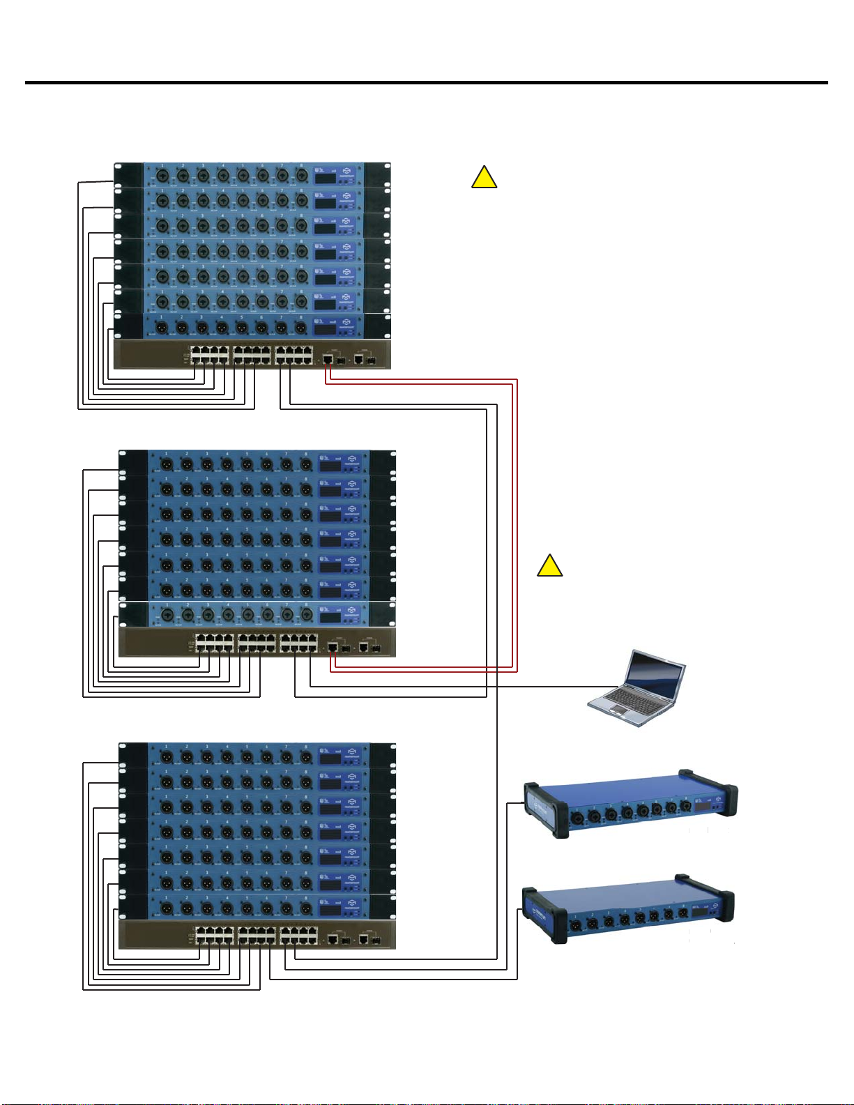
Momentum md16ae Manual
Connection and Setup
Chapter 2
48 x 8 Typical Snake System
md16ae Input/Output
Chi=001 Cho=001 Adr=001
Chi=017 Cho=001 Adr=002
Chn=033 Adr=003
Chn=041 Adr=004
mi8 Input
Chn=049 Adr=005
mi8 Input
Chn=057 Adr=006
mo8 Output
Chn=065 Adr=014
STAGE
Chi=OFF Cho=001 Adr=008
Chi=OFF Cho=017 Adr=009
Chi=OFF Cho=033 Adr=010
Chi=OFF Cho=049 Adr=011
mi8 Input
Chn=065 Adr=007
mo8 Output
FOH
CAT5E or CAT6
Optional Fiber Note:
Running both Fiber and CAT6 copper or two
CAT6 copper connections can provide a
redundant link between FOH and the Stage .
Ethernet Switches must be configured using
Spanning Tree Protocol
Managed
Ethernet Switch
Control Device
If running over 48 channels,you MUST
set the Ethernet port that is connected
to your control PC to multicast filtering.
Multicast MAC 01:15:AB:C6:00:00
(See Network Design White Papers)
!
Chn 001 must be present on the
network at all times. This unit will sync
the network clock.
!
Managed
Ethernet Switch
md16ae Input/Output
mi8 Input
mi8 Input
md16ae Input/Output
md16ae Input/Output
md16ae Input/Output
13
Momentum md16ae Manual
Connection and Setup
Chapter 2 Connection and Setup
48 x8 With Split Network System
mi8 Input
Chn=001 Adr=001
mi8 Input
Chn=009 Adr=002
mi8 Input
Chn=017 Adr=003
mi8 Input
Chn=025 Adr=004
mi8 Input
Chn=033 Adr=005
mi8 Input
Chn=041 Adr=006
mo8 Output
Chn=049 Adr=009
STAGE
mo8 Output
Chn=001 Adr=010
mo8 Output
Chn=009 Adr=011
Chn=017 Adr=012
Chn=025 Adr=013
Chn=033 Adr=014
Chn=041 Adr=015
mi8 Input
Chn=049 Adr=007
mo8 Output
mo8 Output
mo8 Output
mo8 Output
FOH
CAT5E or CAT6
Optional Fiber
Managed
Ethernet Switch
Control PC
If running over 48 channels,you MUST
set the Ethernet port that is connected
to your control PC to multicast filtering.
Multicast MAC 01:15:AB:C6:00:00
(See Network Design White Papers)
!
!
mo8 Output
Chn=001
mo8 Output
Chn=009
Chn=017
Chn=025
Chn=033
Chn=041
mo8 Output
mo8 Output
mo8 Output
mo8 Output
Additional Split
Chn=049
mo8 Output
mi8 Input
Chn=057 Adr=008
mo8 Output
Chn=057 Adr=023
Adr=016
Adr=017
Adr=018
Adr=019
Adr=020
Adr=021
Adr=022
Note:
Up to 256 inputs channels, and unlimited
outputs or DSPs can be added anywhere on the
network using this method.
Note:
Running both Fiber and CAT6 copper or two
CAT6 copper connections can provide a
redundant link between FOH and the Stage .
Ethernet Switches must be configured using
Spanning Tree Protocol.
Managed
Ethernet Switch
Managed
Ethernet Switch
Chn 001 must be present on the
network at all times. This unit will sync
the network clock.
mo8
O
ut
pu
Chn
=
05
7
A
mi8
Inp
ut
Chn 057
Ad

14
Momentum md16ae Manual
C
lock
C
on
fi
g
urations
Connection and Setup
Chapter 2 Connection and Setup
External Clock Source
EXTERNAL CLOCK SOURCE
md16ae
Chi=001 Adr=001
External Clock
Master Source
Additional md16ae’s on Network
Additional
Slave Device
!
Chn 001 must be present on the
network at all times. This unit will sync
the network clock.
md16ae
Chi=017 Adr=002
!
For a md16ae device to be set in
External clock source mode,it must be
set to transmit channels 1-16.
Additional
Slave Device
(not an md16ae)
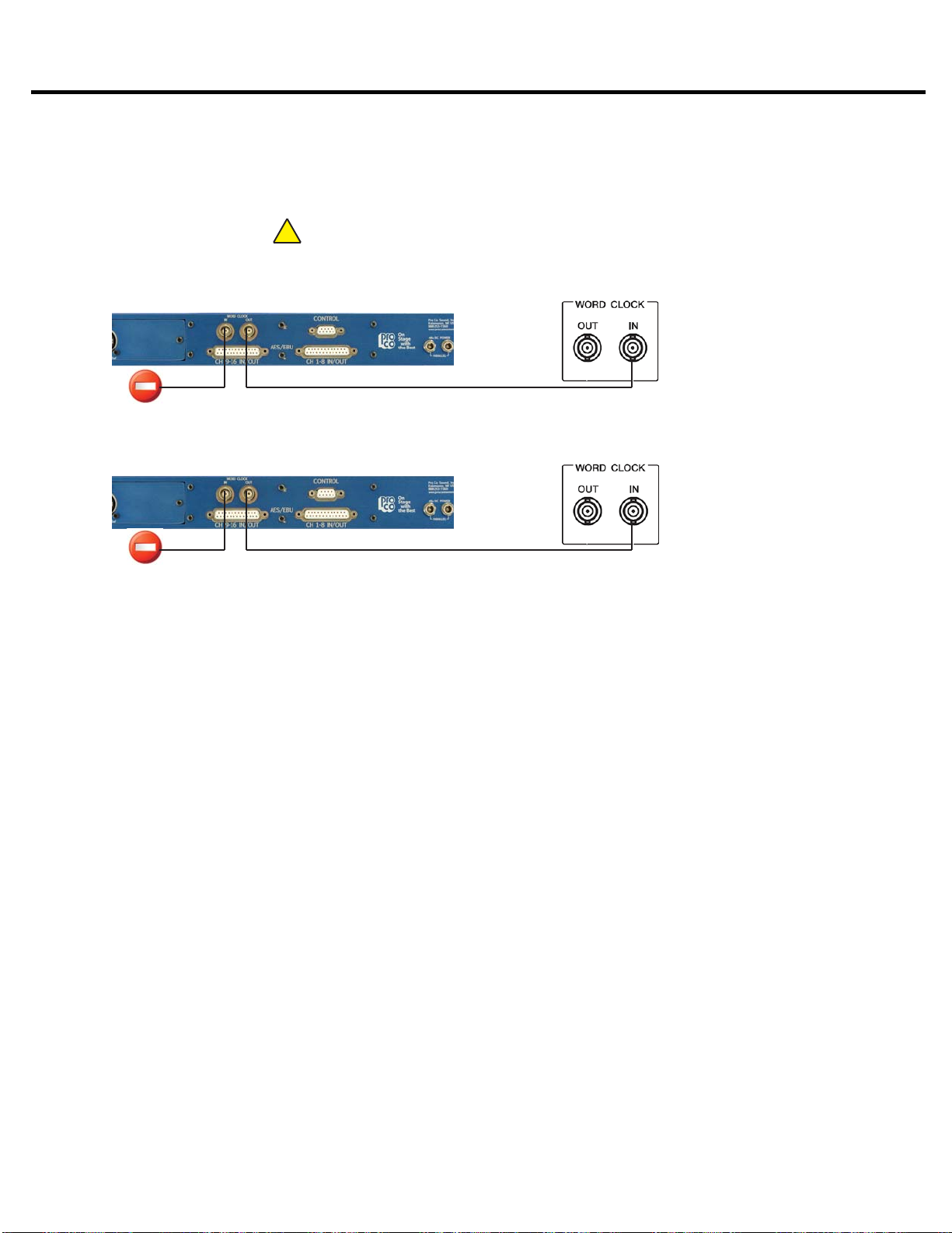
Overview of External Clock Source:
Please take note of the following instructions as the wiring of the md16ae differs from standard
clock wiring.
Only one md16ae can be connected to one external master clock and this device must transmit
channel 1. Other Momentum devices will then sync to this md16ae. The external clock connections
should not be daisy chained from one md16ae to another.
Set the md16ae clock source to• External using 2-button panel or PC software.
Connect clock source output to the word clock input of the md16ae.• Set clock to match the applicable Momentum sample rate. (48k or 96k)• When selected, the locked clock LED should be green.• An additional non-Momentum slave device can be connected to the word clock output.•
There are three available clock sources for the md16ae. In order for the clock source to be changed,
the device must be set to input start channel 1.
This will set the device as the Momentum Network
Clock Master
. If the device is set to any other start channel, it will only sync from the device on the
Momentum Network that is set to start channel 1. Clock (CL) adjustment will be UNAVAILABLE on
the front panel.
With the md16ae set to start channel 1, the three clock sources are External, Momentum and AES3.
External clock will sync the md16ae to the word clock BNC input (0.2 to 5Vp-p). With Momentum
clock selected the md16ae will use its internal clock. With AES3 selected the md16ae will use
channels 1 and 2 of the AES3 connection from which to sync. Any md16ae on the network displaying
a green locked light will output a valid clock signal from the word clock BNC out connector.
15
Momentum md16ae Manual
Connection and Setup
Chapter 2 Connection and Setup
Momentum Network Clock Source
MOMENTUM NETWORK CLOCK SOURCE
md16ae
Chi=001 Adr=001
External Slave
Device
NETWORK CLOCK MASTER
OR
md16ae
Chi=017 Adr=002
NETWORK CLOCK SLAVE
!
Chn 001 must be present on the
network at all times. This unit will sync
the network clock.
Additional
Slave Device
(not an md16ae)
Overview of Momentum Network Clock Source:
If the• Momentum Network clock is selected and transmitting channel 1, this unit is the clock
master.
If it is set to transmit any other channel, the unit will sync to the Momentum device that has• been set to transmit channel 1.
Set clock to match the applicable Momentum sample rate. (48k or 96k)• When selected, the locked clock LED should be green.• An additional non-Momentum slave device can be connected to the word clock output.•

16
Momentum md16ae Manual
Connection and Setup
Chapter 2 Connection and Setup
AES3 Clock Source
AES3 CLOCK SOURCE
md16ae
Chi=001 Adr=001
External Clock
Master Source
Additional md16ae’s on Network
Additional
Slave Device
!
Chn 001 must be present on the
network at all times. This unit will sync
the network clock.
md16ae
Chi=017 Adr=002
Additional
Slave Device
(not an md16ae)
AES Channels 1 and 2 provides the clock source for the md16ae
!
For a md16ae device to be set in AES3
clock source mode,it must be set to
transmit channels 1-16.
Overview of AES3 Clock Source:
Only one md16ae can be set to sync to the AES3 clock source and this device must transmit
channel 1. All other Momentum devices will then sync to this device.
With AES3 clock source selected, the md16ae will sync to AES3 channels 1 & 2.• Set clock to match the applicable Momentum sample rate. (48k or 96k)• When selected, the locked clock LED should be green.• An additional slave device can be connected to the word clock output.•

17
Momentum md16ae Manual
Connection and Setup
Chapter 2
S
etu
p
Network Clock Sync
PLEASE TAKE NOTE OF THE FOLLOWING:
The Momentum network MUST have ONE mi8 or md16ae that is assigned CHANNEL 1. This as-
signment is used to synchronize all of the device clocks on the network. Without this assignment, the
system clock will not sync and audio ‘clicks’ will be heard.
The md16ae unit includes a control panel with an LED display and two push buttons (F1 and
F2). The device can be configured through a series of key strokes using F1 and F2. The control
panel will only control the local device and cannot change other units via the network.
Using the Control Panel
F1 - Mode Edit / Decrease Value
F2 - Mode Select / Increase Value
Display
Status Indicator
Power Indicator
Button
/
LE
D
Descr
ip
t
i
o
n
F1 Mode
S
elect
:
F1 activates the edit mode within a
p
articular function.
F2 Mode
S
elect
:
F2
g
enerally selects which function to edit.
P
o
w
e
r In
d
i
ca
t
o
r
:
T
he
p
ower indicator shows that a
p
ower source is connected to the
Momentum units. The LED is connected to the di
g
ital power source.
All other
p
ower sources in the s
y
stem can be monitored via the PC
s
oftware.
S
tatus Indicator
:
T
he st
a
t
u
s in
d
ic
a
t
o
r is
a
b
i-c
o
l
o
r LED.
G
REEN
i
n
d
ic
a
tes
a
ll M
o
men-
tum Network connections have been found and the network is run
-
nin
g
.
RED
i
ndicates there are one of two problems;
1
)
A Ethernet link is not established or is not connected.
2
)
the audio s
y
nc
p
acket
(
channel 1
)
is not found.

18
Momentum md16ae Manual
This function sequentially routes all sixteen input/output channels to match the corresponding
devices. The start channel route is primarily used during the initial set up of the system. Channels
are set in grouping of sixteen i.e. 1-16, 17-32, 33-48 etc. If “- - -” shows on the display, it indicates
that one or any of the channels is out of sequence. To individually route channels use the “rou”
function. See page 17 for details on the “rou” function.
Start Channel Route for Input and Outputs
Connection and Setup
Chapter 2
An IP address will need to be set only if the Momentum
network will be controlled with a PC or external controller.
The IP address defaults to 192.168.1.1. When in the idle
menu state, pressing the F1 button will flash the current ad-
dress. The number shown is the LSB of the IP address
(192.168.1.[LSB]). If the network is to be controlled with
a PC, each Momentum unit will need a unique IP address. All
IPs need to be set manually on the individual unit.
It is best practice to keep the input unit’s IP address sequential with its channel. In other words,
Chn 001-008 would be Adr 001 and Chn 009-016 would be Adr 002 and so on.
ALL DEVICES in the network must be set at the same sample rate of either 48k or 96k.
IP Address
Sample Rate
THE FOLLOWING FRONT PANEL SETTINGS MUST BE CONFIGURED PRIOR TO USING MOMENTUM.
The IP setting is required only if the unit will be controlled with a PC or external controller.
A detailed description of control functions can be found in chapter 3, pages 16-18.
Setting Device Before Use
The md16ae must be set to input start channel 1 in order to access the clocking function. Use the
F1 soft button to scroll between the three clocking options; external (coax connection), Momentum
(Internal Network clock) and AES3 (Input channel 1 of AES3). External clocks can only be at a
sample rate of 48k or 96k to match the Momentum capability.
Clocking
- Channel Input - Channel Output

19
Momentum md16ae Manual
This chapter describes each of the control panel functions and how to access them to make changes to
your network. Changes are made using the F1 and F2 keys.
Display
F2 - Function Select / Increase Value
The settings of the Momentum units are accessible through a series of key strokes between F1 and F2.
In general, F2 selects which function to edit, and F1 activates the edit mode within that function. Holding
both F1 and F2 executes edit and exits edit mode.
The flow chart below displays each of the controlling F1 and F2 functions. Descriptions of each functions
follow in a guide on pages 16 and 17.
F1 - Function Edit / Decrease Value
F1
a
n
d
F2 F
u
n
c
ti
o
n
s
Chapter 3
Control Panel Functions 3
F2
[rou]
Route
F2
[Adr]
IP
Address
F2
[Sr]
Sample
Rate
F1
[Adr]
IP
Address
Display
F1 F2
F2
[Chi]
Channel
Input
F2
[Cho]
Channel
Output
F2
[Cl]
Clock
Setup
* Clock not visible if not transmitting channel 1.

20
Momentum md16ae Manual
Individual Channel Route
IP Address View
Control Panel Functions
Chapter 3
Description of Functions
Pressing F1 will flash the IP address of a unit.1.
Toggle F2 to until “rou” is displayed.1. Tap F1 to activate “rou” edit mode.2. Toggle F1 to scroll channels. Toggle F2 to select a channel.3. Tap F1 to decrease value. Tap F2 to increase value.4. Press and hold F1 and F2 to execute and save the change.5. Return to selecting channels or exit by allowing display to time out.6.
To return to the beginning of the menu, allow the display to time out. When the display times out and
when the unit is at idle, the start channel number of the unit’s channel bank will be displayed.
Please note:
The functions in the step by step guide are presented in the same order as the functions1. on the unit’s menu structure.
In order to edit a channel, the user must first scroll to the function in need of editing, select2. the appropriate channel and make the edit.
Note about Routing:
The number shown on the display will be the first of eight consecutive numbers.• When an individual channel is given new routing number that is out of se-• quence, the display will show “- - -”. This display makes it easy to identify which
md16ae unit has channel/channels that are out of sequence.
To put channels back into sequential order, toggle F2 to “Cho” and assign that• sequence a new start channel.
Input Channel Start Route (Off or 1-241)
Toggle F2 until “Chi” is displayed.1. Tap F1 to activate “Chi” edit mode.2. Tap F1 to decrease value. Press F2 in increase value. Channels increase/decrease by eight.3. (Off disables all inputs)
Press and hold F1 and F2 to execute and save the change.4.
Table of contents


