Akai APC MIX User manual

SPECIFICATIONS
Knobs
KnobsKnobs
Knobs
24
24 24
24
270° assignable knobs
Banks accessible via
Bank Left/Right
Bank Left/Right Bank Left/Right
Bank Left/Right
buttons
Faders
FadersFaders
Faders
8
8 8
8
30mm assignable faders
1
1 1
1
30mm assignable master fader
Banks accessible via
Bank Left/Right
Bank Left/Right Bank Left/Right
Bank Left/Right
buttons
Buttons
ButtonsButtons
Buttons
8
8 8
8
assignable mute buttons, amber-backlit with solo functionality
1
1 1
1
assignable solo button to change functionality of 8
Mute
Mute Mute
Mute
buttons
8
8 8
8
assignable record-arm buttons, red-backlit
2
2 2
2
assignable bank buttons left, right
1 Send All
1 Send All 1 Send All
1 Send All
button
Connections
ConnectionsConnections
Connections
1
1 1
1
USB port
1 Kensington lock s
1 Kensington lock s1 Kensington lock s
1 Kensington lock slot
lotlot
lot
Power
PowerPower
Power
USB-bus-powered
Dimensions
DimensionsDimensions
Dimensions
(width x depth x height)
9.4” x 7.9” x 1.2”
23.9 cm x 20.1 cm x 3.0 cm
Weight
WeightWeight
Weight
1.5 lbs.
0.7 kg
SERVICE MANUAL
MODEL:
APC M
IX

DISASSEMBLY PROCEDURES
1.
DISASSEMBLE THE BOTTOM PANEL.
(A) REMOVE 24 PCS KNOB AND 9 PCS SLIDER VR CAP FROM THE TOP PANEL.
(B) REMOVE 10 SCREWS FROM THE BOTTOM PANEL.
(Fig1)
2.
DISASSEMBLE THE MAIN PCB ASSEMBLY.
(A)REMOVE 5 SCREWS FROM THE MAIN PCB ASSEMBLY.
(Fig2)

PACKING DIAGRAM
(US)

EXPLODE DIAGRAM
(US)
EQUENCIAL NO EXPLODE DIAGRAM WILL BE MARKED ON REF.COLUMM OF BOM LIST

ADA7AKA01 BOM
LEVEL
P/N DESCRIPTION QTY
REF
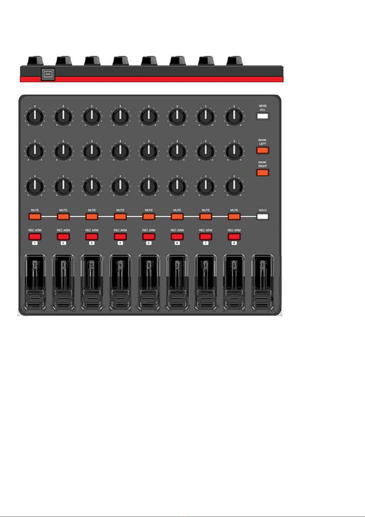
0 ADA7AKA01 APCMIX USB USA 0
1 BAAR-0137 Rubber Feet Pad 4 8
1 CA040210002 USB 2.0 Cable 1m A/B Type Black Core 1
1 GEAKA17 Ableton Card 1
1 LAC22AKA379 Serial Number Label 0.25
1 LAC22AKA42 Sticker S/N Ableton 1
1 LAC57AKA411 Label 1
1 LAC62AKA380 Bar Code Label(CODE39) 0.25
1 LAC62AKA381 Bar Code Label(GTIN14) 0.25
1 LAC67MAR681 Label(Circle Limpid) 1
1 LAC67YAH261 Label φ8mm Green 1
1 NM1501811 Velvet Carpet 9 3
1 PADA7AKA01 Packing Assembly 1
2 AL7-51-0226-M Safety Manual 1
2 CGADA7310AKA01 Gift Box 1
2 CTADA7513AKA01 Shipping Carton 0.25
2 GEAKA20 Generic Card 1
2 OPADA7AKA01 Quick Start User's Manual 1
2 PE230190402B07 Poly Bag 230*370mm 1
2 PLADA701 Poly Foam(L) 1
2 PLADA702 Poly Foam(R) 1
2 SD30026010 Soft Sheet Bag 1
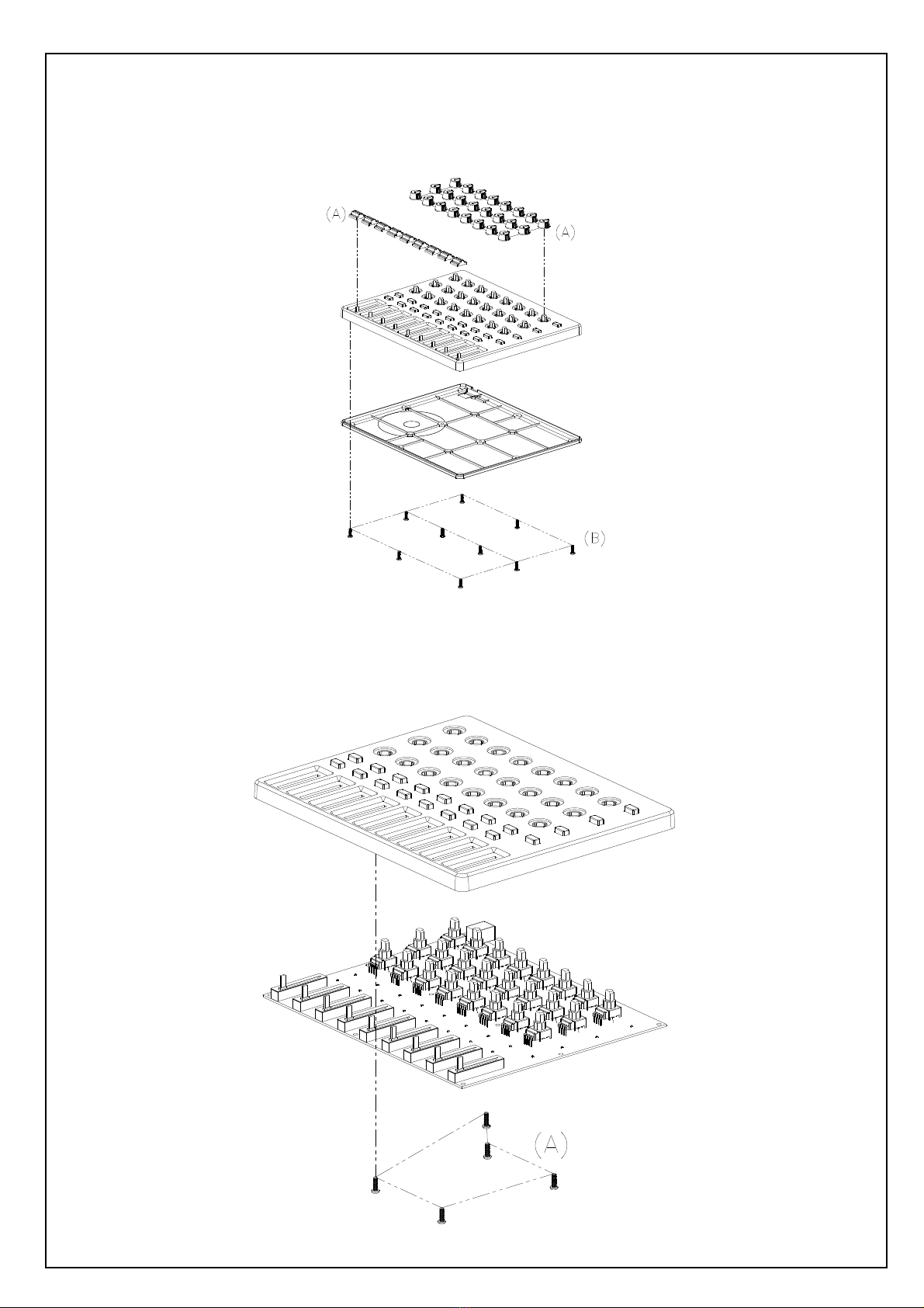
1 PT1510618901 Slide VR Cap(Paint White) 9 1
1 PT153004701 Top Housing(Printing-Painting) 1 2
2 PT1530047 Top Housing 1
1 PT1530339 Bottom Housing 1 6
1 RU1510636 Rubber Knob 1 10
1 RU1510637 Rubber Knob 1 4
1 SC0308PBBI Screw M3X8 PBB Tapping 5 11
1 SC0310PBBI SCREW M3X10 PPB TAPPING 10
7
1 TWPC14A02101 Main pcb Assembly 1 5
2 AL2-51-4403 Transistor 2N4403 PNP SOT-23 1 Q1
2 AL2-52-5242 Diode MMBZ5242B 1 D22
2 AL2-54-6306 Mosfet FDC6306P P-CH SSOT-6 1 Q2
2 AL2-61-7223 IC NJU7223DL1-33 3.3V TO-252 1 U2
2 AL2-63-0541 IC SN74AHCT541DWR SOIC-20 1 U9
2 AL2-73-4051 IC74HC4051 Single 8-Chan Mux 16P Soic 4 U3~6
2 AL4-08-0402 Con USB 4-Pin Female PC-MNT Horizontal 1 USB1
2 CS102K5003X7R CCAP SMD 1nF/50V 10% 0603 X7R 38
C31~39,41~48,51~58,61~68,103~107
2 CS103K5003X7R CCAP SMD 0.01uF/50V 10% 0603 X7R 33
C7,14,23,40,72~100
2 CS104K5003X7R CCAP SMD 0.1uF/50V 10% 0603 X7R 19
C1~3,5,6,8~12,20,22,24,27,28,50,60
C70,102
2 CS105K2505X7R CCAP SMD 1uF/25V 10% 0805 X7R 1 C16
2 CS330J5003NPO CCAP SMD 33pF/50V 5% 0603 NPO 2 C25,26
2 CS471J5003NPO CCAP SMD 470pF/50V 5% 0603 NPO 1 C71
2 DIEN1N4148WSM Diode SMD 20
D2~21
2 ECS10710D Capacitor Electrolytic 100UF 10V SMD-D 1 C13
2 ECS22616B Capacitor Electrolytic 22uF/16V B type 2 C4,101

SMD
2 ECS47525B Ecap 4.7uF/25V 4*5.4mm SMD 4 C30,49,59,69
2 IC74HC595 Integrated Circuit 2 U7,8
2 ICUSBLC62SC6 IC USBLC62SC6 SOT-23-6L 1 D1
2 ICYH103M14 IC(STM32F072C8T6+Program V1.00) LQFP-48 1 U1
3 ICSTM32F072C8T6 IC STM32F072C8T6 LQFP-48 1 (U1)
2 LDKPT-1608SURCK Liquid-emitting Diode Red SMD 0603 8 LD9~16
angle 120°
2 LDKPT-1608SYCK Liquid-emitting Diode Yellow SMD 0603 10
LD1~8,17,18
angle 120°
2 PC14A021 Main PCB 2Layer 225x203mm 1.6T ENIG 1 -
2 RS000004J06 RES 0Ω5% SMD 1206 1 R13
2 RS000008J05 RES 0Ω5% SMD 0805 1 R1
2 RS001K08F05 RES 1K 1% SMD 0805 3 R25,26,28
2 RS001M10F03 RES 1M 1% SMD 0603 1 R16
2 RS002710F03 RES 27Ω1% SMD 0603 2 R20,21
2 RS010010F03 RES 100Ω1% SMD 0603 2 R15,24
2 RS010K10F03 RES 10K 1% SMD 0603 9 R4~11,62
2 RS015K10F03 RES 15K 1% SMD 0603 1 R22
2 RS01K510F03 RES 1.5K 1% SMD 0603 1 R18
2 RS022010F03 RES 220Ω1% SMD 0603 18
R41~58
2 RS051010F03 RES 510Ω1% SMD 0603 1 R2
2 RS820K08F05 RES 820K 1% SMD 0805 1 R27
2 TE591271001 Pin Header 180°Pitch:1.27mm Dual Row 1 J1
5Pin*2 SMD
2 VRR10302022 Potentiometer Rotary Volume:10K SB Shaft 24
VR1~24
Length:20mm Single Unit
2 VRS10303009 Potentiometer Slide Volume:10K SB Travel 9 VR25~33
30mm Lever Length:10mm Single Unit
1 TWPT15106136 Indicate Knob 24
9
2 PT15106135 Indicate Line 24
2 PT15106136 Knob bodg 24

▓
Appearance models

▓
Testing software installation
If you have installed, you can skip this Midi ProjectInstaller installation
STEP 1
STEP 1STEP 1
STEP 1
Please be ready "Midi ProjectInstaller - v2.0.0.33 (noscript) .exe" (Please attention to version update status),
hen start the software installation.(MidiProjectInstaller - v2.0.0.33(noscript).exe for example)
If the computer OS is 64bit, hen install MidiProjectInstaller - v2.0.0.33(noscript)-x64.exe
STEP 2
STEP 2STEP 2
STEP 2
First, when you see the following window, press Next

STEP 3
STEP 3STEP 3
STEP 3
When you see the following window, press the I Agree
STEP 4
STEP 4STEP 4
STEP 4
First, when you see the following window, press Next

STEP 5
STEP 5STEP 5
STEP 5
First, when you see the following window, press Next
STEP 6
STEP 6STEP 6
STEP 6
First, when you see the following window, press Install

STEP 7
STEP 7STEP 7
STEP 7
Wait for the installation is complete
STEP 8
STEP 8STEP 8
STEP 8
When you see the following window, press Finish, installed complete.

STEP 9
STEP 9STEP 9
STEP 9
If you have checked Run Midi Project in STEP8, then you will see the following window, please turn off
this window.
STEP 10
STEP 10STEP 10
STEP 10
Please ready "ADA7 Script Low Resolution Installer V0.1_2015.01.26.exe" (Please attention to
version update status), then Begin software installation.

STEP 11
STEP 11STEP 11
STEP 11
First, when you see the following window, press Next
STEP
STEP STEP
STEP 12
1212
12
When you see the following window, press the I Agree

STEP 13
STEP 13STEP 13
STEP 13
When you see the following window, press Install
STEP 14
STEP 14STEP 14
STEP 14
When you see the following window, press Finish, installed complete.

▓
▓▓
▓測試軟體操作方法
測試軟體操作方法測試軟體操作方法
測試軟體操作方法
Note:
During the test,
The red figure indicates that no test;Yellow, green shows they in test;Blue shows the
test is correct.
Because during the test is pressed SEND ALL buttom will be calibrated and stored value for Knob and
fader,Therefore, you must first make knob, fader then the buttom test after test.
Execution Knob and fader test,No matter how many numerical display, are required to rotate to the
end.
STEP 1
STEP 1STEP 1
STEP 1
Hold down the SEND ALL button, and then insert the USB cable, allowing the machine to enter the
test mode . (If the SEND ALL continue to hold, the MUTE 1 ~ MUTE 8 buttons LED displays the
current version of the machine)
STEP 2
STEP 2STEP 2
STEP 2
Run application software “Midi Device” on the PC
Device selection ADA7, press Create

STEP 3
STEP 3STEP 3
STEP 3
The right of the window that will appear in the test screen ADA7

STEP 4
Click Connect,
Version appears underneath the machine Edition,T The right of the window into the red
zone to be tested.
Confirm the connection, the version is correct,Then press Run, begin testing.
STEP 5
STEP 5STEP 5
STEP 5 Knob Test
Red: Not tested.
Green: Rotary to minimum 0
Yellow: Rotary to the maximum 127
Blue: the test is completed.
STEP 6
STEP 6 STEP 6
STEP 6 - Fader Test
The same test methods and Knob
Red: Not tested.
Green: Slide to minimum 0
Yellow: Slide to the maximum 127
Blue: the test is completed.

STEP 7
STEP 7STEP 7
STEP 7 – Button, LED test
Press the button the software will show green, blue will not pressed
Press the button, the corresponding LED will light up
STEP 8
STEP 8STEP 8
STEP 8
Completion of the above test, the test screen below will appear Complete

1
1
2
2
3
3
4
4
D D
C C
B B
A A
Check REV Description
Title:
SizeA4 Number Revision
Date :
File Name: Sheet of
Design By :
DATEDesignApproval
2015/2/11 0
PC14A021
ADA7 MAIN PCB-MCU
\\ADA7.prj
1 4
Hungchi Lee
D+3.3V
NRST
DGND
DGND
DGND
USB RST
VR+3.3V
DGND
DM
DP
DM
DP DGND
DGND
LED+5V
VR-A
VR-B
VR-C
VR-D
VR-MASTER
VR-SEL2
VR-SEL1
VR-SEL0
KEY_D0
KEY_D1
KEY_D2
KEY_D3
KEY_D4
KEY_D5
KEY_D6
KEY_D7
KEY_SCAN0
KEY_SCAN1
KEY_SCAN2
LED-OE
LED-CLK
LED-RC
LED-DO
LED-BANKL
LED-BANKR
DGND
D+3.3V
USB RST
DGND
DGND
DGND
+5VUNREG
VR+3.3V
USB_DM
USB_DP
DGND
USB_DM
USB_DP
SWD
SWC
Not Fitted
C8 0.1uF
R16 1M
AL4-08-0402
Vbus 1
D- 2
D+ 3
GND 4
UGND
5
UGND
6
USB1
B-TYPE 1.1
1uF
C16 R25
1K
0.1uF
C22
R26
1K
Q1
MBT4403
1 3
D22
12V
3
42 DS
G
FDC6306P
Q2B
R27
820K
1
65 DS
G
FDC6306P
Q2A
0.1uF
C27
R28
1K
NJU7223DL1-33
OUT 1
IN
2
3
GND
U2
0.1uF
C3 C4
22uF/16V 0.1uF
C1
0.1uF
C5
R1
0
R13
0-1206
1
2
34
5
6
ICUSBLC62SC6
D1
R20 27
R21 27
33pF
C26
33pF
C25
R18
1.5K 1%
R22
15K 1%
30pF
C15
30pF
C21 C10 0.1uF
C9 0.1uF
C2 0.1uF
R15 100
C28
0.1uF
R2 510
C20 0.1uF
VBAT
1
PC13
2
PC14/OSC32_IN
3
PC15/OSC32_OUT
4
PF0/OSC_IN
5
PF1/OSC_OUT
6
NRST
7
VSSA
8
VDDA
9
PA0/ADC_IN0
10
PA1/ADC_IN1
11
PA2/ADC_IN2
12
PA3/ADC_IN3
13
PA4/ADC_IN4
14
PA5/ADC_IN5
15
PA6/ADC_IN6
16
PA7/ADC_IN7
17
PB0/ADC_IN8
18
PB1/ADC_IN9
19
PB2
20
PB10
21
PB11
22
VSS
23
VDD
24 PB12/SPI2_NSS 25
PB13/PSI2_SCK 26
PB14/SPI2_MISO 27
PB15/SPI2_MOSI 28
PA8 29
PA9/USART1_TX 30
PA10/USART1_RX 31
PA11/USB_DM 32
PA12/USB_DP 33
PA13 34
VSS 35
VDDIO2 36
PA14/USART2_TX 37
PA15/USART2_RX 38
PB3 39
PB4 40
PB5 41
PB6 42
PB7 43
BOOT0 44
PB8/I2C1_SCL 45
PB9/I2C1_SDA 46
VSS 47
VDD 48
U1
ICSTM32F072C8T6
ICE
Connect
Not Fitted
1
32
4
X1
8MHz
R61
1M
R60 0
100uF, 10V
C13
R62 10K
1000pF C103
1000pF C104
1000pF C105
1000pF C106
1000pF C107
DGND
C101
22uF/16V
0.1uFC102
D+3.3V
SWD
SWC
NRST
DGND
1
2
3
4
5
6
7
8
9
10
J1
Table of contents
Other Akai Recording Equipment manuals

Akai
Akai MPC 2500 Installation and operating instructions

Akai
Akai APC40MKII User manual

Akai
Akai EIE Pro User manual

Akai
Akai s2000 User manual

Akai
Akai MPC Live User manual

Akai
Akai AW10 User manual

Akai
Akai DPS24 User manual

Akai
Akai LPD8 mk2 User manual

Akai
Akai MPC2000 User manual

Akai
Akai MPD18 User manual