manuals.online logo
Brands
  1. Home
  2. •
  3. Brands
  4. •
  5. Pro
  6. •
  7. Thermostat
  8. •
  9. Pro T701 User manual

Pro T701 User manual

FAN
ON AUTO
SYSTEM
COOL OFF HEAT
Installation Manual
Thermostat Application Guide
Description
Gas or Oil Heat
Electric Furnace
Heat Pump (No Aux. or Emergency Heat)
Heat Pump (With Aux. or Emergency Heat)
Multi-Stage Systems
Heat Only Systems
Heat Only Systems - Floor or Wall Furnace
Cool Only
Millivolt
Yes
Yes
Yes
No
No
Yes
Yes
Yes
Yes
Power Type
Battery Power
Hardwire (Common Wire)
Hardwire (Common Wire) with
Battery Backup
Table of Contents
Specications
Installation Tips
Thermostat Quick Reference
Wiring
Wiring Diagrams
Technician Setup
Page
A trained, experienced
technician must install this
product.
Carefully read these
instructions. You could damage
this product or cause a
hazardous condition if you fail
to follow these instructions.
Una version en español de este
manual se puede descargar en
la pagina web de la compañia.
Rev. 1809
U.S. Registered Trademark. Patents pending
Copyright 2018 All Rights Reserved.
Specications
The display range of temperature ... 41˚F to 95˚F (5˚C to 35˚C)
The control range of temperature.... 44˚F to 90˚F (7˚C to 32˚C)
Swing (cycle rate or dierential) ...... Heating is adjustable from 0.2˚ to 2.0˚
Cooling is adjustable from 0.2˚ to 2.0˚
Power source ...........................................18 to 30 VAC, NEC Class II, 50/60 Hz
for hardwire
Battery power from 2 AA Alkaline
batteries
Operating ambient ............................... 32˚F to +105˚F (0˚C to +41˚C)
Operating humidity .............................. 90% non-condensing maximum
Dimensions of thermostat ................. 4.7”W x 4.4”H x 0.8”D
Mount Thermostat
Align the 4 tabs on the subbase with
corresponding slots on the back of the
thermostat, then push gently until the
thermostat snaps in place.
Battery Installation
Battery installation is recommended even if thermostat is hardwired
(C terminal connected). When thermostat is hardwired and batteries
are installed, the thermostat will activate a compressor delay of 5
minutes when the thermostat detects a power outage from the
hardwired power supply.
Important:
High quality alkaline batteries are recommended.
Rechargeable batteries or low quality batteries
do not guarantee a 1-year life span.
Insert 2 AA
Alkaline batteries
(included). High
quality alkaline
batteries are
recommended.
Simple
operating
instructions
are found
on the back
of the
battery
door.
Gas or Electric Setup
Fan Operation Switch
Installation Tips
2-3
4
5
6
7-8
1
Installation Tips Thermostat Quick Reference
Getting to know your thermostat
Glow in the dark light button
Fan switch
System switch
Easy change battery door
Temperature setpoint buttons
LCD
The low battery indicator is displayed when the
AA battery power is low. If the user fails to
replace the battery within 21 days, the screen
will only show the low battery indicator but
maintain all functionality. If the user fails to
replace the batteries after an additional 21 days
(days 22-42 since rst“low battery” display) the
setpoints will change to 55˚F (Heating) and 85˚F
(Cooling). If the user adjusts the setpoint away
from either of these, it will hold for 4 hours
then return to either 55˚F or 85˚F. After day 63
the batteries must be replaced immediately to
avoid freezing or overheating because the
thermostat will shut the unit o until the
batteries are changed.
Important
Removing The Private
Label Badge
About The Badge
All of our thermostats use the same universal magnetic badge. Visit the
company website to learn more about our free private label program.
=
88
Room Temperature
o88
Set At
C
COOL ON
HEAT ON
F
LOW
Displays the
selected setpoint
temperature.
System Operation
Indicators:
The COOL ON, HEAT
ON or icon will
display when the
COOL, HEAT, or
(fan) is on.
NOTE: The
compressor
delay feature is active
if these icons are
ashing. The
compressor will not
turn on until the 5
minute delay has
elapsed.
Low Battery Indicator:
Replace batteries when
indicator is shown.
Indicates the current
room temperature.
Magnet in door
Subbase Installation
The thermostat should be installed approximately 4 to 5 feet above the
oor. Select an area with average temperature and good air circulation.
• Close to hot or cold air ducts
• That are in direct sunlight
• With an outside wall behind
the thermostat
• In areas that do not require
conditioning
• Where there are dead spots
or drafts
(in corners or behind doors)
• Where there might be
concealed chimneys or
pipes
Wall Locations
Vertical Mount
Horizontal Mount
For vertical mount put one screw on the top
and one screw on the bottom.
For horizontal mount put one screw on the
left and one screw on the right.
All of our products are mercury free.
However, if the product you are
replacing contains mercury, dispose of
it properly. Your local waste
management authority can give you
instructions on recycling and proper
disposal.
Pick an installation location that is easy for
the user to access. The temperature of the
location should be representative of the
building.
Installation Tip
Mercury Notice
Do not install
thermostat in locations:
Failure to disconnect the power before
beginning to install this product can
cause electrical shock or equipment
damage.
Installation Tip:
Electrical Hazard
Use the bevel on lower ridge
Gas: For systems that control the fan
during a call for heat, put the fan
operation switch to the GAS position.
Electric: For systems that do not
control the fan during a call for heat,
put the fan operation switch tothe
ELECTRIC position.
T701
Pro1 Technologies
Toll Free: 888-776-1427
Web: www.pro1iaq.com
Hours of Operation: M-F 9AM - 6PM Eastern
P.O. Box 3377
Springeld, MO 65808-3377
FAN
ON AUTO
SYSTEM
COOL OFF HEAT
Wiring
Caution:
Electrical Hazard
All components of the control
system and the thermostat
installation must conform to
Class II circuits per the NEC Code.
Warning:
Do not overtighten terminal
block screws, as this can
damage the terminal block.
A damaged terminal block
can keep the thermostat
from tting on the subbase
correctly or cause system
operation issues.
Installation Tip
Max Torque = 6in-lbs.
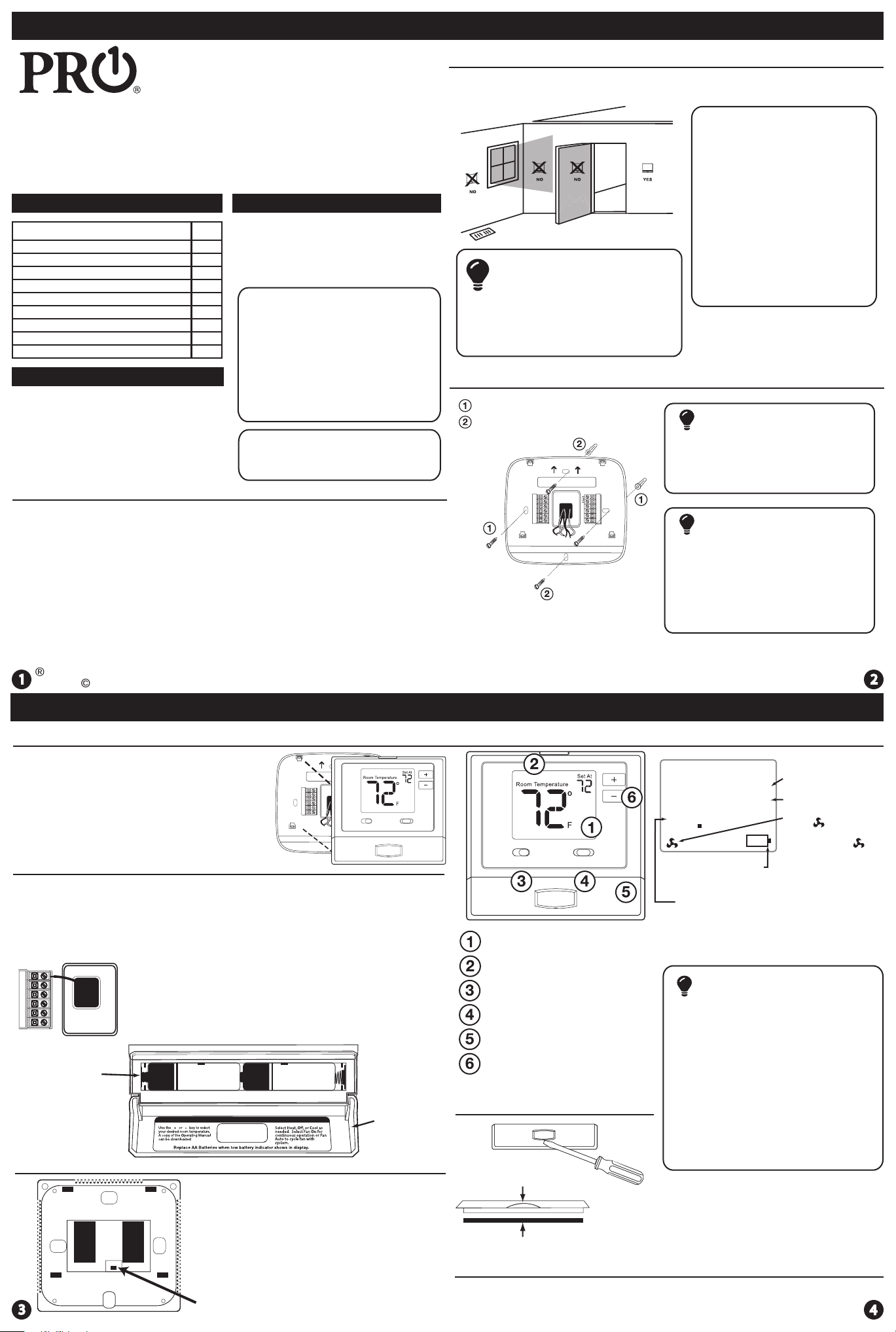
Wiring
If you are replacing a thermostat,
make note of the terminal
connections on the thermostat that
is being replaced. In some cases
the wiring connections will not be
color coded. For example, the
green wire may not be connected
to the Gterminal.
Loosen the terminal block screws.
Insert wires then retighten terminal
block screws.
Place nonammable insulation into
wall opening to prevent drafts.
1.
2.
3.
Terminal Designations
C
OHeat pump changeover valve
energized in cooling
Heat pump changeover valve
energized in heating
WHeat relay
RH Transformer power
for heating
RC Transformer power
for cooling
GFan relay
YCompressor relay
Wiring Tips
RH & RC Terminals
For single transformer systems, leave the
jumper wire in place between RH and RC.
Remove jumper wire for two transformer
systems.
Heat Pump Systems
If wiring to a heat pump, use a small piece
of wire (not supplied) to connect
terminals W and Y.
(With NO AUX or
Emergency Heat)
C Terminal
The C (common wire) terminal does
not have to be connected when the
thermostat is powered by batteries.
Wire Specications
Use shielded or non-shielded 18-22
gauge thermostat wire.
Failure to disconnect the power
before beginning to install this
product can cause electrical shock
or equipment damage.
B
Common wire from secondary side of
cooling system transformer
Wiring Diagrams
Power supply
Factory-installed jumper. Remove only when installing on 2-transformer systems
Use either O or B terminals for changeover valve
Use a small piece of wire (not supplied) to connect W and Y terminals
Set fan operation switch to Electric
Optional 24 VAC common connection when thermostat is used in battery power mode
Typical 1H/1C System: 1 Transformer Typical 1H/1C System: 2 Transformer
COMPRESSOR
RELAY
HEAT RELAY
FAN RELAY
> Typical 1H/1C Heat Pump System Typical Heat-Only System
Typical Heat Only System With Fan Typical Cool-Only System
COMPRESSOR
RELAY
HEAT RELAY
FAN RELAY
RC
RH
Y
C
W
G
C
R
L2
L1(HOT) RC
RH
Y
C
W
G
L2
L1(HOT)
REMOVE JUMPER C
R
COMPRESSOR
RELAY
FAN RELAY
COOL CHANGE
OVER VALVE
HEAT CHANGE
OVER VALVE
OB
C
R
L2
L1(HOT)
RC
RH
Y
C
W
GHEAT RELAY
RC
RH
Y
C
W
G
C
R
L2
L1(HOT)
FAN RELAY
HEAT RELAY
RC
RH
Y
C
W
G
C
R
L2
L1(HOT)
FAN RELAY
COMPRESSOR
RELAY
C
R
L2
L1(HOT)
RC
RH
Y
C
W
G
L2
L1(HOT)
Technician Setup Technician Setup
1. Select OFF with the System Switch.
2. Hold down the + and - buttons together for 3 seconds.
3. Use the + and - to change setting for that step, and the glow in the
dark light button to move from one step to another.
Swing Setting Tip
Temperature swing, sometimes called dierential or cycle rate, can be customized for
this individual application. For most applications choose a swing setting that is as
wide as possible without making the occupants uncomfortable.
To exit Swing & Limit Settings, slide the System Switch to
a dierent position or wait approximately 20 seconds.
Tech Settings
1. Select Heat or Cool with the System Switch. They are set separately.
2. Hold down the + and - buttons together for 3 seconds.
3. Use the + and - to change setting for that step, and the glow in the
dark light button to move from one step to another.
Swing & Limit Settings
To exit Tech Settings, slide the System Switch to
a dierent position or wait approximately 20 seconds.
The compressor short cycle delay
prevents the compressor from
switching on and o too often.
Selecting “ON”will not allow
the compressor to be turned
on for 5 minutes after the
last time the compressor was
switched o. Select“OFF”to
remove this delay.
O
This feature allows the installer
to change the calibration of the
room temperature display. For
example, if the thermostat reads
70 degrees and you would like it
to read 72 then select +2.
0
CA
Room
Temperature
Calibration
You can adjust the room
temperature display to read
4˚above or below the factory
calibrated reading.
Compressor
Short Cycle
Delay ON
Cd
Select F for Fahrenheit
temperature read out or select C
for Celsius read out.
F for Fahrenheit
C for Celsius
F or C F
F
FC
This feature allows you to set a
minimum cool setpoint value.
The setpoint temperature can’t be
lowered below this value.
0.5
The swing setting often called
“cycle rate”, “dierential”or
“anticipation”is adjustable. A
smaller swing setting will cause
more frequent cycles and a larger
swing setting will cause fewer
cycles.
Cooling
Swing
The cooling swing setting
is adjustable from 0.2˚ to
2˚. For example: A swing
setting of 0.5˚will turn the
cooling on at approximately
0.5˚ above the setpoint
and turn the cooling o at
approximately 0.5˚ below
the setpoint.
Swing & Limit Settings
Cooling
Setpoint
Limit 44
The swing setting often called
“cycle rate”, “dierential”or
“anticipation”is adjustable. A
smaller swing setting will cause
more frequent cycles and a larger
swing setting will cause fewer
cycles.
The heating swing setting
is adjustable from 0.2˚ to
2˚. For example: A swing
setting of 0.5˚will turn the
heating on at approximately
0.5˚ below the setpoint
and turn the heating o at
approximately 0.5˚ above
the setpoint.
Heating
Swing 0.4
05
CO
This feature allows you to set a
maximum heat setpoint value.
The setpoint temperature can’t
be raised above this value.
Use the and key to
select the minimum cool
setpoint.
Heating
Setpoint
Limit 90
HE
04
Use the and key to
select the maximum heat
setpoint.
Tech Settings Adjustment Options Default
LCD Will Show Adjustment Options Default
LCD Will Show

Other Pro Thermostat manuals

Pro T805 User manual

Pro

Pro T805 User manual

Pro FPP15206 User manual

Pro

Pro FPP15206 User manual

Pro T705 User manual

Pro

Pro T705 User manual

Pro T731W User manual

Pro

Pro T731W User manual

Pro FPP15206 User manual

Pro

Pro FPP15206 User manual

Pro T721 User manual

Pro

Pro T721 User manual

Pro T855i User manual

Pro

Pro T855i User manual

Popular Thermostat manuals by other brands

TOTALINE Intellistat owner's manual

TOTALINE

TOTALINE Intellistat owner's manual

Aube Technologies TH140-28 Installation and user guide

Aube Technologies

Aube Technologies TH140-28 Installation and user guide

Contemporary Controls BASstat BAST-321HP-BW2 user manual

Contemporary Controls

Contemporary Controls BASstat BAST-321HP-BW2 user manual

Honeywell DELUXEHEATPUMP T8511G installation instructions

Honeywell

Honeywell DELUXEHEATPUMP T8511G installation instructions

oventrop pinox H Installation and operating instructions

oventrop

oventrop pinox H Installation and operating instructions

Stelpro ET180 owner's manual

Stelpro

Stelpro ET180 owner's manual

Daitsu AIWD URBAN II Series user manual

Daitsu

Daitsu AIWD URBAN II Series user manual

Braeburn 3220 Speci?cations

Braeburn

Braeburn 3220 Speci?cations

Danfoss RET2000 B user guide

Danfoss

Danfoss RET2000 B user guide

White Rodgers 1F80-224 Installation and operation instructions

White Rodgers

White Rodgers 1F80-224 Installation and operation instructions

Technotherm TPF-Eco Control guide

Technotherm

Technotherm TPF-Eco Control guide

Maytag Amana Homeowner's guide

Maytag

Maytag Amana Homeowner's guide

Regulus ST311 user manual

Regulus

Regulus ST311 user manual

Siemens Free Energy Band TH 193 HC Technical instructions

Siemens

Siemens Free Energy Band TH 193 HC Technical instructions

PNI CT400 user manual

PNI

PNI CT400 user manual

Peco Performance pro T4000 series Technical specifications

Peco

Peco Performance pro T4000 series Technical specifications

Tempcool TC-18B owner's manual

Tempcool

Tempcool TC-18B owner's manual

Fantini Cosmi CH115 manual

Fantini Cosmi

Fantini Cosmi CH115 manual

manuals.online logo
manuals.online logoBrands
  • About & Mission
  • Contact us
  • Privacy Policy
  • Terms and Conditions

Copyright 2025 Manuals.Online. All Rights Reserved.