Proactive NJ1 e-assistant User manual

Usage instructions Adapter & Adaptation
0
Usage instructions
Assembly instructions
Adapter and adaptation
for the WHEEL-E traction device, FREEWAY steering attachment,
NJ1 e-assistant, NJ1, SPIKE and HUSK-E adaptive bike

Usage instructions Adapter & Adaptation
1
Contents
1Preface ............................................................................................................................................... 3
2Legend................................................................................................................................................ 3
3General............................................................................................................................................... 3
4Central adapter for folding mechanism (TRAVELER adapter) .................................................. 4
4.1 Assembly work on the wheelchair .............................................................................................. 4
4.2 Assembly work on adapter ......................................................................................................... 4
4.3 Adaptation of the adapter on the wheelchair.............................................................................. 6
4.4 Setting options on steering head................................................................................................ 8
5Central adapter for fixed frame wheelchairs .............................................................................. 9
5.1 Assembly work on the wheelchair .............................................................................................. 9
5.2 Assembly work on adapter ....................................................................................................... 10
5.3 Adaptation of the adapter on the wheelchair............................................................................ 11
5.4 Setting options for the clamping bracket .................................................................................. 13
5.5 Setting options on steering head.............................................................................................. 14
6Front adapter............................................................................................................................ 15
6.1 Assembly work on adapter ....................................................................................................... 15
6.2 Assembly work on the wheelchair ............................................................................................ 16
6.3 Adaptation of the adapter on the wheelchair............................................................................ 17
6.4 Setting options on steering head.............................................................................................. 17
6.5 Changing the distance of the front adapter to the wheelchair.................................................. 18
7Adaptive bikes NJ1 e-assistant, NJ1, SPIKE & HUSK-E: Adaptation on the product and
detachment from product .................................................................................................................. 19
7.1 Terminology.............................................................................................................................. 19
7.2 Adaptation on the product......................................................................................................... 19
Additional information for the front adapter: ............................................................................. 21
7.3 Detaching the adapter from the product................................................................................... 22
Additional information for the front adapter: ............................................................................. 22
8FREEWAY: Adaptation on the product and detachment from product............................................ 23
8.1 Terminology.............................................................................................................................. 23
8.2 Adaptation on the product......................................................................................................... 23
8.3 Detaching the adapter from the product................................................................................... 25
9WHEEL-E: Adaptation on the product and detachment from product ............................................. 25
9.1 Terminology.............................................................................................................................. 25
9.2 Adaptation on the product......................................................................................................... 26
9.3 Detaching the adapter from the product................................................................................... 27

Usage instructions Adapter & Adaptation
2
10 Appendix: Front adapter settings ............................................................................................. 29
11 Appendix: Assembly of the coupling fittings for the front adapter............................................ 34
12 Appendix: Tightening torques and securing details ......................................................................... 37
The following instructions are intended for and may only be carried out by the rehabilita-
tion specialist dealer or PRO ACTIV.
This document is available in PDF format at
www.proactiv-gmbh.com for visually impaired people. Using the zoom function, the font
can be increased as desired.

Usage instructions Adapter & Adaptation
3
1 Preface
Dear Customer,
Congratulations on purchasing your new
PRO ACTIV product.
Please note that these usage instructions /
assembly instructions are simply an addition to
your usage instructions for the wheelchair and
adapted product (hereinafter referred to as the
product). Read the usage instructions for your
wheelchair and product – in particular all of the
safety advice – carefully before using the
wheelchair product traction system.
You will find below some information on the
correct and safe use of the adapter. Please
read these instructions before using the wheel-
chair product traction device. There is also
some assembly information in these instruc-
tions that is primarily aimed at rehabilitation
specialist dealers in order to ensure that they
assemble the products correctly.
If you have any further questions about this or
any of our other products, we would be glad to
be at your disposal.
Enjoy your trips and the best possible mobility.
Your PRO ACTIV team
2 Legend
The symbols used in these usage instructions
have the following meanings:
Manufacturer
Note
3 General
PRO ACTIV differentiates between the central
adapter and the front adapter. The central
adapter is mounted under the wheelchair seat
on the folding mechanism or on the cross
tubes. In contrast, the front adapter must be
mounted on the front frame tubes of the
wheelchair.
The adjustments on the adapter and product
must be made by rehabilitation specialist deal-
ers so that when the product is coupled, the
wheelchair steering wheels are raised 30 mm
to 50 mm above the ground.
For loading, transportation or in tight spaces,
the adapter can be removed from the wheel-
chair in a few moves without tools and can
then be stowed away.
As with all new devices, it takes time to get
used to adapting the product on the wheel-
chair. If necessary, a trained assistant should
observe the correct adaptation process initially
so that they are able to provide assistance if
required.
The product may only be adapted and
detached on dry, stable and flat surfaces.
For NJ1 e-assistant: The drive may only
be switched on after completing the adaptation
process. The product may only be adapted
when the drive signal transmitter is inactive in
order to avoid unintended drive signals.
Assembly work, for example centring
semi-shells and centring columns on the
wheelchair or necessary adjustment work on
the adapter and product, may only be con-
ducted by your rehabilitation specialist dealer
or PRO ACTIV.
Note: PRO ACTIV produces adapters, centring
semi-shells, and centring columns in various
designs, for example as a complete individual
part or made from separate parts. Illustrations
in these usage instructions may therefore vary
from the holders mounted on your wheelchair.

Usage instructions Adapter & Adaptation
4
4 Central adapter for folding
mechanism (TRAVELER
adapter)
The following instructions are intended
for and may only be carried out by a rehabilita-
tion specialist dealer or PRO ACTIV
The product is coupled using a central adapter
on the wheelchair's folding mechanism.
Figure 1: Central adapter on folding mechanism
4.1 Assembly work on the wheelchair
In the first step, fix the centring column to the
rear middle part of the folding mechanism. To
do so, remove the M8 lens head screw (Metric
size 5 mm) that connects the back central part
of the folding mechanism with the central tube.
Figure 2: M8 oval head screw that connects the
back central part of the folding mechanism with the
central tube (wheelchair from behind)
Place the adaptation plate with the centring
column from behind against the central part of
the folding mechanism and screw it to the cen-
tral piece and tube using the supplied cylinder
head screw M8x20 (Metric size 6 mm). Ensure
that the screw is tightened with a tightening
torque of 17 Nm and is secured using thread
locking fluid.
Figure 3: Folding mechanism with adaptation plate
and centring column (wheelchair from behind)
Figure 4: Folding mechanism with adaptation plate
and centring column (wheelchair from side)
4.2 Assembly work on adapter
The adapter has adaptation elements that are
pushed onto the fixing elements available or
assembled on the wheelchair and locked in the
adaptation position:
•At the end of the adapter is the centring
column mount; its position is infinitely ad-
justable.
•In the centre of the adapter is the locking
plate that can be positioned in a range of
105 mm in seven 15 mm steps and the
gap between it and the adapter tube can
be adjusted using spacers.
Adaptation plate with
centring column
Shock absorption O-ring
M8 cylinder head screw
Centring column
M8 oval head screw

Usage instructions Adapter & Adaptation
5
Figure 5: Adaptation elements on the adapter
The horizontal adjustment option of 105 mm in
seven 15 mm steps and the potential angle
adjustment of the locking plate as well as the
infinite horizontal adjustment of the centring
column mount enables the position of the
adapter to be modified on the wheelchair and
adjusts the adapter to the geometry of the
wheelchair. Adapt the adapter to the wheel-
chair as described in Chapter 4.3 and check
the necessary adjustment work.
To position the locking plate horizontally,
the M8 fixing screw (Metric size 6 mm) must be
released and tightened again in the right
thread hole in the fixing rail at 17 Nm and pro-
tected with locking fluid.
Figure 6: Positioning the locking plate in 15 mm
steps
Figure 7: M8 fixing screw to horizontally position the
locking plate
To adjust the angle of the locking plate, the
four M4 adjustment screws (Metric size 2 mm)
must first be released. The four M6 fixing
screws are then loosened (Metric size 5 mm
and 4 mm). The locking plate can now be
moved into the correct angle. When the angle
adjustment is completed, the four fixing screws
can then be tightened with 7 Nm and the four
adjustment screws with 2 Nm. Secure the ad-
justment screws with locking fluid.
Figure 8: M6 fixing screws and M4 adjustment
screws to adjust the angle of the locking plate
To position the centring column mount
horizontally, loosen the two M6 fixing screws
(Metric size 5 mm). You can now infinitely ad-
just the centring column mount along the
adapter tube. At the desired position, tighten
the fixing screws again with 7 Nm and secure
these with screw locking fluid.
Centring column mount
Locking plate
Fixing rail with thread
holes
M6 fixing screws
M4 adjustment screws
M8 fixing screw
Usage instructions Adapter & Adaptation
6
Figure 9: M6 positioning screws to horizontally posi-
tion the centring column mount
Ensure that the locking plate and centring
column mount align precisely.
The items delivered include spacers which
can be assembled as required between the
locking plate and fixing rail as well as in the
correct number between the central column
holder and terminal clamp. The distance that
the wheelchair steering wheels are lifted off the
floor on the adapted product can be modified
by the assembly / removal of several spacers.
When fitting spacers, it may be necessary to
use a longer M8 fixing screw (Metric size
6 mm). Make sure that the screw-in depth is at
least 12 mm and the fixing screw is not resting
on the adapter tube.
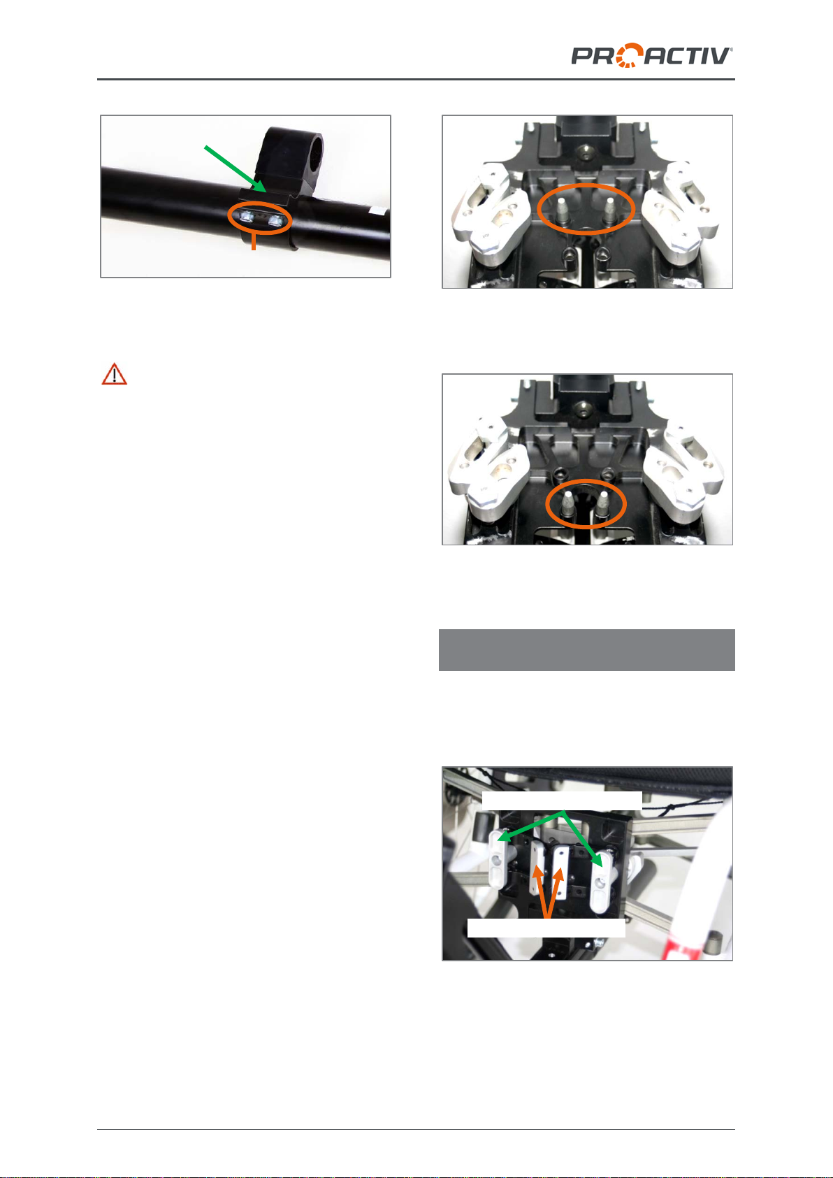
Before you now adapt the adapter to the
wheelchair, check (this is usually pre-installed
by the factory) whether the two centring pins
on the locking plate are mounted correctly for
the size of the central part of the folding
mechanism on the wheelchair (two sizes pos-
sible). To do so, compare the perforation dis-
tance on the folding mechanism with the dis-
tance of the centring pins. If the positioning is
incorrect, you can modify the centring pin posi-
tion by loosening the M5 fixing screws (Metric
size 3 mm). After repositioning the fixing
screws tighten with 4 Nm.
Figure 10: Centring pins assembled for wide centre
part
Figure 11: Centring pins assembled for narrow cen-
tre part
4.3 Adaptation of the adapter on the
wheelchair
Before adapting the wheelchair, the clamp
levers must be released inwards and the lock-
ing heads must be placed in the vertical posi-
tion.
Figure 12: Locking heads in open (vertical) position
and clamp levers released
Locking heads opened
M6 fixing screws
Clamp
Clamp levers released

Usage instructions Adapter & Adaptation
7
Figure 13: Back view of folding mechanism with
open locking sliders
Now the adapters can be attached to the
wheelchair. To do so, slide the adapter from
the front under the folding mechanism and
insert the centring column holder on the cen-
tring column.
Figure 14: Centring column with inserted holder
The centring pins on the locking plate must
reach the drill holes on the front centre piece of
the folding mechanism.
To fix the adapter, the two locking heads on
the locking plate must first be turned by 90° –
lever in horizontal position. Then the two clamp
levers must be firmly tightened externally so
that they generate the necessary force to firmly
adapt the adapter. Only in this position may the
adapter be operated with the adapted product.
Figure 15: Locking heads and clamp levers in
locked position, folding frame adapter assembled
and ready for operation
The tension of the clamp levers in the
new position must always be ensured, i.e.
when the clamp levers are tightened, there
must be no play between the locking sliders
and folding arms and there must always be a
noticeable resistance when tightening the
clamp levers. If necessary, the tension may be
adjusted via the nuts on the locking slider (Met-
ric size 17 mm), after loosening the M5
threaded pins (Metric size 2.5 mm), so that the
tension is the same as it was when new. Even
tension must be ensured on all 4 locking slid-
ers. Once the tension has been set, tighten the
nuts by hand at 20 Nm and the threaded pins
at 4 Nm and secure the threaded pins with
screw locking fluid.
Figure 16: Rear view of folding mechanism with
closed locking sliders, nuts to adjust the tension of
the clamp levers
Locking sliders
Nuts
Clamp levers
tightened
Locking
heads closed
Threaded pins
in the middle
of the nuts

Usage instructions Adapter & Adaptation
8
If the locking heads cannot be turned, this is
usually because the release cord of the folding
mechanism is incorrectly positioned (release
cord in front of the drill holes for the centring
pins) and therefore the locking plate cannot
rest completely on the folding mechanism.
Figure 17: Release cord positioned correctly, drill
holes for centring pins free
Figure 18: Release cord positioned incorrectly, drill
holes for centring pins hidden to the bottom left
If this is not the reason, then the distance of
the locking sliders must be adjusted. To
achieve this the distance measurement via the
nuts on the locking sliders (Metric size 17 mm)
after loosening the M5 threaded pins (Metric
size 2.5 mm) must be adjusted (Fig. 16) so that
the locking heads can be turned and the ten-
sion on the clamp levers is ideal (i.e. when the
clamp levers are tight there can be no play
between the locking sliders and folding arms
and there must always be a noticeable resis-
tance when tightening the clamp levers). Even
tension must be ensured on all 4 locking slid-
ers. Once the distance measurement and ten-
sion has been set, tighten the nuts by hand at
20 Nm and the threaded pins at 4 Nm and
secure the threaded pins with screw locking
fluid.
Note: You can watch a video on attaching the
adapter to the wheelchair on YouTube:
http://www.youtube.com/watch?v=EqY
hslW7HBQ
4.4 Setting options on steering head
The angle-adjustable steering head can influ-
ence various parameters, such as the lifting
distance of the wheelchair steering wheels on
the adapted product, the distance between the
product wheel and wheelchair foot bed, or the
distance of the product's operating elements to
the user's body.
To adjust the angle of the steering head, the
four M6 adjustment screws (Metric size 3 mm)
must first be released on the top and bottom
on the steering head.
Figure 19: M6 adjustment screws at the top of the
steering head connection
After finally loosening the two M6 clamp
screws (Metric size 5 mm), the steering head
can be tilted by 25°. When the right position
has been found, the two clamp screws must be
tightened up again with tightening torque of
7 Nm and secured with screw locking fluid. The
associated nuts (Metric size 17 mm) must be
tightened for this.
M6 adjustment
screws
Steering
head con-
nection

Usage instructions Adapter & Adaptation
9
Figure 20: M6 clamp screws on steering head
Note for NJ1 e-assistant, NJ1 adaptive
bike, SPIKE adaptive bike and Freeway:
When adjusting the angle of the steering head,
you must ensure that the wheel can run freely
(horizontal dimension between the extended
steering axis) between 60 mm and 120 mm.
Figure 21: Free run depending on the angle adjust-
ment of the steering head
When the angle adjustment of the steering
head is completed, the M6 setting screws
(Metric size 3 mm) must be turned again to-
wards the steering head connection so that
they rest on the steering head connection. The
setting screws are used so that the steering
head can no longer turn after the setting has
been made.
Figure 22: M6 setting screws resting on the steering
head connection
5 Central adapter for fixed frame
wheelchairs
The following instructions are intended
for and may only be carried out by a rehabilita-
tion specialist dealer or PRO ACTIV.
The product is coupled using a central adapter
on the wheelchair frame's cross pipes.
Figure 23: Central adapter on the frame cross pipes
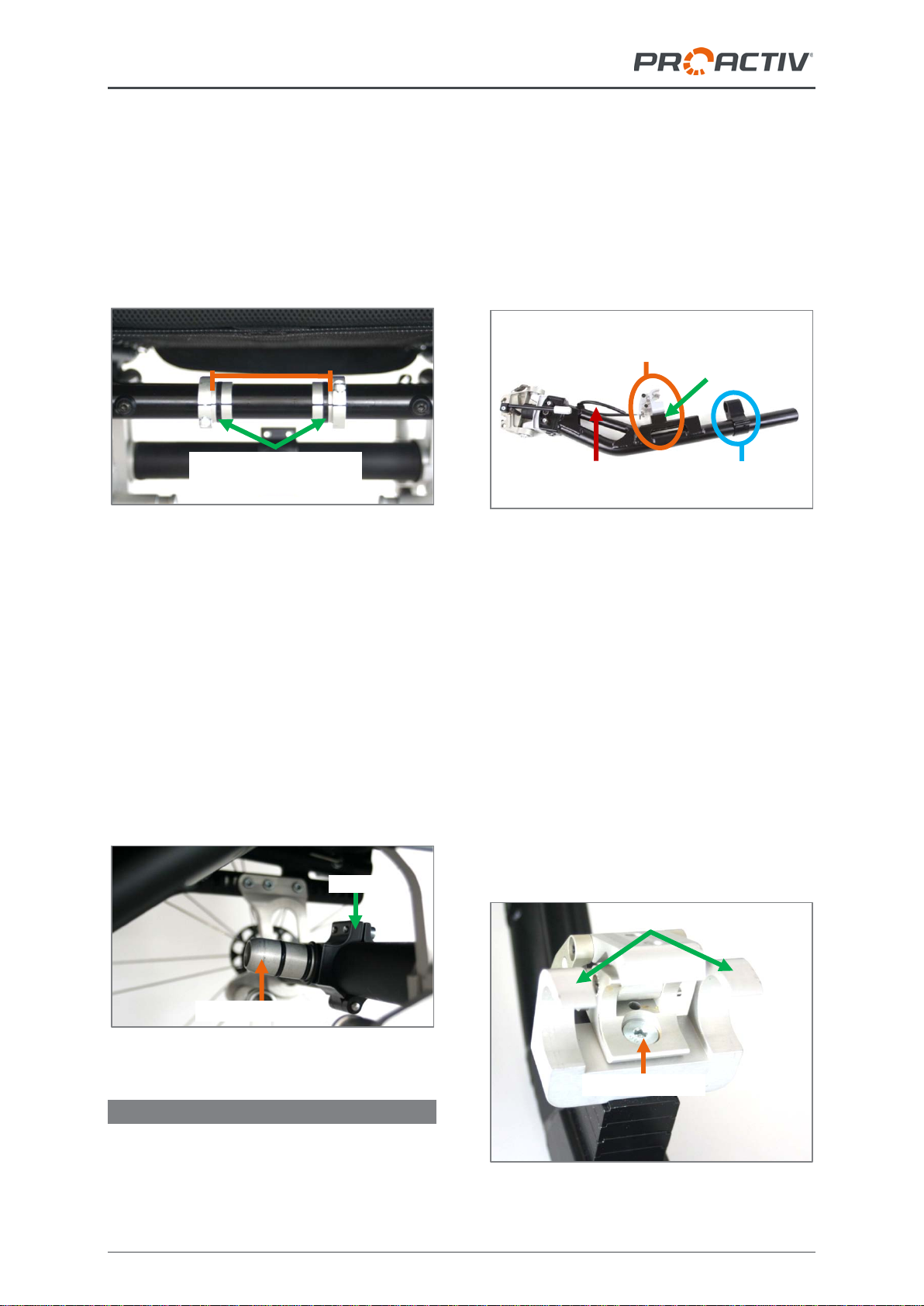
5.1 Assembly work on the wheelchair
In the first step, assemble the two supplied
centring semi-shells (Fig. 24) at a distance of
87 mm (dimension between the two large di-
ameters of the centring semi-shells) at the
centre of the front frame cross tube. This en-
sures the central adaptation of the adapter on
the wheelchair and prevents sideways shifting
during use. The M5 fixing screws (Metric size
4 mm) of the centring semi-shells must be
tightened with a tightening torque of 4 Nm; if
the tightening torque is higher, there is a risk
that the centring semi-shells could break.
M6 clamp screws
60-120 mm
Extended
steering
axis
Wheel con-
tact point
M6 adjustment screws
Usage instructions Adapter & Adaptation
10
Then insert the enclosed cable ties into the
internal grooves on the centring semi-shells
designed for this purpose. When tightening the
cable ties, ensure that their closures are at the
back so that they do not affect the adapter
when it is being adapted. The cable ties ensure
the proper position of the clamping bracket
fixing hooks and thus prevent flapping.
Figure 24: Fully assembled centring semi-shells
Now assemble the centring column with the
terminal clamp on the back frame cross tube.
Before you tighten the M6 fixing screws (Metric
size 5 mm), you must adapt the adapter as
described in Chapter 5.3 and turn the centring
column by twisting the terminal clamp on the
back frame cross tube to the correct angle.
With the adapted adapter, you must then
tighten the fixing screws with a tightening
torque of 7 Nm. Ensure that the centring col-
umn remains located at the centre of the back
frame cross tube.
Figure 25: Centring column with terminal clamp
5.2 Assembly work on adapter
The adapter has adaptation elements that are
pushed onto the fixing elements available or
assembled on the wheelchair and locked in the
adaptation position:
•At the end of the adapter is the centring
column mount; its position is infinitely ad-
justable.
•In the centre of the adapter is the clamping
bracket that can be positioned in a range
of 105 mm in seven 15 mm steps and the
gap between it and the adapter tube can
be adjusted using spacers.
Figure 26: Adaptation elements on the adapter
The adjustment option on the clamping bracket
of 105 mm in seven 15 mm steps as well as
the infinite horizontal adjustment of the cen-
tring column mount enables the horizontal
position of the adapter to be set on the wheel-
chair and adjusts the adapter to the geometry
of the wheelchair. Adapt the adapter to the
wheelchair as described in Chapter 5.3 and
check the necessary adjustment work.
To position the clamping bracket horizon-
tally, the M8 fixing screw (Metric size 5 mm)
must be released and tightened again in the
right thread hole in the fixing rail at 17 Nm and
protected with locking fluid.
Figure 27: M8 fixing screw to horizontally position
the clamping bracket
87 mm
Cable ties on centring
semi-shells
Clamp
Centring column
M8 fixing screw
Fixing hooks
Centring column
mount
Clamping bracket with clamp
levers and fixing hooks
Pull loop on
clamp levers
Spacers

Usage instructions Adapter & Adaptation
11
Figure 28: Positioning the clamping bracket in 15
mm steps
To position the centring column mount
horizontally, loosen the two M6 fixing screws
(Metric size 5 mm). You can now infinitely ad-
just the centring column mount along the
adapter tube. At the desired position, tighten
the fixing screws again with 7 Nm and secure
these with screw locking fluid.
Figure 29: M6 fixing screws to horizontally position
the centring column mount along the adapter tube
When adjusting settings, make sure that the
clamping bracket and centring column mount
are exactly aligned.
When the adapter is attached to the wheel-
chair, the centring column mount should have
around 1 mm play to the terminal clamp on the
centring column (Fig. 30).
Figure 30: Centring column mount on the centring
column
The items delivered include spacers which
can be assembled as required between the
clamping bracket and fixing rail as well as be-
tween the centring column mount and terminal
clamp (fig. 26). The distance that the wheel-
chair steering wheels are lifted off the floor on
the adapted product can be modified by the
assembly / removal of several spacers. When
fitting spacers, it may be necessary to use a
longer M8 fixing screw (Metric size 5 mm).
Make sure that the screw-in depth is at least
12 mm and the fixing screw is not resting on
the adapter tube.
5.3 Adaptation of the adapter on the
wheelchair
Figure 31: Adaptation elements on the adapter and
pull loop on the clamping bracket
First open the adapter's clamp lever by pulling
the pool loops forward in the direction of the
adapter's steering head. Then guide the cen-
tring column mount onto the centring column
on the back cross tube, and then past the fix-
ing hook of the clamping bracket after pushing
Fixing rail with
thread holes
0.5-1 mm play
Centring column terminal clamp
Centring
column
mount
M6 fixing screws
Clamp
Centring column
mount
Clamping bracket with clamp
levers and fixing hooks
Pull loop on
clamp levers
Usage instructions Adapter & Adaptation
12
back the adapter tube (Fig. 27) over the two
centring semi-shells. The fixing hook must sit
with no play on the centring semi-shells (Fig.
32) and may only move sideways by a mini-
mum amount (< 0.5 mm).
Figure 32: Clamp lever with pull loop in the open
position and fixing hook must sit with no play on the
centring semi-shells; for fixed positioning of the
adapter on the wheelchair, the clamp lever must be
pressed until the lock audibly clicks into place
If the distance between the clamping bracket
and centring column mount is set correctly, the
clamping bracket will rest gently on the front
frame cross tube by itself. If this is not the
case, the position must be modified accord-
ingly by sliding the centring column mount
(refer to Chapter 5.2).
Only by pressing the clamping bracket first
from above and then the clamping lever from
the front (Fig. 32) does the knee lever override
and the lock firmly closes on the clamping
bracket. The overriding of the knee lever and
engagement of the lock must be clearly notice-
able and audible. In addition, check the lock to
see if the clamping lever can be opened (do
not pull via the pull loop – this would release
the lock again). If it can't be opened, then at-
tach the pull loop to the front part of the
adapter using a Velcro strap to secure it. This
ensures that the adapter is securely locked
onto the wheelchair and it can be used as in-
tended.
Figure 33: Clamp lever with pull loop in the closed
position, fixed frame adapter mounted and ready for
operation
Figure 34: Centring column mount on the centring
column, fixed frame adapter mounted and ready for
operation
"Lever extension of the quick release
clamp” option: With this option, you do not
have to press the clamp lever under the seat to
close the clamp lever, but you operate the
clamp lever by pressing the lever extension in
front of the wheelchair seat.
Figure 35: "Lever extension of the quick release
clamp” option
Clamp
lever with
pull loop
Closing:
1. Press on the clamping bracket from above
2. Press on the clamp lever from above
Clamp lever with pull loop
0.5-1 mm play
Centring column terminal clamp
Centring
column
mount
Lever extension of the
quick release clamp
The fixing hook
must sit
on the centring
semi-shells
with no play
1.
2.

Usage instructions Adapter & Adaptation
13
Note: You can watch a video on attaching the
adapter to the wheelchair on YouTube:
https://www.youtube.com/watch?v=Z4g
hHsAE4Ok
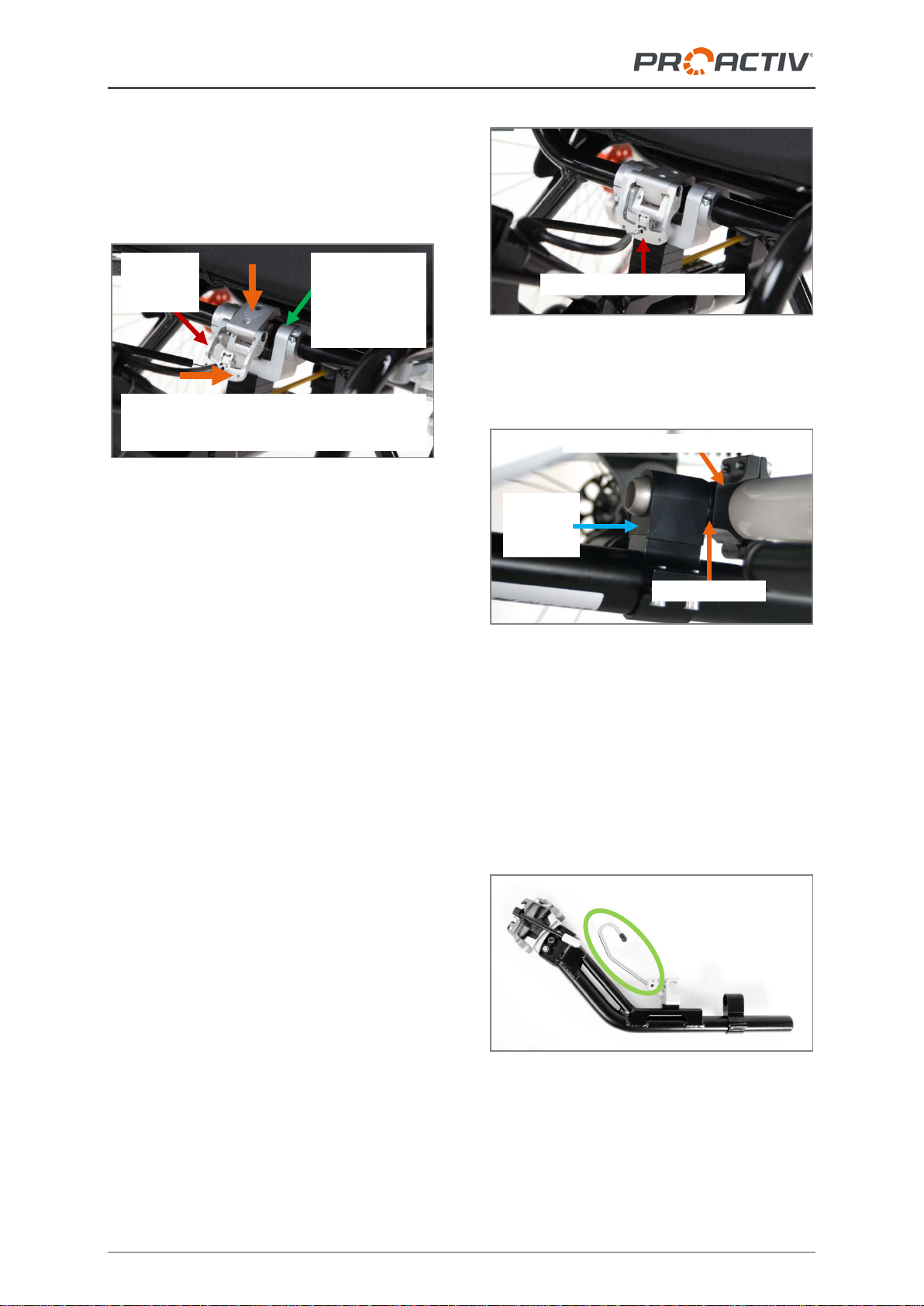
5.4 Setting options for the clamping
bracket
The closing width of the clamping bracket may
need adjusting later if e.g. the clamp lever
cannot be closed or the clamping bracket does
not surround the tube firmly. The width of the
clamping bracket can be adjusted for tube
thicknesses of 24-26 mm.
Figure 36: Clamping bracket closed
Figure 37: Clamping bracket opened
The M5 protection screw (Metric size 2.5 mm)
and the M4 clamp screw (Metric size 2 mm)
must be released for adjustment. This enables
the width of the clamping bracket to be ad-
justed (clockwise for a smaller diameter/anti-
clockwise for a larger diameter) by turning the
eccentric shaft.
Figure 38: M5 securing screw to fix the eccentric
shaft
Figure 39: M4 clamp screw to set the activation
force for opening and closing the clamping bracket
Attention must be paid here to ensure that the
slit on the back of the eccentric shaft points
precisely to one of the marking points attached
to the clamp by turning the eccentric shaft (Fig.
40). This ensures that the securing screw
points precisely to one of the areas attached to
the eccentric shaft for this purpose during
tightening. Only then is independent turning of
the eccentric shaft excluded.
Figure 40: Turning the eccentric shaft along the
marking points (clockwise for smaller Ø, anti-
clockwise for larger Ø)
smaller Ø
M5 securing
screw
M4 clamp
screw
Usage instructions Adapter & Adaptation
14
Figure 41: Eccentric shaft with areas for securing
screw
After completing the width adjustment, first fix
the eccentric shaft again using the M5 securing
screw to 4 Nm and protect with screw locking
fluid. Then adjust the activation force for open-
ing and closing the clamping bracket again
using the M4 clamping screw as per the cus-
tomer's requirements and protected with screw
locking fluid.
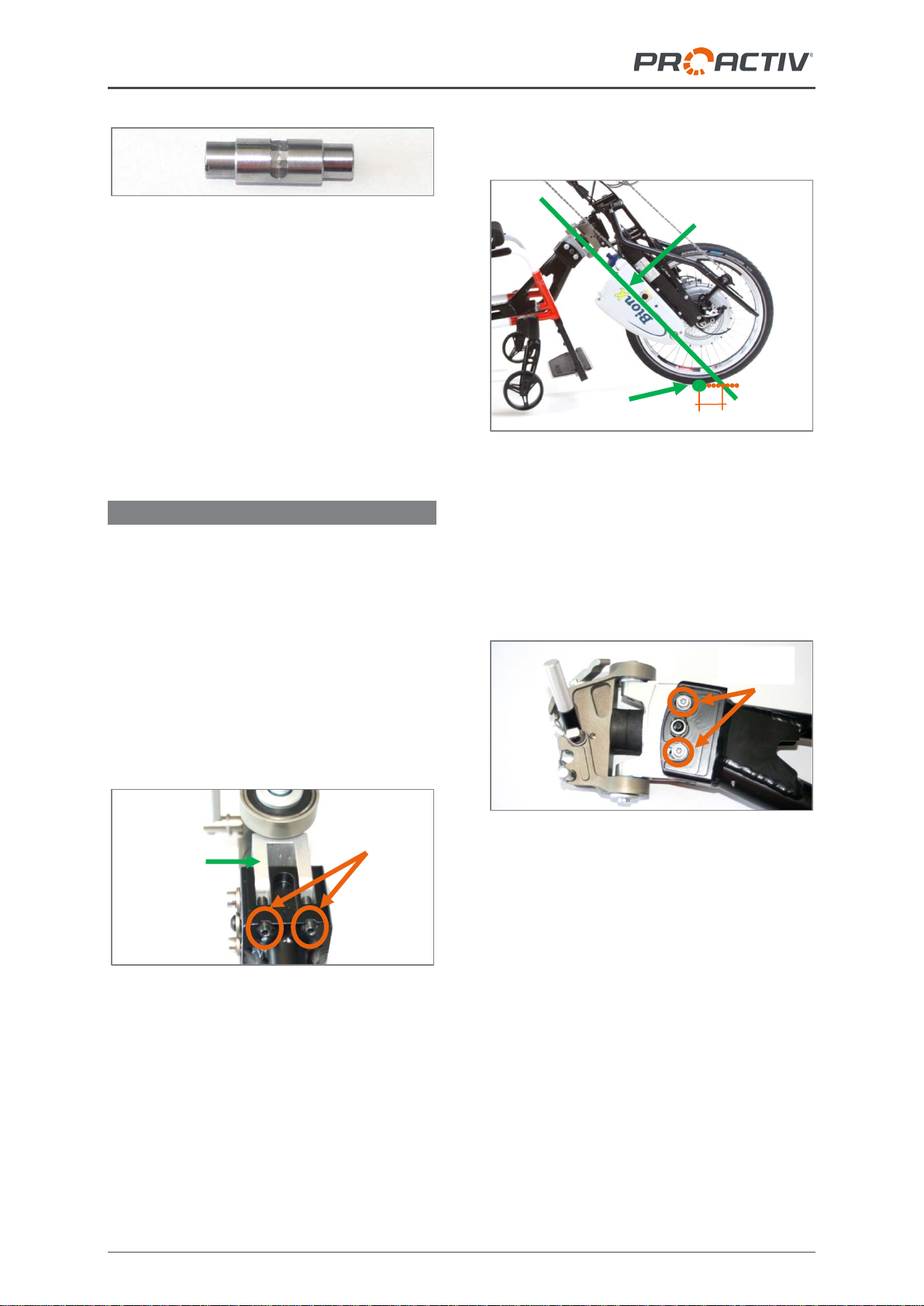
5.5 Setting options on steering head
The angle-adjustable steering head can influ-
ence various parameters, such as the lifting
distance of the wheelchair steering wheels on
the adapted product, the distance between the
product wheel and wheelchair foot bed, or the
distance of the product's operating elements to
the user's body.
To adjust the angle of the steering head, the
four M6 adjustment screws (Metric size 3 mm)
must first be released on the top and bottom
on the steering head.
Figure 42: M6 adjustment screws at the top of the
steering head connection
After then loosening the two M6 clamp screws
(Metric size 5 mm) the steering head can be
tilted by 25° on the side of the steering head
connection. When adjusting the angle of the
steering head, you must ensure that the wheel
can run freely (horizontal dimension between
the extended steering axis) between 60 mm
and 120 mm.
Figure 43: Free run depending on the angle adjust-
ment of the steering head
When the right position has been found, the
two clamp screws must be tightened up again
with a tightening torque of 7 Nm and secured
with screw locking fluid. The associated nuts
(Metric size 17 mm) must be tightened for this.
Figure 44: M6 clamp screws on steering head
Then, the M6 setting screws (Metric size
3 mm) must be turned again towards the steer-
ing head connection so that they rest on the
steering head connection. The M6 setting
screws are used so that the steering head can
no longer turn after the setting has been made.
M6 adjustment
screws
Steering
head
connection
M6 clamp
screws
60-120 mm
Extended
steering axis
Wheel
contact point

Usage instructions Adapter & Adaptation
15
Figure 45: M6 setting screws resting on the steering
head connection
6 Front adapter
The following instructions are intended
for and may only be carried out by a rehabilita-
tion specialist dealer or PRO ACTIV.
The product is attached via one of the adapters
adapted on the wheelchair's front frame tubes.
Figure 46: Front adapter on the front frame tubes
6.1 Assembly work on adapter
The adapter is supplied with standard settings
from the factory depending on the product's
wheel size. The default settings can be viewed
in the table in Chapter 10. If the product is to
be adapted to a third party product or a PRO
ACTIV wheelchair with special dimensions,
changes may still need to be made to the set-
tings. Potential changes stating the dimensions
can also be taken from the table in Chapter 10.
The width of the front adapter must then be
modified to the width of the wheelchair. To
achieve this four M6 tensioning screws on
each side (Metric size 5 mm) must be loos-
ened. By then screwing in all four M4 threaded
screws (Metric size 2 mm), the clamp is
opened and the clamps on the steering head
connection can be moved to the side.
Figure 47: Clamp steering head connection and M6
tensioning screws
Figure 48: M4 threaded pins to open the clamp to
move the clamp steering head connection to the
side
The distance of the two frame clamps must
now be adapted to the distance of the frame
tubes on the wheelchair. The distance of the
frame clamps must be centred so that the
steering head is positioned in the middle.
Clamp steering
head connection
M6 tensioning screws
M4 threaded pins between
the tensioning screws
M6 adjustment screws

Usage instructions Adapter & Adaptation
16
Figure 49: Adaptation elements on the adapter
The M4 threaded pins must then be loosened
again by several turns and the M6 tensioning
screws tightened again with a tightening torque
of 7 Nm and secured with screw locking fluid.
The threaded pins are then screwed in again
gently, making contact with the clamp. The
protruding pieces of tube can be shortened
using a metal saw and the tubes blocked with
the stoppers provided.
Figure 50: Fully assembled adapter with modified
tube lengths and tube end stoppers
6.2 Assembly work on the wheelchair
For adapting to the wheelchair, one of the two
clamp cover stoppers (Fig. 53) supplied must
be mounted on the left as well as the right
frame tube.
In the first step, clamp the front adapter tempo-
rarily on the two frame tubes of the wheelchair.
To achieve this, the frame clamps are first
opened fully (turn clamp lever anti-clockwise).
Then the frame clamps must be attached to
the frame tube. By turning the clamp levers
clockwise, the frame clamps are then fixed
gently to the frame tube.
Now the correct fixing height must be achieved
by moving the adapter on the frame tubes. The
fixing height of the adapter on the wheelchair's
frame tubes is determined by the measure-
ments from the floor to the hook on the inser-
tion shaft on the steering head. This dimension
depends on the wheel size of the product to be
adapted. The guide values are shown below:
20" wheel 490 mm
24" wheel 540 mm
26" wheel 570 mm
Figure 51: Measurement from floor to front of the
insertion shaft
When the adapter sits temporarily in the rele-
vant position on the wheelchair's frame tubes,
the positions of the clamp cover stoppers can
be marked on the back of the wheelchair's
frame tube.
Figure 52: Drawing the position of the clamp frame
stopper on the back of the wheelchair's frame tube
Frame clamps
Steering
head
Clamp lever
Front of
the inser-
tion shaft
Measure-
ment from
floor to
front
Rear wheel-
chair frame
tube
Tube end
stoppers

Usage instructions Adapter & Adaptation
17
The adapter is then removed, the clamp cover
stoppers are inserted on the markings, and the
associated M5 fixing screws (Metric size
4 mm) are tightened with a tightening torque of
4 Nm.
Figure 53: Fully assembled clamp cover stopper
(wheelchair from the side)
6.3 Adaptation of the adapter on the
wheelchair
You now only have to open the frame clamps
fully to adapt the adapter on the wheelchair. To
do so, turn the clamp levers fully anti-
clockwise. Then the frame clamps must be
attached to the frame tube. The height is
shown by the already attached clam cover
stoppers. The frame clamps are then turned by
hand clockwise using the clamp lever.
Figure 54: Fully assembled front adapter
Note on attaching third party products:
PRO ACTIV supports third party attachments
in terms of geometric and functional queries,
but cannot indemnify the person creating the
product/wheelchair combination from the appli-
cable regulations relating to the compulsory
test regulations that always apply to those
creating such aid combinations. PRO ACTIV
does not undertake a compatibility check. All
product tests on the combination must be un-
dertaken by the rehabilitation specialist dealer.
PRO ACTIV is to be indemnified for all defects
or damage on the wheelchair in such a combi-
nation with regard to liability for product defects
or accepting a warranty by the rehabilitation
specialist dealer; this is to be requested from
the relevant wheelchair manufacturer.
6.4 Setting options on steering head
The angle-adjustable steering head can influ-
ence various parameters, such as the lifting
distance of the wheelchair steering wheels on
the adapted product, the distance between the
product wheel and wheelchair foot bed, or the
distance of the product's operating elements to
the user's body.
To adjust the angle of the steering head, the
four M6 adjustment screws (Metric size 3 mm)
must first be released on the top and bottom
on the steering head connection.
Figure 55: M6 adjustment screws at the top of the
steering head connection
After then loosening the two M6 clamp screws
(Metric size 5 mm) the steering head can be
tilted by 25° on the side of the steering head
connection (Fig. 44). When adjusting the angle
of the steering head, you must ensure that the
wheel can run freely (horizontal dimension
between the extended steering axis) between
60 mm and 120 mm.
M6 ad-
justment
screws
Steering
head
connection
M5 fixing screw

Usage instructions Adapter & Adaptation
18
Figure 56: Free run depending on the angle adjust-
ment of the steering head
When the right position has been found, the
two clamp screws must be tightened up again
with a tightening torque of 7 Nm and secured
with screw locking fluid. The associated nuts
(Metric size 17 mm) must be tightened for this.
Figure 57: Nuts for the M6 clamp screws on the
steering head
Then, the M6 setting screws (Metric size
3 mm) must be turned again towards the steer-
ing head connection so that they rest on the
steering head connection. The M6 setting
screws are used so that the steering head can
no longer turn after the setting has been made.
Figure 58: M6 setting screws resting on the steering
head connection
6.5 Changing the distance of the front
adapter to the wheelchair
In order to change the distance of the front
adapter to the wheelchair, the M6 fixing screws
(Metric size 5 mm) that are used to clamp the
clamp covers are loosened and the clamp
covers are pulled out towards the wheelchair
(maximum until the cover is flush with the edge
of the clamp for the steering head connection
on the product side; refer to following image).
The fixing screws are then tightened again at
7 Nm.
Figure 59: Clamp cover fully extended (if possible,
with screw heads also visible)
The clamp covers are also available in various
lengths if the setting range available is not
adequate. Other setting options can be taken
from the table in Chapter 10.
M6 adjust-
ment screws
M6 fixing
screws (back)
Nuts for the
M6 clamp
screws
Clamp cover
60-120 mm
Extended
steering axis
Wheel contact
point

Usage instructions Adapter & Adaptation
19
7 Adaptive bikes NJ1 e-assistant,
NJ1, SPIKE & HUSK-E: Adapta-
tion on the product and detach-
ment from product
The adaptation of the adapter on the product is
shown below using the central adapter and the
NJ1 e-assistant. The approach is also applica-
ble to the front adapter and the NJ1 adaptive
bike, the SPIKE adaptive bike and the HUSK-
E.
With the Adaptive Bike HUSK-E, ensure that
the eccentric clamp lever and the safety bolts
are on the right side. Not on the left side, as is
the case with the other adaptive bikes.
7.1 Terminology
Here you will find an illustration of the terms
used in the following to make it easier for you
understand:
Figure 60: Steering head terms
Figure 61: Docking plate terms
7.2 Adaptation on the product
For the NJ1 e-assistant & HUSK-E:
Please ensure that the drive system is
switched off.
For adaptation, the securing pin on the docking
plate must be pulled out to the outer stop (Fig.
61). On the steering head, the pre-selection
lever lock mechanism must be set to "lock"
(lying flat) and the eccentric clamping lever to
"loose" (Fig. 62).
Figure 62: Adapter settings at the start of adaptation
The product must be fixed with the handbrake
and – if possible – also parked against a wall
(refer to the "Parking brake" chapter in the
product usage instructions). Now move your
wheelchair with the adapted adapter towards
the product until the contact areas on the
adapter and docking plate touch each other.
Figure 63: Moving forward to the product
For adaptation, the insertion bolt of the docking
plate must be inserted into the insertion shaft
on the steering head.
Pre-selection lever
grid mechanism
Eccentric clamp
lever
Mount for
safety bolts
Insertion shaft
Eccentric clamp lever to "loose"
Pre-selection grid mechanism to "lock"
Direction
of travel
Insertion bolt
Securing bolt
Other manuals for NJ1 e-assistant
1
This manual suits for next models
2
Table of contents
Other Proactive Wheelchair manuals


