Antar AT52320 User manual

AT52320, AT52321
WÓZEK INWALIDZKI ELEKTRYZCNY INSTRUKCJA OBSŁUGI
ELECTRIC WHEELCHAIR USER MANUAL
GEBRAUCHSANWEISUNG FÜR ELEKTROROLLSTUHL

PL
WSTĘP
Przed pierwszą próbą obsługi wózka inwalidzkiego z napędem elektrycznym należy przeczytać i przestrzegać wszystkich zaleceń, ostrzeżeń i uwag zawartych w
niniejszej instrukcji. Jeżeli jakiekolwiek informacje zawarte w niniejszej instrukcji nie są zrozumiałe lub jeżeli potrzebna jest dodatkowa pomoc przy montażu lub
obsłudze, prosimy o kontakt ze sprzedawcą. Bezpieczne użytkowanie produktu jest uzależnione od przestrzegania zaleceń, przestróg i ostrzeżeń zawartych w
niniejszej instrukcji. Nie ponosimy odpowiedzialności za jakiekolwiek szkody i/lub obrażenia powstałe w wyniku indywidualnego, niebezpiecznego działania lub
nieprzestrzegania zaleceń, przestróg i ostrzeżeń zawartych w niniejszej instrukcji. Niniejsze instrukcje mają na celu zapewnienie maksymalnego bezpieczeństwa.
Zrozumienie instrukcji jest podstawowym warunkiem bezpiecznej obsługi wózka inwalidzkiego.
SPECYFIKACJA
Rozmiar całkowity(dł.*szer.*wys.): 1125*630*1305 mm
Wysokość siedziska: 515 mm
Szerokość siedziska: 440 mm
Głębokość siedziska: 450 mm
Wysokość podłokietników: 200 mm
Wysokość oparcia: 800 mm
Waga akumulatora: 4,2 kg
Waga wózka inwalidzkiego wraz z akumulatorem: 40,1 kg
Prędkość maksymalna: 6km/h
Droga hamowania przy prędkości 6km/h: ≤ 1500 mm
Maks. promień skrętu: ≤ 1200 mm
Obciążenie użytkowe: 120 kg
Teoretyczny zasięg na jednym ładowaniu: 28 km
Stabilność statyczna: ≥ 9°
Stabilność dynamiczna: ≥ 6°
Zdolność pokonywania wzniesień: 6°
Specyfikacja silnika: 24V/250W*2
Specyfikacja akumulatora: 24V/20Ah*l
Maksymalny prąd wyjściowy urządzenia sterującego: 2A
Prąd wyjściowy akumulatora: 30A
Lane koła przednie: średnica zewnętrzna 190 mm
Pneumatyczne koła tylne: średnica zewnętrzna 405 mm
OPIS
Wózek inwalidzki z napędem składa się głównie z kilku części:
Rama fotela: składa się ze składanego elementu, który można złożyć od środka podstawy fotela w celu wygodnego przechowywania lub transportu.
System działania: składa się z urządzenia sterującego, komory akumulatora, dwóch silników, zestawu mechanizmów napędowych i kół napędowych.
Komora akumulatora znajduje się pod siedzeniem, mieści się w niej akumulator o napięciu 24 V i pojemności 20 AH oraz jego zabezpieczenia
przeciążeniowe. Gniazdo ładowarki akumulatora znajduje się z tyłu urządzenia sterującego.
Niniejszy wózek inwalidzki z napędem jest wyposażony w dwie ręczne dźwignie wolnego biegu umieszczone na mechanizmie napędowym.
Regulowanie dźwigni może zatrzymać wózek inwalidzki.
1. Rączka dla opiekuna
2. poduszka oparcia
3. Hamulec ręczny
4. Pneumatyczne koło tylne
5. Lane koła przednie
6. Podłokietnik antypoślizgowy
7. Odłączany podnóżek
8. Oparcie na łydki
9. Płyta podnóżka
10. Zdejmowany zagłówek
11. Tylne, dodatkowe urządzenie sterujące (model AT52320)
12. Zdalne, dodatkowe urządzenie sterujące (model AT52321)
1
2
3
4
5
6
7
8
9
10
11
12

MONTAŻ
1. Wyjąć wózek z opakowania i położyć go na ziemi. Rozsunąć ramę wózka z lewej i prawej strony i wcisnąć dwie rurki po obu stronach podstawy
siedziska w rowki po obu stronach ramy wózka. (patrz rys. 2)
1.
Podnieść do góry rączki i zablokować urządzenie składające.(patrz rys. 3)
2.
Podłączyć wtyczkę wiązki przewodów akumulatora do gniazda wiązki przewodów znajdującego się na ramie.
3.
Odkręcić śruby i uszczelki od trzpienia urządzenia sterującego, następnie założyć urządzenie sterujące i dopasować do plastikowych uszczelek,
założyć śrubę i dokręcić śrubokrętem (patrz rys. 5), następnie przymocować wiązkę przewodów do ramy za pomocą plastikowych opasek
kablowych (patrz rys. 6).
rys.2 rys.3
5.
Podłączyć wtyczkę wiązki przewodów urządzenia sterującego z gniazdem wiązki przewodów akumulatora (patrz rys. 7).
6.
Zamontować element mocujący podnóżka na górnej rurze lewej lub prawej ramy (patrz rys. 8). A następnie obrócić podnóżki do przodu, aby zostały
automatycznie zablokowane, po czym rozłożyć je. (patrz rys. 9)
7.
Założyć pasek podtrzymujący nogi na prawej i lewej górnej rurce, a następnie skorzystać z taśmy nylonowej.
8.
Wyregulować wysokość podnóżka, odkręcić nakrętkę zabezpieczającą po obu stronach podnóżka, wyciągnąć śruby, (patrz rys.
11
), przesunąć w
górę i w dół rurę teleskopową, ustawić dogodną wysokość, następnie włożyć śruby i dokręcić nakrętkę.
rys. 10
rys. 8
rys. 6
rys. 7
rys. 9
rys. 11
rys. 5
rys. 4

UŻYTKOWANIE
Urządzenie sterujące
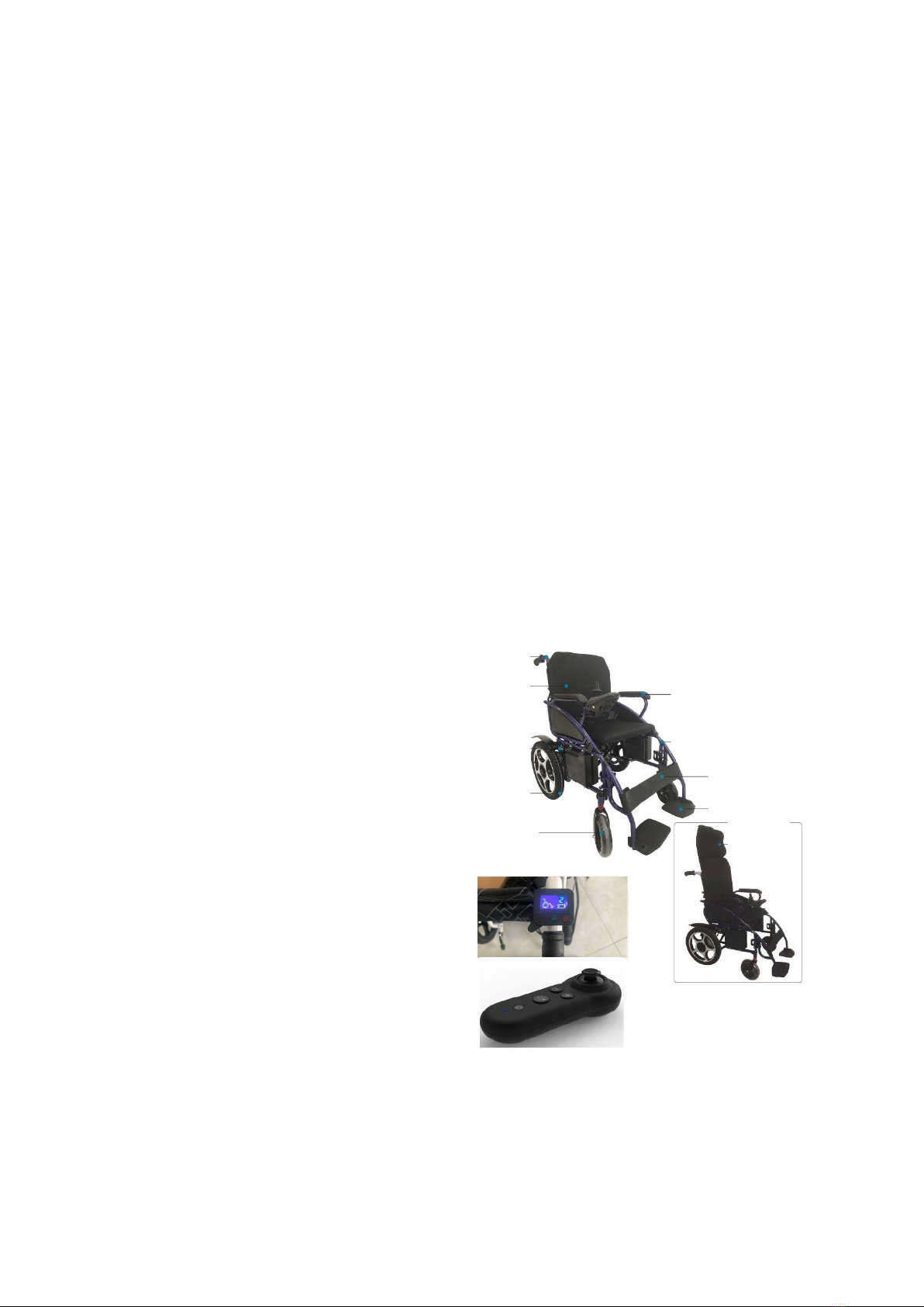
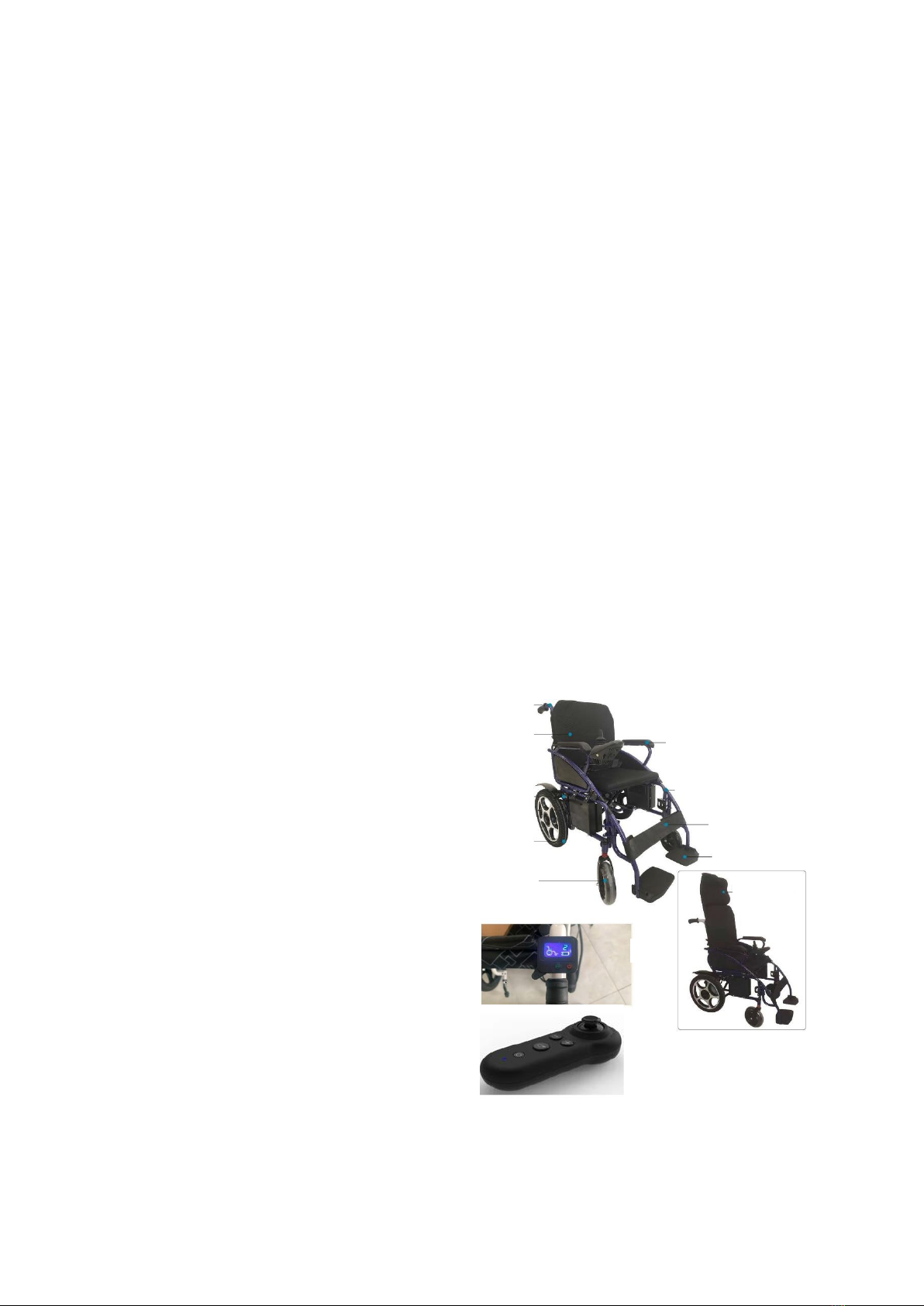
Urządzenie sterujące jest kluczowym elementem wyposażenia wózka inwalidzkiego.
Wszystkie elementy elektryczne do obsługi wózka inwalidzkiego znajdują się w urządzeniu sterującym
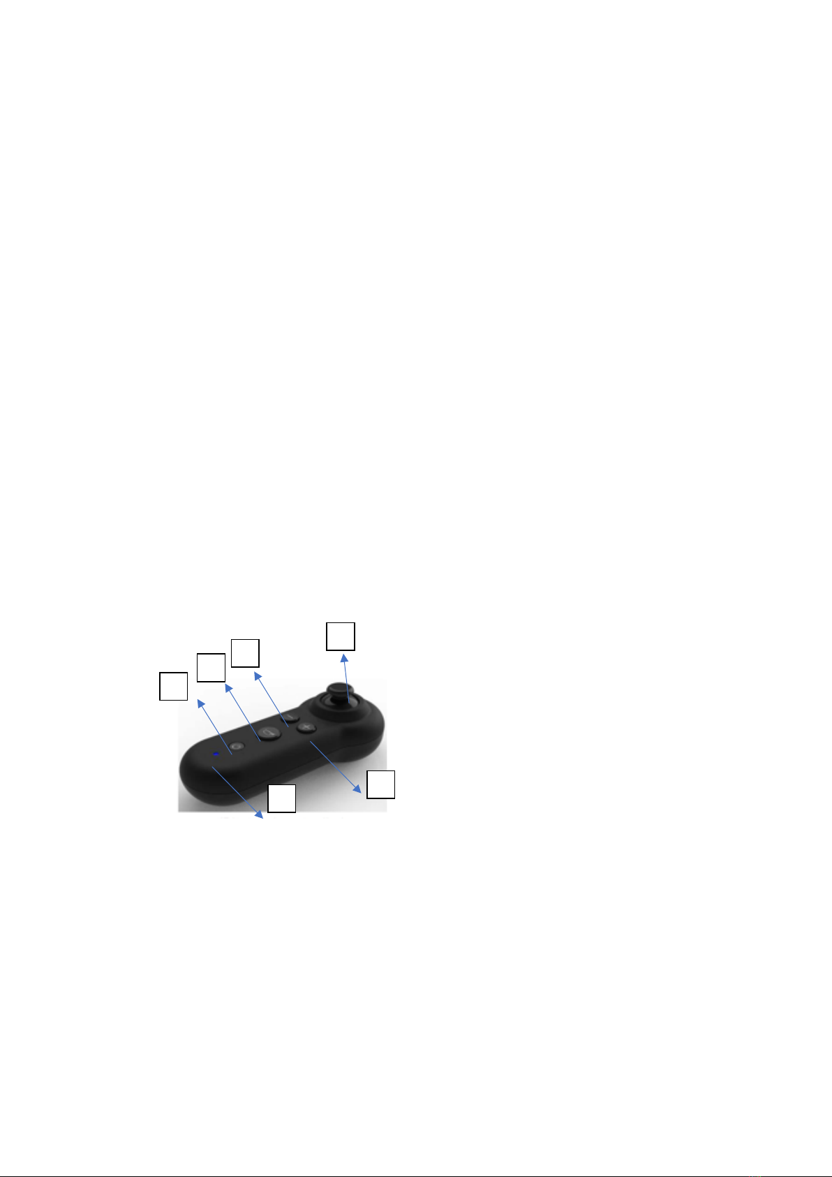
Urządzenie sterujące składa się z następujących części:
1. Joystick
2.Wskaźnik poziomu naładowania akumulatora
3.Przycisk On/Off
4.Kontrolka prędkości
5.Przycisk zwiększania prędkości
6.Przycisk zmniejszania prędkości
Jeżeli wózek inwalidzki porusza się w nieoczekiwanym kierunku, należy natychmiast zwolnić joystick, co spowoduje zatrzymanie wózka.
7. Przycisk klaksonu
8. Gniazdo ładowarki
Urządzenie sterujące znajduje się zazwyczaj na jednym z podłokietników i jest podłączone do akumulatora wraz z silnikami.
Przycisk włączania/wyłączania
Steruje zasilaniem elektroniki urządzenia sterującego, które następnie napędza silniki, nie należy używać przycisku włączania/wyłączania do
zatrzymywania wózka inwalidzkiego, o ile nie wystąpi sytuacja awaryjna, w przeciwnym razie może dojść do skrócenia żywotności elementów napędu.
Joystick
Joystick służy głównie do sterowania prędkością i kierunkiem jazdy wózka. Im dalej przesunie się joystick od pozycji centralnej, tym szybciej porusza się
wózek. Po zwolnieniu joysticka, wraca on automatycznie do pozycji centralnej i następuje automatyczne hamowanie.
OSTRZEŻENIE!
Jeżeli wózek inwalidzki przypadkowo się poruszy, proszę natychmiast zwolnić joystick, aby wózek przestał się poruszać automatycznie,
chyba że joystick jest niesprawny.
Przycisk klaksonu
Po naciśnięciu tego przycisku włączy się klakson.
Przyciski zwiększania/ zmniejszania prędkości
Po włączeniu zasilania, kontrolka prędkości wskaże maksymalną prędkość, z jaką porusza się obecnie wózek inwalidzki. Zakres maksymalnej prędkości
wskazywanej przez liczbę kontrolkę prędkości może być regulowany przez użytkowników. Każde naciśnięcie przycisku zwiększania prędkości (lub
zmniejszania prędkości) powoduje zwiększenie lub zmniejszenie prędkości o jedną jednostkę.
Dźwignia hamulca
Jeśli nie korzystamy z wózka inwalidzkiego, należy pociągnąć dźwignię hamulca do tyłu, aby docisnęła koła, co spowoduje unieruchomienie wózka.
Jeśli korzystamy z wózka inwalidzkiego (czy to w sposób automatyczny, czy ręczny), należy popchnąć do przodu dźwignię hamulca, aby upewnić się, że dźwignia
nie dociska kół. Patrz rys. 12
rys. 12
UWAGA: Kiedy nie ma potrzeby jazdy po pochyłościach, dźwignia hamulca musi być przesunięta do przodu, w przeciwnym razie wózek inwalidzki straci
sterowność i może doprowadzić do urazów ciała.
Pas bezpieczeństwa
Dla własnego bezpieczeństwa należy zawsze zapinać pas bezpieczeństwa. Zatrzasnąć klamrę pasa tak, aby usłyszeć kliknięcie .
Ładowanie akumulatora
Oddzielna ładowarka akumulatora jest główną częścią wózka inwalidzkiego. Dzięki niej można naładować wózek w szybki i prosty sposób.
OSTRZEŻENIE! Akumulator wózka należy ładować za pomocą dostarczonej ładowarki. Nie korzystać z ładowarek przeznaczonych do samochodów.
Naładować akumulator przy użyciu oddzielnej ładowarki dostarczonej wraz z wózkiem:
•Upewnić się, że urządzenie sterujące jest wyłączone, a wózek nie znajduje się w trybie wolnego biegu.
•Podłączyć 3-biegunową metalową wtyczkę ładowarki do 3-biegunowego gniazda ładowarki na urządzeniu sterującym (patrz rys. 13).
•Włożyć wtyczkę wejściową ładowarki do ściennego gniazdka elektrycznego.
•Zapalenie się czerwonej diody LED na ładowarce oznacza, że ładowanie jest w toku. Zapalenie się zielonej diody LED na ładowarce oznacza, że akumulator
jest w pełni naładowany.
•Czas pracy wynosi około 8-12 po jednym ładowaniu.
•Po zakończeniu ładowania należy najpierw wyjąć wtyczkę wejściową ładowarki z gniazda ściennego, a następnie wtyczkę wyjściową z gniazda w urządzeniu
sterującym. Włożyć ładowarkę z kablami i wtyczkami razem do torby z tyłu oparcia fotela.
rys.13 rys. 14
Zabezpieczenie przeciążeniowe
W przypadku przeciążenia silników, zabezpieczenie przeciążeniowe odłączy zasilanie, aby chronić silniki i ich elementy elektryczne. W celu przywrócenia funkcji
ochronnej należy skorzystać z pomocy fachowców, która polega na odkręceniu śruby w skrzynce akumulatora, wymianie bezpiecznika, ponownym przykryciu
pokrywy akumulatora, a następnie przykręceniu śruby.
Środki ostrożności
Upewnić się, że urządzenie sterujące zostało solidnie zamontowane, a joystick w pozycji centralnej jest ustawiony pionowo do góry.

Należy siedzieć pewnie, zapiąć pas bezpieczeństwa, oprzeć się o oparcie i podnieść głowę, aby uniknąć urazów w czasie jazdy.
Po włączeniu zasilania należy najpierw sprawdzić, czy maksymalna prędkość wskazywana przez kontrolkę prędkości na urządzeniu sterującym odpowiada
użytkownikowi. Jeżeli nie, należy ją wyregulować za pomocą przycisku zwiększania lub zmniejszania prędkości na urządzeniu sterującym. Ze względów
bezpieczeństwa sugerujemy rozpoczęcie jazdy od mniejszej prędkości, a następnie stopniowe zwiększanie prędkości.
Jeżeli wózek inwalidzki porusza się w nieoczekiwanym kierunku, należy natychmiast zwolnić joystick, co spowoduje zatrzymanie wózka.
Uwaga:
Stopy należy trzymać w obrębie podnóżków, nie należy ich z nich wysuwać.
Uwaga
: Podczas jazdy nie należy wyciągać rąk z podłokietników.
Uwaga
: Przed rozpoczęciem użytkowania lub pozostawieniem wózka należy upewnić się, że nie znajduje się on w trybie wolnego biegu.
Zagrożenia
Nie wolno używać wózka w następujących przypadkach:
1. Przypadki zabronione w niniejszej instrukcji obsługi, takie jak przekroczenie maksymalnego nachylenia, zbyt wysokie przeszkody, autostrady, pasy
jazdy dla pojazdów silnikowych
2. W niektórych miejscach lub na powierzchniach, takich jak mokre trawiaste zbocze, gdzie wózek może wpaść w poślizg.
3. W przypadku konieczności naprawy systemu sterowania lub innych ważnych elementów.
Zakłócenia elektromagnetyczne
Wózek może poruszać się w obszarach dotkniętych zakłóceniami elektromagnetycznymi pochodzącymi od niektórych nadajników radiowych, takich jak
radio, interkom bezprzewodowy, telefony komórkowe, radary itp. W tych przypadkach mogą one wpływać na prowadzenie wózka.
OSTRZEŻENIE!
Urządzenia elektroniczne mogą być narażone na działanie zakłóceń elektromagnetycznych (EMI). Takie zakłócenia mogą pochodzić od
stacji radiowych, telewizyjnych, telefonów komórkowych i innych nadajników radiowych. Jeżeli wózek inwalidzki wykazuje nietypowe działanie
spowodowane zakłóceniami elektromagnetycznymi, należy wyłączyć zasilanie i skonsultować się z pracownikiem serwisu. Firma nie ponosi żadnej
odpowiedzialności prawnej za straty spowodowane nieprzestrzeganiem tego warunku.
WSKAZANIA
Produkt jest przeznaczony do wygodnego transportu osób o ograniczonej zdolności lub braku zdolności chodzenia. Wózek jest zaprojektowany do transportu
jednej osoby.
PRZECIWWSKAZANIA
ograniczenia fizyczne lub umysłowe (np. upośledzenie wzroku), które uniemożliwiają bezpieczne obchodzenie się z produktem.
SKŁADANIE I PRZECHOWYWANIE WÓZKA INWALIDZKIEGO
W celu transportu i przechowywania wózka inwalidzkiego należy go złożyć w następujący sposób.
1. Postawić wózek inwalidzki na ziemi. Odłączyć zasilanie.
2. Obrócić podnóżki do góry i obrócić na zewnątrz o 90° (patrz rys. 15).
3. Odchylić dźwignię podnóżka na zewnątrz, obrócić o 90°, a następnie wyciągnąć ją (patrz rys. 16).
4. Zacisnąć obie dźwigienki umożliwiające składanie po obu stronach rączki i opuścić rączkę w dół (patrz rys. 17).
5. Pociągnąć podstawę siedzenia do góry za jej środek, a następnie złożyć wózek inwalidzki (patrz rys. 18)
rys. 15 rys. 16
rys. 17 rys. 18
DODATKOWE KONTROLERY
AT52320
1. Przewód połączeniowy
2. Wyświetlacz LCD
3. Włączenie/wyłączenie zasilania
4. Tryby pracy
5. Dźwignia wychylna umożliwiająca jazdę do przodu i tyłu
6. Oznaczenie wózka inwalidzkiego (podświetlone w stanie roboczym)
7. Wskaźnik biegu
8. Wskaźnik naładowania baterii
9. Otwory montażowe w pionie, M4.0
10. Otwory montażowe w poziomie, m4.0
11,12. Otwory na śruby
INSTRUKCJA OBSŁUGI TYLNEGO URZĄDZENIA STERUJĄCEGO,
WSKAZÓWKI MONTAŻOWE

1. Najpierw należy zamontować element mocujący, a następnie tylne
urządzenie sterujące na prawej rączce wózka inwalidzkiego, używając
do tego klucza imbusowego.
2. Włożyć końcówkę XLR/USB przewodu łączącego tylne urządzenie s
terujące do portu ładowania (XLR lub USB) głównego urządzenia sterującego
wózka inwalidzkiego i przymocować przewód opaską.
2. WŁĄCZANIE/WYŁĄCZANIE TYLNEGO URZĄDZENIA STERUJĄCEGO
1. Przytrzymać przycisk "Zasilanie" przez 2s, aż tylne urządzenie sterujące
zostanie włączone.
2. Nacisnąć przycisk "TRYB", aby wybrać odpowiedni bieg w zależności
od potrzeb (zakres biegów: 1-5).
3. UŻYTKOWANIE
Po wykonaniu kroków 1 i 2 operator tylnego urządzenia sterującego
powinien trzymać obiema rękami uchwyty wózka inwalidzkiego, a prawym
kciukiem sterować dźwignią wychylną. Podczas popychania dźwigni do
przodu, wózek inwalidzki porusza się do przodu i odwrotnie; gdy dźwignia
wraca do pozycji centralnej w sposób naturalny,
elektryczny wózek inwalidzki nie porusza się.
4. ALARM SYGNALIZUJĄCY USTERKĘ I ŚRODKI ZARADCZE
Najczęściej występujące problemy:
a) Wózek inwalidzki pozostaje nieruchomy niezależnie od tego, czy dźwignia jest przesuwana do przodu czy do tyłu;
b) Wózek inwalidzki wciąż się porusza, nawet gdy dźwignia powróci do pozycji centralnej;
W przypadku wystąpienia tych zjawisk należy sprawdzić parametry dźwigni wychylnej:
1. Odłączyć przewód łączący od głównego urządzenia sterującego;
2. Przytrzymać przycisk "Tryb", w międzyczasie połączyć tylne urządzenie sterujące z głównym urządzeniem sterującym; gdy tylne urządzenie sterujące wejdzie
w tryb weryfikacji, zwolnić przycisk "Tryb" i popchnąć dźwignię do przodu i do tyłu co najmniej dwa razy (Uwaga: dźwignię należy popchnąć najdalej jak to
możliwe). Po powrocie dźwigni do pozycji centralnej należy ponownie nacisnąć przycisk "Tryb", aby zapisać zweryfikowane dane i zakończyć proces.
AT52321
1. Włączanie/wyłączanie
2. Klakson
3. Przycisk zwalniania
4. Przycisk sterujący
5. Przycisk przyspieszania
6. Status RGP
PAROWANIE KONTROLERA
Umieść dwie bateria AAA w kontrolerze, następnie naciśnij przycisk włączania na głównym
sterowniku wózka a dopiero później na dodatkowym.
Gdy status RGP wskazuje niebieskie światło, które miga co 2s, naciśnij przycisk klaksonu i spowolnienia
Dopóki niebieskie światło nie zacznie świecić się stale. Parowanie zostało poprawnie zakończone.
1
2
3
4
5
6

CZYSZCZENIE I KONSERWACJA
1. Pielęgnacja i konserwacja po użyciu
Wyłączyć zasilanie (najlepiej odłączyć wszystkie połączenia kablowe).Nie dopuścić, aby dzieci i osoby nieświadome dotykały wózka. Wózek inwalidzki powinien
być przechowywany w chłodnym i suchym miejscu, aby zapobiec jego reformacji i zachować jego właściwości na dłużej. Użyć czystej i miękkiej szmatki do
czyszczenia ramy, a następnie pozostawić do wyschnięcia.
2. Rutynowe kontrole
Przed każdą jazdą należy przeprowadzić kontrolę swojego wózka, aby utrzymać go zawsze w jak najlepszym stanie. Ponadto należy przeprowadzać
kontrolę wózka raz na tydzień, raz na miesiąc i raz na pół roku zgodnie z pozycjami w tabeli 2.
3. Rozwiązywanie problemów
Wózek ten jest wyposażony w funkcję automatycznego alarmu, który informuje o jego nieprawidłowym działaniu. Jeśli wózek nie jest w pełni sprawny,
na urządzeniu sterującym zapalą się diody
LED
i rozlegnie się brzęczyk, co umożliwi wykrycie usterki zgodnie z pozycjami w tabeli 3.
Jeżeli po usunięciu usterek wciąż występują problemy, należy skontaktować się z autoryzowanym serwisem.
Tabela 2 Podstawowe sposoby rozwiązywania problemów
Numer alarmu
Wyświetlacz LED
Objaśnienie
1
1 mignięcie diody LED
Niska pojemność akumulatora
2
2 mignięcia diody LED
Awaria lewego silnika
3
3 mignięcia diody LED
Awaria lewego hamulca
4
4 mignięcia diody LED
Awaria prawego silnika
5
5 mignięć diody LED
Awaria prawego hamulca
6
6 mignięć diody LED
Przeciążenie urządzenia sterującego
7
7 mignięć diody LED
Awaria joysticka
8
8 mignięć diody LED
Awaria samego urządzenia sterującego
9
9 mignięć diody LED
Awaria urządzenia sterującego
Tabela 3 Rutynowe kontrole
Pozycja
Zawsze
Raz w
tygodniu
Raz w miesiącu
Raz na pół roku
Każda z części
Obracanie, jazda, ustawianie i demontaż
i tak dalej
Hamulce
Wiązki przewodów i kable
Naładowanie akumulatora
Mobilność kół przednich
Skrzynka sterowania pneumatycznego
tylnych kół
Zużycie opon
Uszkodzenie kół
Zużycie uchwytu, oparcia i podstawy
fotela
Silniki
Urządzenie sterujące
Czystość

ŻYWOTNOŚĆ
Okres użytkowania wózka inwalidzkiego w warunkach klinicznych zależy nie tylko od wytrzymałości konstrukcyjnej samego produktu,
ale także od środowiska i przyzwyczajeń użytkowników produktu, od tego, czy przeprowadzane są okresowe przeglądy, konserwacja itp. Dlatego
kluczem do zagwarantowania jak najdłuższej żywotności jest ścisłe przestrzeganie przez użytkownika niniejszej instrukcji.
Uwaga!
W ramach pielęgnacji i konserwacji, w przypadku konieczności wymiany akumulatora, joysticka, silnika/napędu, ładowarki i innych części
serwisowych, prosimy o bezpośredni kontakt z naszą firmą w celu wymiany części na nowe, oryginalne.
UWAGA:
W przypadku wystąpienia związanego w wyrobem „poważnego incydentu”, który bezpośrednio lub pośrednio doprowadził, mógł doprowadzić lub może
doprowadzić do któregokolwiek z niżej wymienionych zdarzeń:
a) zgonu pacjenta, użytkownika lub innej osoby lub
b) czasowego lub trwałego pogorszenia stanu zdrowia pacjenta, użytkownika lub innej osoby lub
c) poważnego zagrożenia zdrowia publicznego
należy powyższy „poważny incydent” zgłosić producentowi oraz właściwemu organowi państwa członkowskiego, w którym użytkownik lub pacjent mają miejsce
zamieszkania. W przypadku Polski właściwym organem jest Urząd Rejestracji Produktów Leczniczych, Wyrobów Medycznych i Produktów Biobójczych.
UWAGA:
W przypadku wystąpienia bólu, reakcji alergicznych lub innych niepokojących, niejasnych dla użytkownika objawów związanych z użytkowaniem wyrobu
medycznego należy skonsultować się z pracownikiem służby zdrowia.
UWAGA: zabronione jest użytkowanie produktu w sposób inny niż zgodnie z jego przeznaczeniem
UWAGA: Przed użytkowaniem należy sprawdzić czy wszystkie elementy zostały zmontowane poprawnie.
UWAGA: Producent nie ponosi odpowiedzialności za uszkodzenia spowodowane zaniedbaniem konserwacji, nieodpowiednim serwisowaniem bądź będące
skutkiem nieprzestrzegania zaleceń zawartych w niniejszej instrukcji obsługi
UWAGA: W przypadku nieprawidłowego korzystania z wyrobu może zaistnieć ryzyko wywrócenia się. Prosimy o przestrzeganie zaleceń dotyczących
wsiadania/zsiadania/poruszania się.
UWAGA: Podczas użytkowania i obsługi wyrobu oraz podczas jego składania i regulowania mechanizmów może zaistnieć niebezpieczeństwo uwięźnięcia i/lub
ściśnięcia części ciała użytkownika/osoby towarzyszącej w otworach/szczelinach pomiędzy elementami. Należy wykonywać te czynności szczególnie ostrożnie.
Po zakończeniu regulacji ustabilizować pozycję poprzez dokładne dokręcenie nakrętek/śrub
Niniejszy symbol oznacza maksymalną wagę użytkownika!
SPOSÓB UTYLIZACJI WYROBU PO WYCOFANIU Z EKSPLOATACJI
Po wycofaniu wyrobu z eksploatacji wyrób medyczny można zutylizować jak zwykły odpad komunalny z wyjątkiem wyrobów elektrycznych – należy postępować
w sposób właściwy dla utylizacji sprzętu elektrycznego i elektronicznego.

ENG
INTRODUCTION
Before attempting to operate your power wheelchair for the first time, please read and observe all recommendations, warnings, and cautions in this manual. If any of
the information in this manual is not understood, or if additional assistance is required for assembly or operation, please contact your dealer. The safe use of the
product depends on compliance with the recommendations, cautions and warnings contained in this manual. We shall not be liable for any damage and/or injury
resulting from individual unsafe operation or failure to observe the recommendations, cautions and warnings contained in this manual. These instructions are intended
to ensure maximum safety. Understanding the instructions is an essential requirement for the safe operation of the wheelchair.
SPECIFICATIONS
Overall size(L*W*H): 1125*630*1305 mm
Seat height: 515 mm
Seat width: 440 mm
Seat depth: 450 mm
Height of armrests: 200 mm
Backrest height: 800 mm
Battery weight: 4.2 kg
Weight of wheelchair including battery: 40.1 kg
Maximum speed: 6km/h
Stopping distance at 6km/h: ≤ 1500 mm
Max. turning radius: ≤ 1200 mm
Payload: 120 kg
Theoretical range on a single charge: 28 km
Static stability: ≥ 9°
Dynamic stability: ≥ 6°
Climbing capacity: 6°
Motor specification: 24V/250W*2
Battery specification: 24V/20Ah*l
Maximum output current of the control unit: 2A
Battery output current: 30A
Front wheels: outer diameter 190 mm
Inflatable rear wheels: outer diameter 405 mm
DESCRIPTION
The powered wheelchair consists mainly of several parts:
Seat frame: consists of a folding component that can be folded from the centre of the seat base for convenient storage or transport. Operating system: consists of a
control unit, a battery compartment, two motors, a set of drive mechanisms and drive wheels.
The battery compartment is located under the seat, housing a 24 V, 20 AH battery and its overload protection. The battery charger socket is located at the rear of the
control unit. This power wheelchair is equipped with two manual slow-speed levers located on the drive mechanism. Adjusting the levers can stop the wheelchair.
DESCRIPTION
1. handle for the carer
2. backrest cushion
3. hand brake
4. pneumatic rear wheel
5. lane front wheels
6. anti-slip armrest
7. detachable footrest
8. calf rest
9. footrest plate
10. removable headrest
11. Rear additional control device (model AT52320)
12. remote additional control (model AT52321)
1
2
3
4
5
6
7
8
9
10
11
12

ASSEMBLY
1. Remove the trolley from the packaging and lay it on the ground. Unfold the frame of the pushchair on the left and right sides and push the two tubes on
either side of the seat base into the grooves on either side of the frame of the pushchair (see fig. 2).
2. Lift up the handles and lock the folding device (see fig. 3).
3. Remove the screws and gaskets from the stem of the control unit, then insert the control unit and fit into the plastic gaskets, insert the screw and tighten
with a screwdriver (see fig.5)
4. Then fix the wire harness to the frame with plastic cable ties (see fig.6).
Fig. 2 Fig. 3
5. Connect the control unit wiring harness plug to the battery wiring harness socket (see fig. 7).
6. Fit the footrest attachment to the top tube of the left or right frame (see fig. 8). And then rotate the footrests forward so that they are automatically
locked, then unfold them (see fig. 9).
7. Attach the leg support strap to the right and left upper tube, then use the nylon strap.
8. Adjust the height of the footrest, unscrew the lock nut on either side of the footrest, remove the bolts, (see fig. 11), move up and down the telescopic
tube, adjust to a convenient height, then insert the bolts and tighten the nut.
Fig. 10
Fig. 8
Fig. 6
Fig. 7
Fig. 9
Fig. 11
Fig. 5
Fig. 4

USE
Control device
The control device is a key piece of wheelchair equipment.
All electrical components for operating the wheelchair are contained in the control device.
The control device consists of the following parts:
1. Joystick
2. Battery level indicator
3. On/Off button
4. Speed indicator
5. Increase speed button
6. Button for decreasing speed
If the wheelchair moves in an unexpected direction, release the joystick immediately, which will bring the wheelchair to a stop.
7. Horn button
8. Charger socket
The control unit is usually located on one of the armrests and is connected to the battery along with the motors.
On/Off button
Controls the power supply to the electronics of the control unit, which then drives the motors, do not use the on/off button to stop the wheelchair
unless there is an emergency, otherwise the life of the drive components may be reduced.
Joystick
The joystick is mainly used to control the speed and direction of the wheelchair. The further you move the joystick from the central position, the faster the
trolley moves. When the joystick is released, it automatically returns to the central position and automatic braking takes place.
WARNING
If the wheelchair accidentally moves, please release the joystick immediately so that the wheelchair stops moving automatically, unless the joystick is
faulty.
Horn button
When this button is pressed, the horn will be activated.
Speed increase/decrease buttons
When the power is switched on, the speed light will indicate the maximum speed at which the wheelchair is currently moving. The range of maximum
speed indicated by the speed light number can be adjusted by users. Each time the speed up (or speed down) button is pressed, the speed is increased
or decreased by one unit.
Brake lever
If not using a wheelchair, pull the brake lever backwards to apply pressure to the wheels, which will immobilise the wheelchair.
If using a wheelchair (whether automatic or manual), push the brake lever forward to ensure that the lever does not press on the wheels (see fig. 12).
rys. 12
NOTE
When there is no need to drive on an incline, the brake lever must be moved forward, otherwise the wheelchair will lose steering and could lead to personal
injury.
Seat belt
For your own safety, always fasten the seat belt. Engage the belt buckle so that you hear a click.
Charging the battery
The separate battery charger is the main part of the wheelchair. With it you can charge the wheelchair quickly and easily.
WARNING
The wheelchair battery must be charged using the charger provided. Do not use chargers designed for cars.
Charge the battery using the separate charger supplied with the wheelchair:
- Ensure that the control unit is switched off and the wheelchair is not in slow mode.
- Plug the 3-pin metal charger plug into the 3-pin charger socket on the control unit (see fig. 13).
- Insert the input plug of the charger into a wall socket.
- The lighting of the red LED on the charger indicates that charging is in progress. When the green LED on the charger lights up, it means that the battery is fully
charged.
- The operating time is approximately 8-12 after one charge.
- When charging is complete, first remove the charger input plug from the wall socket and then the output plug from the socket on the control unit. Place the
charger with cables and plugs together in the bag on the back of the seat back.
Fig.13

Overload protection
If the motors are overloaded, the overload protection will disconnect the power supply to protect the motors and their electrical components. Expert
assistance is required to restore the protective function, which involves unscrewing the screw in the battery box, replacing the fuse, re-covering the battery
cover, and then tightening the screw.
Precautions
Ensure that the control unit is securely mounted and that the joystick in the central position is upright.
Sit securely, fasten your seat belt, lean against the backrest, and raise your head to avoid injury while driving.
When the power is switched on, first check that the maximum speed indicated by the speed indicator light on the control unit corresponds to the user.
If it does not, adjust it using the up or down speed button on the control unit. For safety reasons, we suggest starting at a lower speed and then gradually
increasing the speed.
If the wheelchair moves in an unexpected direction, release the joystick immediately, which will bring the wheelchair to a stop.
Note
Keep your feet within the footrests, do not extend them out of the footrests
.
Do not extend your hands from the armrests while driving
.
Make sure the wheelchair is not in slow motion mode before operating or leaving the wheelchair.
Hazards
Do not use the wheelchair in the following cases:
1. cases prohibited in this manual, such as exceeding the maximum gradient, obstacles that are too high, motorways, motor vehicle lanes
2. in certain locations or on surfaces, such as wet grassy slopes, where the wheelchair may slip.
3. when the control system or other important components need to be repaired.
Electromagnetic interference
The wheelchair may run in areas affected by electromagnetic interference from certain radio transmitters such as radios, wireless intercoms, mobile
phones, radar, etc. In these cases, the handling of the trolley may be affected.
WARNING! Electronic equipment can be exposed to electromagnetic interference (EMI). Such interference can come from radio stations, television
stations, mobile phones, and other radio transmitters. If the wheelchair exhibits abnormal operation due to electromagnetic interference, switch off the
power supply and consult a service technician. The company accepts no legal liability for losses caused by non-compliance with this condition.
INDICATIONS
The product is designed to comfortably transport people with limited or no walking ability. The wheelchair is designed to transport one person.
CONTRAINDICATIONS
Physical or mental limitations (e.g., visual impairment) that prevent safe handling of the product.
FOLDING AND STORING THE WHEELCHAIR
To transport and store the wheelchair, fold it as follows.
1. place the wheelchair on the ground. Disconnect the power supply.
2. turn the footrests upwards and rotate outwards by 90° (see fig. 15).
3. pivot the footrest lever outwards, rotate it 90° and then pull it out (see fig. 16).
4. clamp the two folding levers on either side of the handle and lower the handle down (see fig. 17).
5. pull the seat base upwards by its centre and then fold the wheelchair (see fig. 18).
fig. 15 fig. 16
fig. 17 fig. 18
ADDITIONAL CONTROLLERS
AT52320
1. Connection cable
2. LCD display
3. Power on/off
4. Operating modes
5. Pivoting lever for forward and reverse travel
6. Wheelchair sign (illuminated in working condition)
7. Gear indicator
8. Battery charge indicator
9. Vertical mounting holes, M4.0 10.
10. horizontal mounting holes, m4.0
11., 12. Bolt holes

REAR CONTROL UNIT OPERATING INSTRUCTIONS
1. First install the attachment piece and then the rear control unit on the right-hand handle of the wheelchair, using the allen key to do so.
2. Plug the XLR/USB end of the rear device connection cable into the charging port (XLR or USB) on the wheelchair's main control unit and secure the cable with
a cable tie.
SWITCHING THE REAR CONTROL UNIT ON/OFF
1. Hold down the "Power" button for 2s until the rear control device is switched on.
2. Press the "MODE" button to select the appropriate gear as required (gear range: 1-5).
USE
After steps 1 and 2, the operator of the rear control unit should hold the wheelchair handles with both hands and use his right thumb to control the pivoting
lever. While pushing the lever forward, the wheelchair moves forward and vice versa; when the lever returns to the central position naturally, the electric
wheelchair does not move.
FAULT INDICATION ALARM AND REMEDIES
Most common problems:
(a) The wheelchair remains stationary regardless of whether the lever is moved forwards or backwards.
(b) The wheelchair continues to move even when the lever is returned to the central position.
If these phenomena occur, check the parameters of the pivoting lever:
1. Disconnect the connecting cable from the main control unit.
2. Hold down the "Mode" button, meanwhile connect the rear control unit to the main control unit; when the rear control unit enters the verification mode,
release the "Mode" button, and push the lever forward and backward at least twice (Note: push the lever as far as possible). Once the lever has returned to the
central position, press the "Mode" button again to save the verified data and complete the process.
AT52321
1. Switch on/off
2. Horn
3. Release button
4. Control button
5. Acceleration button
6. RGP status
PAIRING THE CONTROLLER
Place two AAA batteries in the controller, then press the power button on the main.
When the RGP status indicates a blue light that flashes every 2s, press the horn and deceleration button.
Until the blue light is on continuously. The pairing has been correctly completed.
1
2
3
4
5
6

CLEANING AND MAINTENANCE
Care and maintenance after use
Switch off the power supply (preferably disconnect all cable connections).Do not allow children or unsuspecting persons to touch the wheelchair. Store the
wheelchair in a cool and dry place to prevent it from reforming and to preserve its properties for longer. Use a clean and soft cloth to clean the frame and then
allow to dry.
Routine checks
Before every ride, you should carry out an inspection of your trolley to keep it always in the best possible condition. In addition, inspect your trolley weekly,
monthly and every six months according to the items in Table 2.
Troubleshooting
This trolley is equipped with an automatic alarm function that alerts you to malfunctions. If the trolley is not fully operational, the LEDs on the control unit will
light up and a buzzer will sound to detect the fault according to the items in Table 3.
If problems persist after troubleshooting, contact an authorised service centre.
Table 2 Basic troubleshooting
Number alert
LED display
Explanation
1
1 LED flashing
Low battery capacity
2
2 LED flashes
Left motor fault
3
3 LED flashes
Left brake fault
4
4 LED flashes
Failure of right motor
5
5 LED flashes
Failure of right hand brake
6
6 LED flashes
Control unit overload
7
7 LED flashes
Failure of the joystick
8
8 LED flashes
Failure of the control unit itself
9
9 LED flashes
Control unit failure
Table 3 Routine checks
Frequency
Always
Weekly
Monthly
Every 6 months
All parts
X
Turning, driving, adjusting, and
dismantling, etc.
X
Brake
X
Wiring harnesses and cables
X
Battery
X
Agility of the front wheels
X
Pneumatic control box for the rear
wheel
X
Tire wear
X
Wheel damage
X
Handle, backrest, foot
X
Engines
X
Control panel
X
Cleanliness
X

LIFETIME
We carried out a fatigue test covering the control unit, battery, motors, drive and frame of our trolley. The lifespan of the control device, drive and frame is on
average 10 years, while the motor and battery are spare parts and therefore have a lifespan of up to 7 years.
The lifetime of a wheelchair in a clinical setting depends not only on the structural strength of the product itself, but also on the environment and the habits
of the users of the product, whether periodic inspections, maintenance etc. are carried out. Therefore, the key to guaranteeing the longest possible service
life is strict adherence by the user to this manual.
WARRANTY
Five year guarantee on the frame of the trolley.
Within one year from the date of purchase, for the following parts, we provide a free maintenance and replacement service to the original customer after the
dealer has checked and found defects in materials and workmanship.
- Electric or lever control system
- Motor/drive system
- Shaft bearing and bushing
Six month battery warranty.
Please note that the warranty service is carried out by the dealer in conjunction with our after-sales department.
Outside warranty
- ABS plastic cover and rubber washer
- Tyres
- Decorative parts
- Damage due to abuse, mishandling, accidents and negligence
- Business use or other abnormal use
Please note that as part of care and maintenance, if you need to replace the battery, joystick, motor/drive, charger, and other service parts, please contact our
company directly to replace the parts with new, original parts.
NOTICE
In the event of a device-related "serious incident" that has directly or indirectly led to, could have led to or may lead to any of the following:
(a) death of a patient, user, or other person, or
(b) temporary or permanent deterioration of the health of a patient, user, or other person, or
(c) a serious risk to public health
the above 'serious incident' must be notified to the manufacturer and to the competent authority of the Member State in which the user or patient is resident.
In the case of Poland, the competent authority is the Office for Registration of Medicinal Products, Medical Devices and Biocidal Products.
In case of pain, allergic reactions or other disturbing symptoms unclear to the user related to the use of the medical device, consult a healthcare professional.
It is forbidden to use the product other than for its intended purpose.
Before use, check that all components have been assembled correctly.
The manufacturer will not be held responsible for damage caused by negligent maintenance, inadequate servicing or as a result of not following the instructions
in this manual.
There may be a risk of tipping over if the product is used incorrectly. Please observe the instructions for getting on/off/rolling.
During use and handling of the product and when folding and adjusting the mechanisms, there may be a danger that parts of the user's/companion's body
become trapped and/or pinched in the openings/gaps between components. Perform these operations with particular care. After adjustment, stabilise the
position by tightening the nuts/bolts firmly.
This symbol indicates the maximum weight of the user!
HOW TO DISPOSE OF THE PRODUCT AT END-OF-LIFE
After the device has been taken out of service, the medical device can be disposed of as normal household waste with the exception of electrical products -
follow the procedures for the disposal of electrical and electronic equipment.

DE
EINFÜHRUNG
Bevor Sie Ihren Elektrorollstuhlzum ersten Mal in Betrieb nehmen, lesen und beachten Sie bitte alle Empfehlungen,Warnhinweise und Vorsichtsmaßnahmen in dieser
Anleitung. Wenn Sie eine der Informationen in dieser Anleitung nicht verstehen oder wenn Sie zusätzliche Hilfe bei der Montage oder Bedienung benötigen, wenden
Sie sich bitte an Ihren Händler. Die sichere Verwendung des Produkts hängt von der Einhaltung der in diesem Handbuch enthaltenen Empfehlungen,
Vorsichtsmaßnahmen und Warnhinweise ab. Wir haften nicht für Schäden und/oder Verletzungen, die durch unsicheren Betrieb oder Nichtbeachtung der in diesem
Handbuch enthaltenen Empfehlungen, Vorsichtsmaßnahmen und Warnungen entstehen. Diese Anweisungen sollen ein Höchstmaß an Sicherheit gewährleisten. Das
Verständnis der Anleitung ist eine wesentliche Voraussetzung für den sicheren Betrieb des Rollstuhls.
SPEZIFIKATIONEN
Gesamtgröße (L*B*H): 1125*630*1305 mm
Sitzhöhe: 515 mm
Sitzbreite: 440 mm
Sitztiefe: 450 mm
Höhe der Armlehnen: 200 mm
Höhe der Rückenlehne: 800 mm
Gewicht der Batterie: 4,2 kg
Gewicht des Rollstuhls einschließlich Batterie: 40,1 kg
Höchstgeschwindigkeit: 6km/h
Anhalteweg bei 6km/h: ≤ 1500 mm
Max. Wenderadius: ≤ 1200 mm
Nutzlast: 120 kg
Theoretische Reichweite mit einer einzigen Ladung: 28 km
Statische Stabilität: ≥ 9°
Dynamische Stabilität: ≥ 6°
Steigfähigkeit: 6°
Spezifikation des Motors: 24V/250W*2
Spezifikation der Batterie: 24V/20Ah*l
Maximaler Ausgangsstrom des Steuergeräts: 2A
Ausgangsstrom der Batterie: 30A
Vorderräder: Außendurchmesser 190 mm
Aufblasbare Hinterräder: Außendurchmesser 405 mm
BESCHREIBUNG
Der Elektrorollstuhl besteht hauptsächlich aus den folgenden Komponenten:
Sitzrahmen: besteht auseinem klappbaren Teil, das von der Mitte der Sitzfläche aus zusammengeklapptwerden kann, um den Rollstuhl bequem zu verstauen oderzu
transportieren.
Betriebssystem: besteht aus einer Steuereinheit, einem Batteriefach, zwei Motoren, einer Reihe von Antriebsmechanismen und Antriebsrädern.
Das Batteriefach befindet sich unter dem Sitz und beherbergt eine 24-V-Batterie mit 20 AH und einen Überlastungsschutz. Der Anschluss für das Batterieladegerät
befindet sich auf der Rückseite des Steuergeräts.
Dieser Elektrorollstuhl ist mit zwei manuellen Langsamfahrhebeln ausgestattet, die sich am Antriebsmechanismus befinden. Durch Verstellen der Hebel kann der
Rollstuhl angehalten werden.
1. Pflegergriff
2. Rückenlehnenpolster
3. Handbremse
4. luftbereiftes Hinterrad
5. Fahrspur Vorderräder
6. Anti-Rutsch-Armlehne
7. abnehmbare Fußstütze
8. Wadenlehne
9. Fußrastenplatte
10. abnehmbare Kopfstütze
11. Hinteres zusätzliches Steuergerät (Modell AT52320)
12. zusätzliche Fernsteuerung (Modell AT52321)
2
6
7
8
9
10
11
12
1
3
4
5

MONTAGE
1. Nehmen Sie den Rollstuhl aus der Verpackung und legen Sie ihn auf den Boden. Klappen Sie den Rahmen des Rollstuhls von der linken und rechten Seite
auf und schieben Sie die beiden Rohre auf beiden Seiten der Sitzfläche in die Nuten (siehe Abb. 2).
2. Heben Sie die Griffe an und verriegeln Sie die Faltvorrichtung (siehe Abb. 3).
3. Entfernen Sie die Schrauben und Dichtungen vom Schaft des Steuergeräts, setzen Sie das Steuergerät ein und setzen Sie es in die Kunststoffdichtungen
ein. Setzen Sie anschließend die Schraube ein und ziehen Sie sie mit einem Schraubenzieher fest (siehe Abb. 5).
4. Danach befestigen Sie den Kabelbaum mit Kunststoffkabelbindern am Rahmen (siehe Abb. 6).
Abb.2 Abb.3
5. Verbinden Sie den Kabelbaumstecker der Steuereinheit mit der Buchse des Batteriekabelbaums (siehe Abb. 7).
6. Installieren Sie die Fußrastenbefestigung am oberen Rohr des linken oder rechten Rahmens (siehe Abb. 8). Drehen Sie dann die Fußstützen nach
vorne, sodass sie automatisch einrasten, und klappen Sie sie dann aus. (siehe Abb. 9)
7. Bringen Sie den Beinstützengurt am rechten und linken oberen Rohr an und verwenden Sie dann den Nylongurt.
8. Stellen Sie die Höhe der Fußstütze ein, lösen Sie die Sicherungsmutter auf beiden Seiten der Fußstütze, entfernen Sie die Schrauben (siehe Abb. 11),
bewegen Sie das Teleskoprohr auf und ab, stellen Sie eine angenehme Höhe ein, setzen Sie die Schrauben ein und ziehen Sie sie fest.
Abb.10
Abb.8
Abb.6
Abb.7
Abb.9
Abb.11
Abb.5
Abb.4

VERWENDEN
Kontrollgerät
Das Steuergerät ist ein zentrales Element der Rollstuhlausstattung.
Alle elektrischen Komponenten zum Betrieb des Rollstuhls befinden sich im Steuergerät.
Das Steuergerät besteht aus folgenden Teilen:
1. Joystick
2. Batteriestandsanzeige
3. Ein/Aus-Taste
4. Geschwindigkeitsanzeige
5. Geschwindigkeitserhöhungstaste
6. Taste zur Geschwindigkeitsreduzierung
Wenn sich der Rollstuhl in eine unerwartete Richtung bewegt, lassen Sie den Joystick sofort los und der Rollstuhl stoppt.
7. Hupenknopf
8. Ladebuchse
Das Steuergerät befindet sich meist an einer der Armlehnen und ist zusammen mit den Motoren mit der Batterie verbunden.
An / aus Schalter
Es steuert die Stromversorgung der Elektronik der Steuereinheit, die dann die Motoren antreibt. Verwenden Sie den Ein-/Ausschalter nicht, um den Rollstuhl
anzuhalten, es sei denn, es handelt sich um einen Notfall, da sonst die Lebensdauer der Antriebskomponenten verkürzt werden kann.
Joystick
Der Joystick wird hauptsächlich verwendet, um die Geschwindigkeit und Richtung des Staplers zu steuern. Je weiter Sie den Joystick von der Mittelposition
entfernen, desto schneller bewegt sich der Rollstuhl. Beim Loslassen des Joysticks kehrt dieser automatisch in die Mittelstellung zurück und es erfolgt eine
automatische Bremsung.
ACHTUNG
Wenn sich der Rollstuhl versehentlich bewegt, lassen Sie den Joystick bitte sofort los! Dann sollte der Rollstuhl automatisch stoppen. Ist dies nicht der Fall,
hat der Joystick eine Fehlfunktion.
An / aus Schalter
Es steuert die Stromversorgung der Elektronik der Steuereinheit, die die Motoren antreibt. Verwenden Sie den Ein-/Ausschalter nicht, um den Rollstuhl
anzuhalten, es sei denn, es handelt sich um einen Notfall, da sonst die Lebensdauer der Antriebskomponenten verkürzt werden kann.
Hupenknopf
Die Hupe ertönt, wenn diese Taste gedrückt wird.
Beschleunigungs-/Abschalttasten
Beim Einschalten zeigt die Geschwindigkeitsanzeige die Höchstgeschwindigkeit an, mit der der Rollstuhl derzeit fährt. Der maximale
Geschwindigkeitsbereich, der durch die Anzahl der Geschwindigkeitsanzeigeleuchten angezeigt wird, kann vom Benutzer angepasst werden. Mit jedem
Drücken der Speed Up oder Speed Down Taste wird die Geschwindigkeit um eine Stufe erhöht oder verringert.
Bremshebel
Wenn der Rollstuhl nicht benutzt wird, ziehen Sie den Bremshebel zurück, sodass er gegen die Räder drückt, wodurch der Rollstuhl blockiert wird.
Wenn Sie einen Rollstuhl verwenden (ob automatisch oder manuell), drücken Sie den Bremshebel nach vorne, um sicherzustellen, dass der Hebel nicht auf die
Räder drückt (siehe Abb. 12).
Abb. 12
ACHTUNG
Der Bremshebel muss nach vorne bewegt werden, wenn Steigungen nicht befahren werden müssen, da der Rollstuhl sonst die Kontrolle verliert und zu
Verletzungen führen kann.
Sicherheitsgurt
Legen Sie zu Ihrer eigenen Sicherheit immer einen Sicherheitsgurt an. Schließen Sie die Gürtelschnalle, bis Sie ein Klicken hören.
Aufladen des Akkus
Das separate Batterieladegerät ist der Hauptteil des Rollstuhls. Dank ihm können Sie den Rollstuhl schnell und einfach aufladen.
ACHTUNG
Der Rollstuhlakku muss mit dem mitgelieferten Ladegerät aufgeladen werden. Verwenden Sie keine Autoladegeräte.
Laden Sie den Akku mit dem separaten im Lieferumfang enthaltenen Ladegerät auf:
• Stellen Sie sicher, dass das Steuergerät ausgeschaltet ist und sich der Rollstuhl nicht im Freilaufmodus befindet.
• Verbinden Sie den 3-poligen Ladestecker aus Metall mit der 3-poligen Ladebuchse am Steuergerät (siehe Abb. 13).
• Stecken Sie den Eingangsstecker des Ladegeräts in eine Wandsteckdose.
• Wenn die rote LED am Ladegerät aufleuchtet, wird geladen. Wenn die grüne LED am Ladegerät aufleuchtet, ist der Akku vollständig geladen.
• Die Laufzeit beträgt ca. 8-12 Stunden mit einer einzigen Ladung.
• Ziehen Sie nach Abschluss des Ladevorgangs zuerst den Eingangsstecker des Ladegeräts aus der Steckdose und dann den Ausgangsstecker aus der Buchse
am Steuergerät. Legen Sie das Ladegerät mit Kabeln und Steckern zusammen in die Tasche auf der Rückseite der Sitzlehne.
Abb.13

Überladeschutz
Wenn die Motoren überlastet sind, trennt der Überladeschutz die Stromversorgung, um die Motoren und ihre elektrischen Komponenten zu schützen. Für
die Wiederherstellung der Schutzfunktion ist fachkundige Hilfe erforderlich, bei der die Schraube im Batteriekasten abgeschraubt, die Sicherung ausgetauscht,
die Batterieabdeckung wieder abgedeckt und anschließend die Schraube angezogen wird.
Vorsichtsmaßnahmen / Inbetriebnahme
Vergewissern Sie sich, dass das Steuergerät fest montiert ist und der Joystick in der mittleren Position aufrecht steht.
Setzen Sie in den Rollstuhl, schnallen Sie sich an, lehnen Sie sich gegen die Rückenlehne und heben Sie den Kopf, um Verletzungen während der Fahrt zu
vermeiden.
Überprüfen Sie nach dem Einschalten des Geräts zunächst, ob die von der Geschwindigkeitsanzeige auf dem Steuergerät angezeigte Höchstgeschwindigkeit mit
der gewünschten des Benutzers übereinstimmt. Wenn dies nicht der Fall ist, stellen Sie die Geschwindigkeit mit der Auf- oder Abwärtstaste auf dem Steuergerät
ein. Aus Sicherheitsgründen empfehlen wir, mit einer niedrigeren Geschwindigkeit zu beginnen und die Geschwindigkeit dann allmählich zu erhöhen.
Wenn sich der Rollstuhl in eine unerwartete Richtung bewegt, lassen Sie den Joystick sofort los, wodurch der Rollstuhl zum Stillstand kommt.
Hinweise
Halten Sie Ihre Füße innerhalb der Fußstützen, strecken Sie sie nicht aus den Fußstützen heraus.
Strecken Sie Ihre Hände während der Fahrt nicht aus den Armlehnen.
Vergewissern Sie sich, dass der Rollstuhl fest steht, bevor Sie den Rollstuhl bedienen oder verlassen.
Gefahren
Benutzen Sie den Rollstuhl nicht in den folgenden Fällen:
1. Fälle, die in diesem Handbuch verboten sind, wie Überschreitung der maximalen Steigung, zu hohe Hindernisse, Autobahnen, Kraftfahrzeugspuren
2. an bestimmten Orten oder auf Oberflächen, wie z. B. nassen Grasböschungen, auf denen der Rollstuhl rutschen kann.
3. wenn das Steuerungssystem oder andere wichtige Komponenten defekt sind und/oder repariert werden müssen.
Elektromagnetische Störungen
Der Rollstuhl kann in Gebieten mit elektromagnetischen Störungen durch bestimmte Funksender wie Radios, drahtlose Gegensprechanlagen, Mobiltelefone,
Radar usw. betrieben werden. In diesen Fällen kann die Handhabung des Rollstuhl beeinträchtigt werden.
WARNUNG! Elektronische Geräte können elektromagnetischen Störungen (EMI) ausgesetzt sein. Solche Störungen können von Radiosendern, Fernsehsendern,
Mobiltelefonen und anderen Funksendern ausgehen. Wenn der Rollstuhl aufgrund von elektromagnetischen Störungen nicht ordnungsgemäß funktioniert,
schalten Sie die Stromversorgung aus und wenden Sie sich an einen Servicetechniker. Das Unternehmen übernimmt keine Haftung für Schäden, die durch die
Nichteinhaltung dieser Bedingung entstehen.
INDIKATIONEN
Das Produkt ist für den bequemen Transport von Menschen mit eingeschränkter oder fehlender Gehfähigkeit konzipiert. Der Rollstuhl ist für den Transport einer
Person ausgelegt.
KONTRAINDIKATIONEN
Körperliche oder geistige Einschränkungen (z. B. Sehschwäche), die einen sicheren Umgang mit dem Produkt verhindern.
FALTUNG UND LAGERUNG DES ROLLSTUHLS
Um den Rollstuhl zu transportieren und zu lagern, falten Sie ihn wie folgt.
1. Stellen Sie den Rollstuhl auf den Boden. Trennen Sie die Stromzufuhr.
2. Drehen Sie die Fußstützen nach oben und drehen Sie sie um 90° nach außen (siehe Abb. 15).
3. Schwenken Sie den Fußrastenhebel nach außen, drehen Sie ihn um 90° und ziehen Sie ihn dann heraus (siehe Abb.16).
4. Klemmen Sie die beiden Klapphebel auf beiden Seiten des Griffs ein und senken Sie den Griff ab (siehe Abb. 17).
5. Ziehen Sie die Sitzfläche in der Mitte nach oben und falten Sie dann den Rollstuhl zusammen (siehe Abb. 18).
Abb. 15 Abb. 16
Abb.
17
Abb.
18
ZUSÄTZLICHE STEUERUNGEN
AT52320
1. Anschlusskabel
2. die LCD-Anzeige
3. Strom ein/aus
4. Betriebsarten
5. schwenkbarer Hebel für Vorwärts- und Rückwärtsfahrt
6. Rollstuhlschild (beleuchtet und funktionstüchtig)
7. Ganganzeige
8. Batterieladeanzeige

9. Vertikale Befestigungslöcher, M4.0 10.
10. horizontale Befestigungslöcher, m4,0
11., 12. Bolzenlöcher
BEDIENUNGSANLEITUNG FÜR HINTERES STEUERGERÄT
1. MONTAGETIPPS
1. Installieren Sie zuerst das Befestigungselement, dann die Rückseite.
2. Stecken Sie das XLR/USB-Ende des hinteren Geräteanschlusskabels an den Ladeanschluss (XLR oder USB) der Hauptsteuereinheit des Rollstuhls und sichern
Sie das Kabel mit einem Kabelbinder.
2. HINTERES BEDIENGERÄT EIN/AUS
1. Halten Sie die „Power“-Taste für 2 Sekunden gedrückt, bis das hintere Steuergerät aktiviert ist.
2. Drücken Sie die „MODE“-Taste, um den passenden Gang nach Ihren Bedürfnissen auszuwählen (Geschwindigkeitsbereich: 1-5).
3. VERWENDUNG
Nach Durchführung der Schritte 1 und 2 muss der Bediener der hinteren Lenkvorrichtung die Rollstuhlgriffe mit beiden Händen und der rechten Hand halten.
Bedienen Sie den Kipphebel mit dem Daumen. Beim Drücken des Hebels nach vorn, fährt der Rollstuhl vorwärts und umgekehrt. Der Hebel kehrt in die zentrale
Position zurück, wenn der Elektrorollstuhl sich nicht bewegt.
4. FEHLERALARM UND ABHILFE
Die häufigsten Probleme:
a) Der Rollstuhl bleibt stehen, egal ob der Hebel nach vorne oder nach hinten bewegt wird;
b) Der Rollstuhl fährt weiter, auch wenn der Hebel in die Mittelstellung zurückkehrt;
Wenn diese Phänomene auftreten, überprüfen Sie die Parameter des Schwenkhebels:
1. Trennen Sie das Verbindungskabel vom Hauptsteuergerät;
2. Halten Sie die „Mode“-Taste gedrückt, während Sie das hintere Steuergerät mit dem Hauptsteuergerät verbinden; Wenn das hintere Steuergerät in den
Überprüfungsmodus wechselt, lassen Sie die „Mode“-Taste los und drücken Sie den Hebel mindestens zweimal vor und zurück (Hinweis: Der Hebel sollte so weit
wie möglich gedrückt werden). Nachdem der Hebel in die Mittelposition zurückgekehrt ist, drücken Sie erneut die Taste „Modus“, um die verifizierten Daten zu
speichern und den Vorgang abzuschließen.
AT52321
1. Ein/Aus
2. Hupe
3. Taste loslassen
4. Steuertaste
5. Beschleunigungstaste
6. GOR-Status
KOPPELN DES CONTROLLERS
Legen Sie zwei AAA-Batterien in den Controller ein und drücken Sie dann den Netzschalter an der Hauptbatterie.
Wenn der RGP-Status ein blaues Licht anzeigt, das alle 2 Sekunden blinkt, drücken Sie die Hupe und die Verlangsamungstaste
Bis das blaue Licht konstant zu leuchten beginnt. Die Kopplung wurde erfolgreich abgeschlossen.
1
2
3
4
5
6
This manual suits for next models
1
Table of contents
Languages:
Other Antar Wheelchair manuals
Popular Wheelchair manuals by other brands

Pride Mobility
Pride Mobility Jazzy Select 6 Ultra PG VR2 Specifications

Innov
Innov Interlude 500 user manual

aidapt
aidapt Lenham VR231 Fixing and maintenance instructions

Invacare
Invacare Nutron R32TM parts catalog

Vermeiren
Vermeiren V500 user manual

Permobil
Permobil ROHO Nexus SPIRIT NS1414C Operation manual