Proactive TRAVELER Installation and operation manual

TRAVELER usage instructions
0
TRAVELER
Usage instructions
Service booklet

TRAVELER usage instructions
1
Contents
1 Preface ............................................................................................................................................... 5
2 Legend ................................................................................................................................................ 5
3 Conformity/other information .............................................................................................................. 5
3.1 Classification ............................................................................................................................... 5
3.2 Conformity................................................................................................................................... 5
3.3 Manufacturer ............................................................................................................................... 5
4 Scope of delivery and testing the product on receipt ......................................................................... 5
5 Introduction ......................................................................................................................................... 6
6 Purpose and indication ....................................................................................................................... 6
7 Proper use .......................................................................................................................................... 7
8 Technical specifications ..................................................................................................................... 7
8.1 Product weight ............................................................................................................................ 7
8.2 Load weight................................................................................................................................. 7
8.3 Obstacle height and turning circle .............................................................................................. 7
8.4 Basic equipment and dimensions ............................................................................................... 7
8.5 Service life .................................................................................................................................. 7
9 Rating plate & markings on the product ............................................................................................. 8
10 Commissioning and handover ............................................................................................................ 8
11 Introduction to the product and the surroundings ............................................................................... 8
12 Safety instructions – prior to driving/use ............................................................................................ 9
13 Safety instructions – while driving/using ............................................................................................ 9
14 Safety instructions regarding obstacles ........................................................................................... 10
15 Safety instructions regarding dangerous locations and dangerous situations ................................. 11
16 Safety instructions – after driving/use .............................................................................................. 12
17 Folding mechanism .......................................................................................................................... 12
17.1 Folding and pack size ............................................................................................................... 12
17.2 Folding in or passing through narrow spaces ........................................................................... 13
17.3 Safety instructions .................................................................................................................... 14
18 Individual setting options ............................................................................................................ 14
18.1 Adapting the seat height at the back ........................................................................................ 14
18.1.1 Mounting the drive wheel bushing in the other wheel plate slot .................................. 14
18.1.2 Turning the wheel plate by 180° .................................................................................. 15
18.1.3 Mounting the wheel plate in the other frame holes ...................................................... 16
18.1.4 Summary ...................................................................................................................... 16
18.1.5 General instructions ..................................................................................................... 17
18.2 Adjusting the seat height at the front / angle of seat ................................................................ 17

TRAVELER usage instructions
2
18.2.1 Adapting by positioning the caster wheels in the caster fork ....................................... 17
18.2.2 Adaptation by replacing the caster fork ....................................................................... 18
18.2.3 General instructions ..................................................................................................... 18
18.3 Adjusting the tipping point ......................................................................................................... 18
18.3.1 General instructions ..................................................................................................... 20
19 Back system ..................................................................................................................................... 20
19.1 Backrest angle .......................................................................................................................... 20
19.1.1 Adjustment possibilities with an adjustable backrest ................................................... 20
19.1.2 Instructions for sitting posture with an adjustable backrest ......................................... 20
19.1.3 Adjusting the backrest angle or folding down the backrest with adjustable backrest .. 20
19.2 Adjustable back & its adjustment options ................................................................................. 21
19.3 Ergonomic back shell & its setting options ............................................................................... 24
20 Seat system ...................................................................................................................................... 25
21 Clothing guard .................................................................................................................................. 26
21.1 Overview of terms ..................................................................................................................... 26
21.2 Removal and attachment of the clothing guard ........................................................................ 26
21.3 Adjusting the clothing guard position.................................................................................. 27
21.4 Clothing guard size ............................................................................................................. 28
22 Drive wheels ..................................................................................................................................... 29
22.1 Removing and attaching the drive wheels ................................................................................ 29
22.2 Checking and adjusting the wheel tracking of the drive wheel .......................................... 30
22.3 Wheel camber .................................................................................................................... 31
22.4 Tyre pressure ............................................................................................................................ 31
22.5 Wheelbase extension ............................................................................................................... 32
22.6 Other ......................................................................................................................................... 32
23 Caster wheels ................................................................................................................................... 33
23.1 Replacing the caster wheels .............................................................................................. 33
23.1.1 Replacing the caster wheels when mounted using two axle fixing screws ................. 33
23.1.2 Replacing the caster wheels when mounted using an axle fixing screw and nut ........ 33
23.2 Caster wheels flapping ............................................................................................................. 34
23.3 Replacing the caster forks ........................................................................................................ 35
23.3.1 Caster fork with screwed axle................................................................................ 35
23.3.2 Caster forks with quick-release axles .......................................................................... 36
23.4 Adjustment of the caster fork rotary axles .......................................................................... 36
24 Footrests ........................................................................................................................................... 38
24.1 Angle adjustment of the footplate support .......................................................................... 38

TRAVELER usage instructions
3
24.2 Removing and attaching the footrest ........................................................................................ 38
24.3 Footrest continuous .................................................................................................................. 39
24.4 Footrest folding up to one side ................................................................................................. 40
24.5 Footrest folds up to the rear with spring locking mechanism ................................................... 42
24.6 Divided footrest ......................................................................................................................... 43
24.7 Swing away footrest .................................................................................................................. 44
24.8 Safety instructions .................................................................................................................... 45
25 Anti-tipping support........................................................................................................................... 45
25.1 Operating and passive position ................................................................................................ 45
25.2 Removing and attaching the anti-tipping support ..................................................................... 47
25.3 Height adjustment of the anti-tipping support ..................................................................... 47
25.4 Safety instructions .................................................................................................................... 48
26 Brakes .............................................................................................................................................. 48
26.1 Knee lever brake ....................................................................................................................... 48
26.1.1 Opening and closing the brake .................................................................................... 48
26.1.2 Setting the brake ................................................................................................... 49
26.2 Drum brake ............................................................................................................................... 51
27 Push handles .................................................................................................................................... 51
27.1 Back tube with integrated handles ............................................................................................ 51
27.2 Aluminium push handles fixed in back tube ............................................................................. 51
27.3 Push handles, horizontally screwed in back tube ..................................................................... 52
27.4 Safety push handles with continuous height adjustment .......................................................... 52
27.5 Safety push handles back-positioned ....................................................................................... 53
27.6 Safety instructions .................................................................................................................... 54
28 Passenger transport in motor vehicles ............................................................................................. 54
28.1 Standard specifications ............................................................................................................. 54
28.2 Restraint systems ..................................................................................................................... 54
28.3 Marking ..................................................................................................................................... 55
28.4 Fastening the wheelchair in the vehicle .................................................................................... 55
28.5 Handling instructions and positioning the wheelchair in the vehicle ........................................ 56
28.6 Safety instructions .................................................................................................................... 59
29 Storage ............................................................................................................................................. 59
30 Transport .......................................................................................................................................... 59
30.1 Securing handling of the product .............................................................................................. 59
30.2 Passenger transport in vehicles ............................................................................................... 59
30.3 Securing the product in a vehicle (without a person) ............................................................... 60
30.4 Passenger transport over obstacles in the product .................................................................. 60

TRAVELER usage instructions
4
31 Malfunctions ..................................................................................................................................... 61
32 Cleaning and care ............................................................................................................................ 61
33 Maintenance ..................................................................................................................................... 61
33.1 General instructions .................................................................................................................. 61
33.2 Service schedules ..................................................................................................................... 62
33.3 Proof of maintenance ................................................................................................................ 62
34 Disposal & recycling ......................................................................................................................... 62
35 Re-use .............................................................................................................................................. 63
36 Warranty ........................................................................................................................................... 63
37 Liability .............................................................................................................................................. 64
38 Appendix: Tightening torques, securing details and tools ................................................................ 65
39 Appendix: Medical product passport/record of training .................................................................... 66
40 Appendix: Hand-over certificate ....................................................................................................... 67
40.1 Required compliance criteria to authorise use ......................................................................... 67
40.2 Check list for training the user .................................................................................................. 68
41 Appendix: Inspection lists ................................................................................................................. 69
The following instructions are intended for and may only be carried out by the rehabilita-
tion specialist dealer or PRO ACTIV.
This document is available in PDF format at
www.proactiv-gmbh.com for visually impaired people. Using the zoom function, the font
can be increased as desired.

TRAVELER usage instructions
5
1 Preface
Dear Customer,
Congratulations on purchasing your new
PRO ACTIV product. You have bought a qual-
ity product that has been specially customised
to meet your requirements. We have put to-
gether some instructions about its proper and
safe use in the following document. Please
read these instructions before using the prod-
uct.
The standard components are explained in
these usage instructions. If you have individual
solutions or non-standard components on your
product, your rehabilitation specialist dealer or
PRO ACTIV would be happy to deal with any
questions you may have about using it.
You can always download the latest version of
the usage instructions as a PDF document in
our download area at www.proactiv-gmbh.com.
If you have any further questions about this or
any of our other products, we would be glad to
be at your disposal.
Enjoy your trips and the best possible mobility.
Your PRO ACTIV team
2 Legend
The symbols used in these usage instructions
have the following meanings:
Manufacturer
Note
Serial number
3 Conformity/other information
3.1 Classification
The TRAVELER folding frame wheelchair (re-
ferred to as a "product" below) is classified as
a class I product.
3.2 Conformity
As the manufacturer, PRO ACTIV
Reha-Technik GmbH declares that
the respective product is a class I product and
meets the requirements of the EU Medical De-
vices Directive (2017/745).
If the product is adapted in a manner which
has not been agreed by PRO ACTIV Reha-
Technik GmbH, this declaration becomes void.
3.3 Manufacturer
PRO ACTIV Reha-Technik GmbH
Im Hofstätt 11
D-72359 Dotternhausen
Phone +49 7427 9480-0
Fax +49 7427 9480-7025
e-mail: info@proactiv-gmbh.de
web: www.proactiv-gmbh.com
4 Scope of delivery and testing
the product on receipt
Delivery includes the product, configured as
per the purchase order, with the usage instruc-
tions including the training/hand-over certificate
and inspection lists. You can view the basic
equipment in Chapter "Technical specifica-
tions". As per your order, the product is
equipped with additional recommended acces-
sories, such as push handles, anti-tipping sup-
ports and a lap belt.
Please check that the delivery is complete after
you have received your product.
The product is tested to ensure it is completely
functional before shipping and packed in spe-
cial boxes.
However, please check the product immedi-
ately upon receipt, preferably in the presence
of the freight company, for any damage which
may have occurred in transit. If you are of the
opinion that damage has occurred during
transit, please do the following:
1. Record a statement of facts in the pres-
ence of the freight company - photo docu-
mentation of the packaged product and the

TRAVELER usage instructions
6
unpacked product with detailed images of
product damage
2. Preparation of a declaration of assignment
- you assign all claims from this damage to
the freight company.
3. Statement of facts/photo documentation,
delivery note, and declaration of assign-
ment are sent to PRO ACTIV.
Failing to observe these instructions, or report-
ing damage after acceptance, means that the
damage cannot be acknowledged.
PRO ACTIV will subsequently review the dam-
age and discuss the further procedure with you
(shipment of replacement parts, returning the
product to PRO ACTIV for a complete repair,
etc.).
5 Introduction
Before starting your first journey, familiarise
yourself with these usage instructions, paying
particular attention to all of the safety infor-
mation and hazard warnings contained in
them.
Allow your therapists and doctors to advise
you, your carers, and assistants on how to use
the product and what you are safe to do with
the product based on your current ability. Clar-
ify with them as well which wheelchair tech-
niques you can learn on the basis of your abil-
ity.
Under no circumstances should you do
anything with or in the product that you have
not learned to do and have not mastered.
You, your carers and assistants should also
seek advice from your therapists and doctors
as well as the rehabilitation specialist dealer
about the use and settings of your product as
well as the safety accessories available (e.g.
anti-tipping supports and lap belt).
You should always heed the advice pro-
vided by doctors, therapists and the rehabilita-
tion specialist dealer on the necessary safety
accessories.
If you are not sure how to handle the
product or if technical faults occur, please con-
tact your rehabilitation specialist dealer or
PRO ACTIV before using it.
Never leave the product unattended.
Secure the product against unauthorised
use and theft.
When combining your product with equip-
ment made by other manufacturers (e.g. seat
cushion, drive devices, etc.), make sure that
the serviceability of the individual components
and the unit made up of them is ensured. You
can get information on the suitability of a com-
bination from the manufacturer of the third-
party components or from your rehabilitation
specialist retailer.
The product contains small parts that may
pose a choking hazard for children.
6 Purpose and indication
This product offers persons who have difficulty
walking or cannot walk the option of replacing
walking with driving using a muscle-powered
wheelchair to a technically feasible extent. The
objective is to maintain or increase the greatest
possible independent mobility and to integrate
the active wheelchair user in everyday life.
Indications: Walking impediment or limited abil-
ity to walk due to paralysis, limb loss, limb de-
fect/deformation, joint contractions/joint dam-
age, neurological and muscular diseases.
Contraindications: Some wheelchair options
are unsuitable for certain disease profiles or
handicaps. A suitable selection will be made by
the therapist/doctor/rehabilitation specialist
dealer during the consultation.
In addition - for safety reasons - the product
may only be operated by people who
• can move and coordinate their hands and
arms so that they are able to operate all
control elements without restrictions while
using the wheelchair.

TRAVELER usage instructions
7
• are physically and mentally capable and
have the visual ability to safely operate the
product in all operating situations and can
meet the legal requirements for use on
public roads. For children or people with
mental, significant motor or visual impair-
ments, the attendants can ensure the re-
quired traffic safety as a substitute and as
a companion.
• have been trained in its use by the rehabili-
tation specialist dealer or PRO ACTIV.
7 Proper use
This wheelchair is designed for use on level
and solid surfaces indoors and outdoors. Avoid
driving on unpaved or loose surfaces (e.g. on
loose gravel, in sand, mud, snow, ice or
through deep puddles of water, and under poor
weather conditions (e.g. storms), as this may
result in incalculable risks. This wheelchair’s
outstanding feature is the folding mechanism,
which folds partially for reduced width to fit
through narrow spaces, in addition to folding
up fully.
The maximum permitted load of the product in
its standard design is 120 kg. The heavy-duty
version and individual customisations can be
designed for a higher load; this is then indi-
cated on the rating plate. Please note that the
load limit indicated on the rating plate may not
be exceeded even when transporting objects
and carrying out strength exercises in the prod-
uct. Note that the maximum load weight is re-
duced accordingly when mounting components
with low load limits on the product, e.g. drive
wheels with few spokes.
Proper use of the product is a basic require-
ment of safe operation. The product may gen-
erally be used only for applications that are
listed and described in these usage instruc-
tions. This includes storage, transport, mainte-
nance/inspection, and repair, as well as the
safety information in each Chapter of these us-
age instructions.
8 Technical specifications
8.1 Product weight
The total weight starts from 11.5 kg with the
basic equipment.
8.2 Load weight
Maximum load weight:
Up to 120 kg payload
The heavy-duty version and individual customi-
sations can be designed for a higher load; this
is then indicated on the rating plate.
8.3 Obstacle height and turning circle
Maximum drive-over/negotiable obstacle
height: 10 cm
Turning circle:
approx. 1.3 m without manoeuvring back
and forth
approx. 1.1 m with manoeuvring back and
forth (strongly dependent on the number of
manoeuvres)
8.4 Basic equipment and dimensions
In the basic equipment, the product is
equipped with seat and back system, side sec-
tions, caster wheels, drive wheels including
tyres and handrims, knee lever brake and foot-
rest.
TRAVELER dimensions:
Seat width: 33 - 52 cm
Seat depth: 36 - 48 cm
Back height: 20 - 48 cm
Wheel camber: 1°, 4°, 6°
Back angle: Seat tube / back tube opening
angle 70°-95°
8.5 Service life
The service life of the product is 6 years.

TRAVELER usage instructions
8
9 Rating plate & markings on the
product
The rating plate is located on the product
frame. The rating plate includes the precise
model, the serial number and other technical
specifications.
When contacting your rehabilitation specialist
dealer or PRO ACTIV with regard to your prod-
uct, please always have the serial number and
year of construction on the rating plate at hand.
CE marking
“European conformity”
Medical device
Manufacturer
Follow the usage instructions
Serial number
Date of manufacture
The product is labelled with further symbols
(stickers):
Product not approved as a seat
in motor vehicles
Product approved as a seat in
motor vehicles; marking of the
transport restraint system con-
nections on the wheelchair or
fastening points for wheelchair
restraint systems
More detailed information about this can be
found in Chapter 28.
10 Commissioning and handover
The product will be handed over to you ready
for use by a rehabilitation specialist dealer or a
field representative or by a product consultant
from PRO ACTIV.
You will be fully instructed in the use of the
product based on the usage instructions in-
cluded in the delivery. You will be handed over
a record of training and handover certificate as
written proof. In addition, you will be handed
the usage instructions and, if necessary, fur-
ther accessories for your own use. It is recom-
mended that you take along an assistant to the
training so that, if required, they can assist you
later when handling the product.
During the hand-over, the record of training
(Chapter 39) and the hand-over certificate in-
cluding the associated check list (Chapter 40)
must be filled in. The rehabilitation specialist
dealer should send the completed documents
to PRO ACTIV for filing as a file by e-mail or in
the form of a copy by fax or in the post.
11 Introduction to the product and
the surroundings
During the initial commissioning of the product,
drive at minimum speed and become accus-
tomed to the driving characteristics of the prod-
uct. Always adapt the speed and driving ma-
noeuvres to match your own abilities and ex-
ternal circumstances. You will get a feel for
how to use the product safely after a short
time. Before driving up or down slopes or hills
with the product, you should be proficient in the
safe handling of the product on level ground.
Practice bending over, gripping, stretching and
getting out, until you know the limits of your
abilities. Allow yourself to be assisted until you
know what can cause falls or tips and how to
avoid it.

TRAVELER usage instructions
9
Get to know the environment in which you wish
to use the product. Look out for obstacles and
learn how to overcome or avoid them.
12 Safety instructions – prior to
driving/use
When getting into the wheelchair, do not
tread on the footrests as this may tip the chair
over.
Before every trip, check the condition of
the wheels (e.g. visual inspection of the spokes
and rims, check the tyres for damage, foreign
bodies and crack formation). If you have any
doubts about the serviceability of the product,
stop using it.
Check the tyre pressures at regular inter-
vals. Ensure that you comply with the manu-
facturer's specifications which can be found on
the tyres. If the tyre pressure is too low, the op-
timum functional capability of the knee lever
brake is not guaranteed, and an excessively
low tyre pressure influences the driving behav-
iour. Apart from that, there is an increased risk
of a flat tyre.
Before starting out, check that the
product's brake works. If all existing brakes are
not fully functional, no trips may be taken.
Every time you use the product, make
sure that the folding mechanism is locked in
place before use.
Check the stable condition of the seat
and backrest upholstery at regular intervals
and in case of doubt, have your rehabilitation
specialist dealer assess its condition.
Always ensure that your feet cannot slip
off the footplate support when using the prod-
uct.
Before using the product, ensure that the
anti-tipping supports are in the operating posi-
tion and are functional.
Due to environmental effects, it is possi-
ble that the properties and therefore secure at-
tachment of the push handle covers may
change detrimentally. For this reason, it is im-
portant to check that the handles are tightly fit-
ted and fixed in position prior to use. If this
should no longer be the case, then the push
handles may not be used until they have been
fixed.
Before each use of the product, make
sure that the anti-tipping supports and push
handles are firmly attached and the quick-re-
lease axles on the caster and drive wheels are
also securely locked in place.
Depending on the equipment, the product
may have folding/closing mechanisms that
pose a risk of crushing injuries (e.g. pinching
your fingers). For this reason, please allow
your rehabilitation specialist dealer to explain
how to work these mechanisms and then have
a go yourself under instruction.
If required, you can have your product
equipped with a suitable chest or lap belt.
Make sure that the belt is worn so that it does
not negatively affect your breathing, cannot
strangle you if you fall or tip out of the product
and so that you can easily remove it yourself.
Make sure that the passive illumination
(reflectors) are always on your product, are in
perfect condition and are clearly visible.
When travelling, always carry a repair kit
and tyre pump for repairs in event of punc-
tured/flat tyre. An alternative to this is an emer-
gency puncture repair spray that fills your tyre
with a foam that hardens in the tyre.
13 Safety instructions – while driv-
ing/using
Note that some parts of your product can
become extremely hot at high ambient temper-
atures (e.g. sauna). This means that above
50°C, the product may be damaged and above
40°C there is already the risk of burns for the

TRAVELER usage instructions
10
user, which should not be underestimated, par-
ticularly for people with impaired sensitivity.
For this reason, the product should not be ex-
posed to such extreme temperatures.
PRO ACTIV cannot accept any liability or pro-
vide any warranty for personal injury and mate-
rial damage caused by such stresses. There
are also certain risks that exist at extremely
low temperatures, which must be minimised by
wearing appropriately insulating clothes, for ex-
ample.
You may only drive on slopes where the
product can be safely controlled with the
handrims. Never drive the product on slopes of
more than 10 %.
When driving in curves, reduce your
speed to a minimum and if possible, lean your
upper body towards the curve.
Do not ride parallel to slopes and inclina-
tions due to the risk of tipping.
Do not stop on a steep slope, otherwise
there is a risk of losing control of the product. If
possible, do not turn on a slope or change your
direction.
Note that the knee lever brake is a park-
ing brake that may only be applied when the
product is at a standstill. These are not service
brakes that are suitable for reducing speed.
Do not attach objects (carrier bags, etc.)
to the product.
When driving in areas that are approved
for pedestrians, keep to the maximum permit-
ted speed (walking speed 6 km/h) and main-
tain sufficient lateral distance (at least the
width of a wheelchair) from obstacles and
other road users.
Avoid driving on unpaved or loose sur-
faces (e.g. on loose gravel, in sand, mud,
snow, ice or through deep puddles of water).
When travelling on poorly maintained
paths (e.g. coarse gravel, potholes), there is an
increased risk of puncturing your tyres as well
as tipping.
When travelling on poorly maintained
paths with potholes and loose stones, drive
carefully to prevent the caster wheels from
blocking.
The product can affect other devices, for
example theft protection barriers in department
stores.
The product is only intended for transport-
ing one person with limited mobility and must
not be used for any other purpose, e.g. for
transporting goods.
When reversing, the anti-tipping supports
should always be used as there is an in-
creased risk of tipping over. If this is not possi-
ble, then ask other people to help ensure that
there is no risk of tipping over.
The product may only be propelled using
the handrims. If you propel the chair with the
tyres (thumbs or fingers on the tread of the
tyre), there is the risk of crushing or otherwise
injuring fingers and thumbs.
Do not reach into the area of the spokes
or other tight spaces in the area of the wheels.
There is an increased risk of being injured
here, particularly while in motion. If you have
limited coordination of your limbs, then you
should cover the spokes with a spoke shield,
for example, to minimise the risks.
Smoking when using the wheelchair
should be forgone, as the seat and back sys-
tem may be damaged due to dropping ash.
14 Safety instructions regarding
obstacles
Driving on steps with the product is for-
bidden.
Due to the significantly high risk of tipping
and injury, the product should only be used to

TRAVELER usage instructions
11
negotiate escalators after participation in a cor-
responding safety training course and with an
accompanying person for safety reasons.
The maximum obstacle height which can
be negotiated is 10 cm.
Obstacles like curbs, for example, should
always be negotiated driving forwards and al-
ways using the minimum speed required.
When driving over or passing obstacles, it
is important that you avoid any product or body
parts catching on the obstacle as this may lead
to falls causing serious injuries to the user and
third parties as well as damage to the product.
Always drive over curbs or other obsta-
cles so that you cross them to the front or at
right angles. When approaching an obstacle at
an angle or driving over it with just one drive
wheel, there is an increased risk of tipping over
sideways.
If the product with the user needs to be
transported over an obstacle and there are
suitable facilities such as a ramp or a lift availa-
ble, then these should be used. If such facili-
ties are not available, then the obstacle is to be
overcome by being carried by two helpers.
When carrying the product, it may not be lifted
by the side sections, the drive wheels or the
footrests. We recommend holding the product
on the frame and back cross bar.
Before crossing an obstacle (steps,
thresholds, etc.), the anti-tipping supports must
be swivelled from the operating to the passive
position so that you do not make contact with
the obstacle when crossing, which could cause
you to fall. After crossing the obstacle, the anti-
tipping supports must be immediately returned
to the operating position (Chapter 25.1).
For overcoming obstacles such as kerbs
or steps, the product needs to be actively
tipped. The caster wheel may otherwise jam at
right angles to the obstacle and could block.
This could damage the caster wheel or the
caster fork and result in injury to the user. If ac-
tively tipping it is not possible, then the obsta-
cle should not be approached or you need to
request assistance from an accompanying per-
son. Particular attention needs to be paid to
this when using an auxiliary drive.
15 Safety instructions regarding
dangerous locations and dan-
gerous situations
The operator of the product determines the
route to be driven themselves, taking the us-
age instructions, their driving knowledge, and
physical abilities into consideration.
Personal driving skills are particularly important
in the following dangerous locations that are
provided as examples; the product user must
use their judgement before driving in such lo-
cations:
quay walls, landing and berthing locations,
paths and locations close to water, unse-
cured bridges and dykes.
narrow paths, slopes (e.g. ramps and
driveways), narrow paths on a slope,
mountainous routes.
narrow and/or steeply sloping paths along
main roads or near cliffs.
routes that are covered in leaves, snow or
ice.
ramps and lifting equipment on vehicles.
When driving in a curve or turning on hills
or downward slopes, there may be an in-
creased tendency to tip over to the side due to
the changes in the centre of gravity. Avoid
such driving manoeuvres. If these cannot be
avoided, perform these driving manoeuvres
with increased caution and only at a very slow
speed. If necessary, the driving manoeuvre
must not be performed or only with the help of
an assistant.
Use particular caution when approaching
stairs, edges, drops or other hazard areas.
TRAVELER usage instructions
12
Extreme caution is needed when crossing
main roads, intersections and level crossings.
Rails in the road or level crossings must never
be crossed when travelling parallel to them, as
otherwise the wheels could become caught
which would result in the product being unable
to manoeuvre.
Extreme caution is needed when driving
on ramps and lifting equipment on vehicles.
Ensure in advance that the ramp is wide
enough so that you do not risk the product
wheels slipping off the ramp. When lifting or
lowering a ramp or lifting equipment, the park-
ing brake of the product should be applied. Al-
ways keep the product in the middle of the
ramp.
The grip of the tyres on the ground is re-
duced under wet conditions. There is an in-
creased risk of slipping. Adjust your driving,
braking and steering behaviour accordingly.
16 Safety instructions – after driv-
ing/use
Apply the parking brake before getting out
of the product.
When getting out of the wheelchair, do
not tread on the footrest due to the risk of tip-
ping over.
17 Folding mechanism
17.1 Folding and pack size
To fold the product, remove the seat cushion
and then unlock the folding mechanism by pull-
ing on the cord attached to the middle of the
folding mechanism. Now unlock the back cross
bar by pushing the back cross bar downwards
in the middle.
Figure 1: Cord for the folding mechanism
Figure 2: Back cross bar unlocked
Note for versions with a back shell: If the
product is equipped with a back shell, the shell
must be removed before unlocking the folding
mechanism (Chapter 19.3). In this version, the
back cross bar unlocks upwards. Otherwise,
the procedure is as described.
Fold the product by pulling out the seat cover
upwards and by pressing the product together
on the sides.
Figure 3: Pack size after folding together and folding
down the backrest
Cord

TRAVELER usage instructions
13
Video
Folding function:
https://www.youtube.com/watch?v=qHR
ULzwPlC8
To fold the product open again, press
against the front of the middle section of the
folding mechanism until you feel the folding
mechanism engaging. Then pull the back cross
bar upwards until it locks in its standard posi-
tion.
Figure 4: Back cross bar in the standard position
To achieve the smallest possible pack size
of the product, proceed as follows:
1. Remove the seat cushion (where applica-
ble, remove the back shell, Chapter 19.3)
2. Remove the clothing guard (Chapter 21.2)
3. Fold down the backrest (Chapter 19.1.3)
4. Unlock the back cross bar (as described at
the beginning)
5. Unlock the folding mechanism (as de-
scribed at the beginning)
6. Remove the footrest (Chapter 24.2)
7. Fold the product together by pressing the
sides together and pulling the seat cover
and backrest upholstery upwards.
8. Remove the caster forks (for the quick-re-
lease axle, Chapter 23.3.2)
9. Remove the drive wheels (Chapter 22.1)
Figure 5: Smallest pack size after removing the
component groups that are removable without tools
To make the product usable again, proceed
in the reverse order:
1. Install the drive wheels (Chapter 22.1)
2. Install the caster forks (for the quick-re-
lease axle, Chapter 23.3.2)
3. Fold the product open by pulling apart on
the sides
4. Install the footrest (Chapter 24.2)
5. Lock the folding mechanism
6. Pull the back cross bar upwards until it
locks in its standard position.
7. Angle adjustment of the backrest (Chapter
19.1.3)
8. Install the clothing guard (Chapter 21.2)
9. Insert the seat cushion (where applicable,
attach the back shell, Chapter 19.3)
17.2 Folding in or passing through nar-
row spaces
To pass through narrow spaces that are just a
few centimetres too small for your product, you
have the option of making your product smaller
by approx. 5 to 10 cm while sitting in it. To do
so, unlock the back cross bar and the folding
mechanism (Chapter 17.1). Due to the weight
of your body acting on the seat cover, it pulls it-
self together a little. Moreover, by active shak-
ing and shifting your weight alternately to the
right and left and by pressing on the handrims
at the same time, the product's size is reduced
even more.

TRAVELER usage instructions
14
Lock the folding mechanism again after you
have passed through narrow space (Chapter
17.1). The seat cover must be relieved for this
purpose.
17.3 Safety instructions
After passing through narrow space (fold-
ing in) and before using the product after being
folded together, the folding mechanism must
be properly locked again (Chapter 17.1), other-
wise the backrest and the footrest will have lat-
eral play.
Sand, dirt and salt may make the folding
mechanism sluggish or render it inoperable.
For this reason, make sure that is cleaned reg-
ularly according to Chapter 32.
If the folding mechanism has jammed or
does not function correctly, you should contact
your rehabilitation specialist retailer or PRO
ACTIV before using it again.
18 Individual setting options
The following instructions are intended
for and may only be carried out by a rehabilita-
tion specialist dealer or PRO ACTIV
18.1 Adapting the seat height at the
back
The product is equipped with a wheel plate,
which enables seat height adjustment. The
product is generally equipped with a 2-slot
wheel plate. With this equipment, the seat
height can be adjusted at the rear by a total of
6 cm.
Figure 6: 2-slot wheel plate for rear seat height ad-
justment (view from outer side of product, drive
wheel removed)
Figure 7: 2-slot wheel plate for rear seat height ad-
justment (view from inner side of product, drive
wheel removed)
In order to adjust the seat height at the rear,
first remove the drive wheels via the quick re-
lease axles (see Chapter 22.1), so that you
have direct access to the wheel plates. Now,
there are the following options.
18.1.1 Mounting the drive wheel bushing
in the other wheel plate slot
If the drive wheel bushing is initially
mounted in the lower slot of the wheel
plate, the rear seat height can be reduced
by 3 cm by mounting it in the upper slot.
If the drive wheel bushing is initially
mounted in the upper slot of the wheel
plate, the rear seat height can be in-
creased by 3 cm by mounting it in the
lower slot.
Wheel plate (front side)
Upper slot
of the wheel
plate
Drive wheel bushing
Lower slot
of the wheel
plate
Wheel plate
(rear side)

TRAVELER usage instructions
15
Figure 8: Changing the seat height at the rear by
moving the drive wheel bushing in the wheel plate
slots
Figure 9: Outer steel locking nut and drive wheel
bushing (view from outer side of product, drive
wheel removed)
Figure 10: Inner steel locking nut (view from inside
of product, drive wheel removed)
1. Loosen the inner steel locking nuts (AF
30 mm) on both sides and rotate them
completely off the drive wheel bushing.
2. Now remove the drive wheel bushings
from the wheel plates, insert them into the
other respective slot of the wheel plate and
slide the drive wheel bushings along the
slots of the wheel plates into the correct
tipping point position. Make sure that the
two drive wheel bushings on the right and
left are in exactly the same tipping point
position. The scale on the front of the
wheel plates can be used as a guide.
3. On each side, screw the inner steel locking
nuts onto the drive wheel bushing and fi-
nally tighten the inner steel locking nuts
(AF 30 mm) on the right and left to 70 Nm.
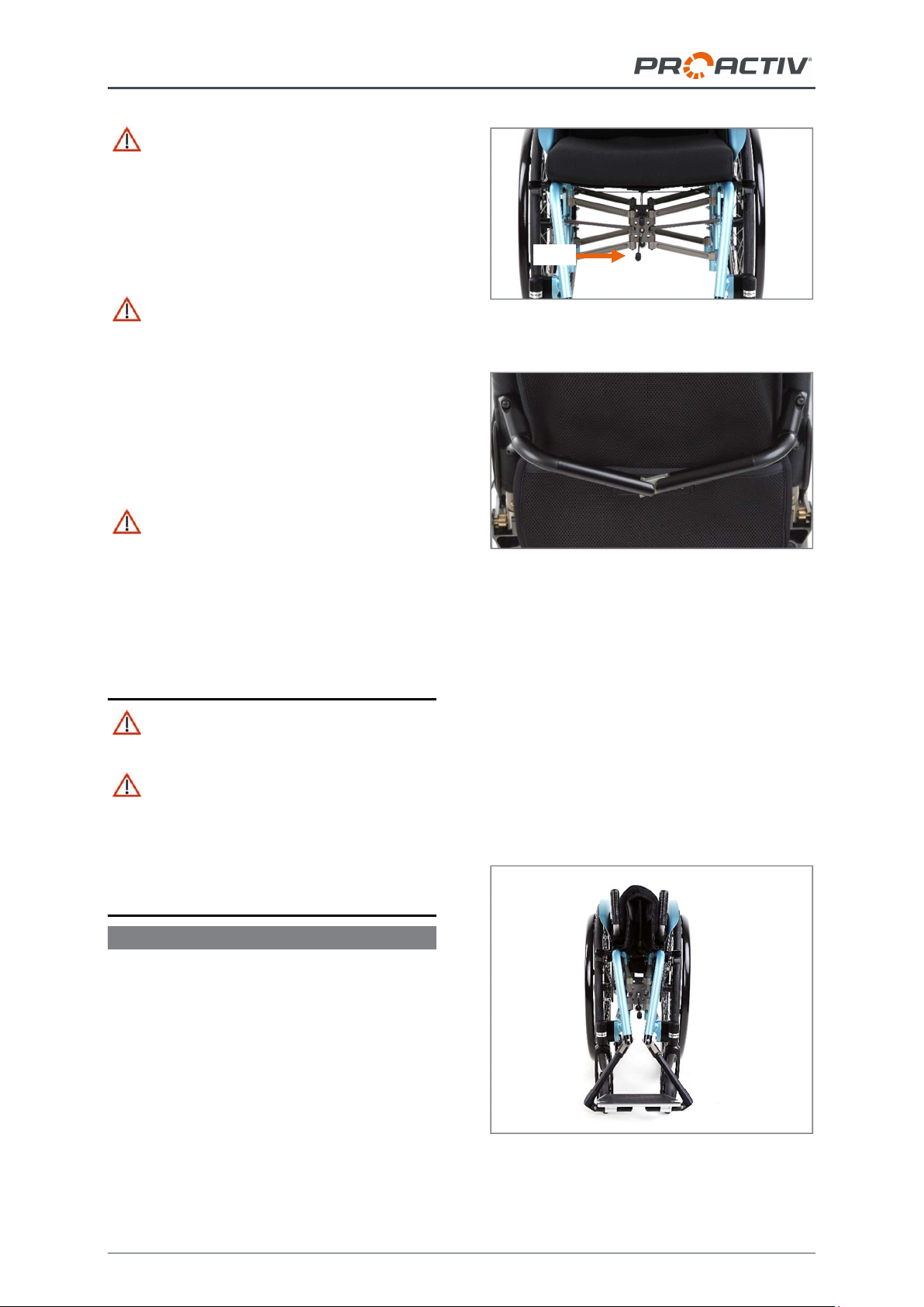
18.1.2 Turning the wheel plate by 180°
The wheel plate slots are worked eccentrically,
so that by turning the wheel plate by 180°, a
reduction of the seat height by approx.
1 cm is achieved.
Figure 11: Changing the seat height at the rear by
rotating the wheel plate by 180°.
Figure 12: M6 fixing screws on the wheel plate (view
from outer side of product, drive wheel removed)
3
cm
Drive wheel bushing
in the other wheel
plate slot
Outer steel
locking nut
Drive wheel bushing
Mounting the drive
wheel bushing in the
other wheel plate slot
Inner steel
locking nut
Wheel plate
turned by 180°
Wheel plate in the
initial position
1
cm
M6 fixing screws with
washers
TRAVELER usage instructions
16
Figure 13: M6 nuts on the wheel plate (view from
the inner side of the product, drive wheel removed)
1. Remove the wheel plates on both sides by
unscrewing the four M6 fixing screws (AF
5 mm) with the M6 nuts (AF 10 mm).
2. Then turn the wheel plate by 180° and po-
sition it behind the same frame holes as
before. Ensure that you mount the track
spacers and the camber wedges (between
the frame and the wheel plate, see Fig. 71
and 74) exactly as they were installed ex-
factory upon delivery (they must not be ro-
tated with the wheel plate). In addition, the
wheel plate can be mounted ex-factory on
the inside or outside of the frame. Again,
make sure that you re-mount the wheel
plates as they were ex-factory upon deliv-
ery.
3. Now reattach the M6 fixing screws (AF
5 mm) with M6 nuts (AF 10 mm) and
tighten to 7 Nm. Ensure that both washers
are reinstalled on each screw.
4. Then the drive wheel bushing is mounted
in the other slot. Observe the instructions
in Chapter 18.1.1.
18.1.3 Mounting the wheel plate in the
other frame holes
If the wheel plate is mounted in the initial
position in the lower frame holes, the seat
height can be reduced by 2 cm by mount-
ing it in the upper frame holes.
If the wheel plate is mounted in the initial
position in the upper frame holes, the rear
seat height can be increased by 2 cm by
mounting it in the lower frame holes.
Figure 14: Changing the seat height at the rear by
moving the wheel plate in the frame holes
To remove and attach the wheel plates, refer
to the information in Chapter 17.1.2. When re-
attaching the wheel plates, use the other frame
holes.
Figure 15: Frame holes (view from outer side of
product, drive wheel removed)
18.1.4 Summary
Figure 16: Example of initial position for adjustment
Additional frame holes
Drive wheel bushing in the lower slot
Wheel plate in the lower frame holes
M6 nuts with washers
2
cm
Frame holes
Wheel plate moved to
the other frame holes

TRAVELER usage instructions
17
For the seat height adjustment, as in the initial
position shown in the previous figure, the fol-
lowing steps can be taken:
1 cm reduction of the rear seat height: Rota-
tion of the wheel plate by 180° & moving the
drive wheel bushing back into the lower wheel
plate slot
2 cm reduction of the rear seat height: Mov-
ing of the wheel plate into the upper frame
holes
3 cm reduction of the rear seat height: Mov-
ing of the drive wheel bushing into the upper
slot of the wheel plate
4 cm reduction of the rear seat height: Rota-
tion of the wheel plate by 180° (drive wheel
bushing remains in the upper wheel plate slot)
5 cm reduction of the rear seat height: Mov-
ing of the wheel plate into the upper frame
holes & moving of the drive wheel bushing into
the upper wheel plate slot
6 cm reduction of the rear seat height: Rota-
tion of the wheel plate by 180° & moving of the
wheel plate into the upper frame holes (drive
wheel bushing remains in the upper wheel
plate slot)
If the wheel plate is initially mounted in the up-
per frame holes and/or the drive wheel bushing
is mounted in the upper slot, the seat height
can also be raised.
To raise the seat height even further, 3-slot
wheel plates are available. Here, the drive
wheel bushing can be mounted in the lowest
slot of the wheel plate and thereby achieve a
3 cm increase of the rear seat height.
Figure 17: 2-slot wheel plate and 3-slot wheel plate
18.1.5 General instructions
When changing the rear seat height each time:
the brakes must be readjusted (see Chap-
ter 26).
the caster wheel axles must be readjusted
(see Chapter 23.4).
the backrest angle may have to be reposi-
tioned (see Chapter 19.1.3).
make sure that there is sufficient ground
clearance under the footrest. Experience
shows that this should not be less than
4 cm (see Chapter 24).
if necessary, the height of the anti-tipping
support may have to be readjusted (see
Chapter 25.3).
18.2 Adjusting the seat height at the
front / angle of seat
If the seat height has to be adjusted, the angle
of the seat or the front seat height can be ad-
justed. This setting is carried out via the posi-
tion of the caster wheels in the caster wheel
fork and the caster fork size.
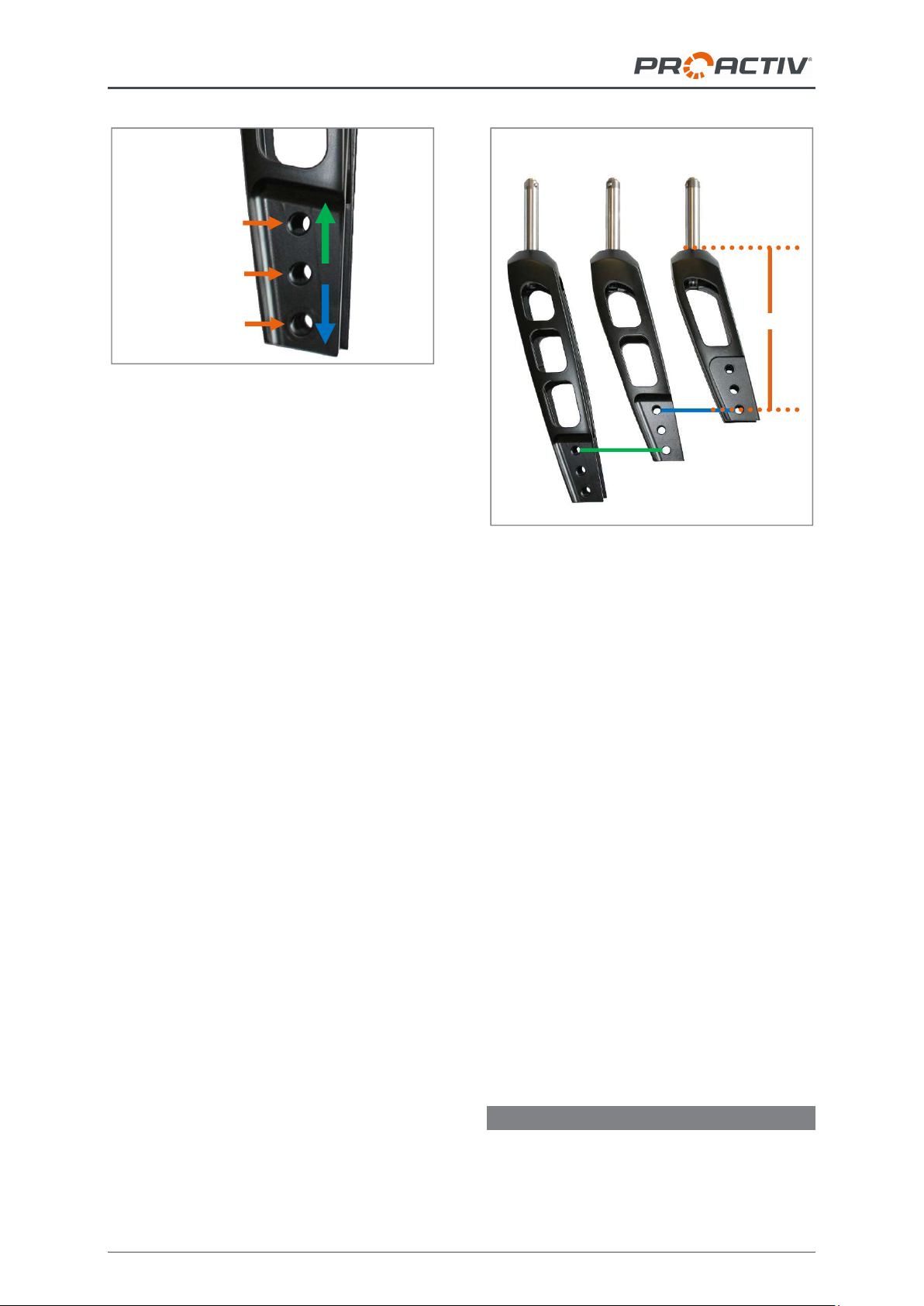
18.2.1 Adapting by positioning the caster
wheels in the caster fork
Adjusting the front seat height or angle of seat
can be carried out via the positioning of the
caster wheel in the caster fork. Generally, the
caster forks have three possible positions that
can be used to change the front seat height in
steps of 15 mm.
If the seat inclination or the front seat
height are to be increased, the caster
wheel is mounted in a lower position in the
caster fork.
If the seat inclination or the front seat
height are to be reduced, the caster wheel
is mounted in a higher position in the
caster fork.
TRAVELER usage instructions
18
Figure 18: Three positions in the caster fork for posi-
tioning the caster wheel and its effect on the front
seat height
The instructions for disassembly and assembly
of the caster wheels can be found in Chapter
23.1.
18.2.2 Adaptation by replacing the caster
fork
If the adjustment range of the existing caster
fork is insufficient, the next larger or smaller
one can be used.
In doing so, the bottom position of the fork size
1 is equivalent to the top position of fork size 2
and the bottom position of fork size 2 to the top
position of fork size 3.
Figure 19: Caster fork sizes with marking of the
same seat height settings with different caster fork
sizes
The instructions for replacing the caster forks
can be found in Chapter 23.3.
18.2.3 General instructions
When changing the angle of seat or front seat
height each time:
the caster wheel axles must be readjusted
(see Chapter 23.4).
the backrest angle may have to be reposi-
tioned (see Chapter 19.1.3).
make sure that there is sufficient ground
clearance under the footrest. Experience
shows that this should not be less than
4 cm (see Chapter 24).
if necessary, the height of the anti-tipping
support may have to be readjusted (see
Chapter 25.3).
18.3 Adjusting the tipping point
Optimum product tipping behaviour is
achieved when the axle mount of the drive
wheels is close to the body centre of gravity. A
Top position
Middle position
Bottom position
Angle of
seat/front
seat height
increase
Angle of
seat/front
seat height
reduce
Size 3
185 mm
Size 2
155
mm
Size 1
125 mm
125
mm

TRAVELER usage instructions
19
product adjusted like this can be driven with lit-
tle effort and it also makes it possible to man-
age a slightly uneven surface or edges by tip-
ping slightly. Driving on both drive wheels (do-
ing a wheelie) is relatively easy to learn. Inex-
perienced wheelchair users must be prevented
from tipping over backwards by means of anti-
tipping supports. In any case, the setting
should be made to suit the wheelchair user's
individual requirements and abilities to ensure
safe operation.
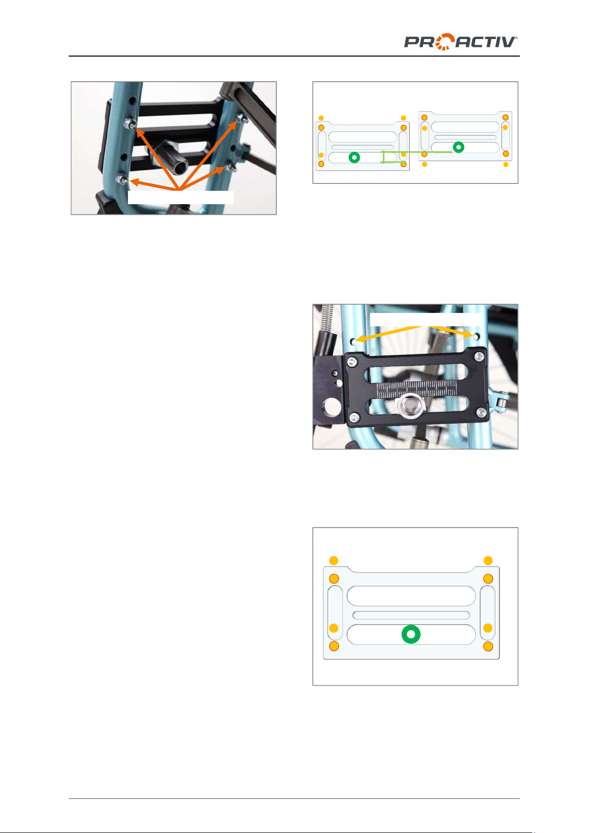
Setting the tipping point is carried out by
changing the positioning of the drive wheel
bushings in the wheel plates.
Figure 20: Wheel plate and drive wheel bushing
(view from outer side of product, drive wheel re-
moved)
1. To adjust the tipping position, first remove
the drive wheels via the quick release ax-
les (see Chapter 22.1), so that you have
direct access to the wheel plates. Then
proceed as follows: Loosen the inner steel
fastening nuts (AF 30 mm) on both sides.
Figure 21: Outer steel locking nut and drive wheel
bushing (view from outer side of product, drive
wheel removed)
Figure 22: Inner steel locking nut (view from inside
of product, drive wheel removed)
2. Now slide the drive wheel bushings along
the slots in the wheel plates to the desired
tipping point position. Make sure that the
two drive wheel bushings on the right and
left are in exactly the same tipping point
position. The scale on the front of the
wheel plates can be used as a guide.
Figure 23: Sliding the drive wheel bushing along the
slot in the wheel plate (view from outer side of prod-
uct, drive wheel removed)
Figure 24: Scale on the wheel plate
3. Then tighten the inner steel mounting nuts
(AF 30 mm) on the right and left to 70 Nm.
Outer steel locking nut
Drive wheel bushing
Sliding the drive wheel bushing
along the slot in the wheel plate
Scale on the wheel plate
Wheel plate
Drive wheel bushing
Inner steel
locking nut
Table of contents
Other Proactive Wheelchair manuals


