ruction Handbook Eco Twin
4.6
Operation and maintenance space requirements
4.7
•
Electrical connection by qualified personnel only.
•
Disconnect system from mains and prevent unintentional restart/reclosing.
•
Check the data on the motor
•
When connecting the motor, it is an imperative to heed the drive manufacturer's instructions and
the applicable regulations for electrical equipment (e.g. motor protection, main sw
•
Check the phase sequence for the direction of motor rotation prior to making the connection.
•
Screw pump are preferably operated on frequency converters or on
soft-
•
Provide emergency stop facilities to shut down the pump in the event of dangerous situations.
ViscoTwin_0_002 EN
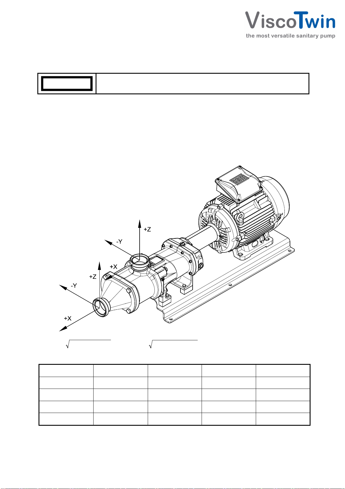
Operation and maintenance space requirements
•
Allow for free space around the pump (
drawing to provide for maintenance work without removing the pump. To
simplify installation, use fitting pieces and shut
•
In addition, plan free space for sufficient drive motor ventilation (
Danger to life through electric shock!
Electrical connection by qualified personnel only.
Disconnect system from mains and prevent unintentional restart/reclosing.
Check the data on the motor
When connecting the motor, it is an imperative to heed the drive manufacturer's instructions and
the applicable regulations for electrical equipment (e.g. motor protection, main sw
Check the phase sequence for the direction of motor rotation prior to making the connection.
Screw pump are preferably operated on frequency converters or on
-
stated on the type plate.
Provide emergency stop facilities to shut down the pump in the event of dangerous situations.
Operation and maintenance space requirements
Allow for free space around the pump (
drawing to provide for maintenance work without removing the pump. To
simplify installation, use fitting pieces and shut
In addition, plan free space for sufficient drive motor ventilation (
Danger to life through electric shock!
Electrical connection by qualified personnel only.
Disconnect system from mains and prevent unintentional restart/reclosing.
Check the data on the motor
When connecting the motor, it is an imperative to heed the drive manufacturer's instructions and
the applicable regulations for electrical equipment (e.g. motor protection, main sw
Check the phase sequence for the direction of motor rotation prior to making the connection.
Screw pump are preferably operated on frequency converters or on
stated on the type plate.
Provide emergency stop facilities to shut down the pump in the event of dangerous situations.
Operation and maintenance space requirements
Allow for free space around the pump (
drawing to provide for maintenance work without removing the pump. To
simplify installation, use fitting pieces and shut
In addition, plan free space for sufficient drive motor ventilation (
Danger to life through electric shock!
Severe or fatal injuries.
Electrical connection by qualified personnel only.
Disconnect system from mains and prevent unintentional restart/reclosing.
Check the data on the motor
type plate against mains voltage and frequency before connecting
When connecting the motor, it is an imperative to heed the drive manufacturer's instructions and
the applicable regulations for electrical equipment (e.g. motor protection, main sw
Check the phase sequence for the direction of motor rotation prior to making the connection.
Screw pump are preferably operated on frequency converters or on
-
high
stated on the type plate.
Provide emergency stop facilities to shut down the pump in the event of dangerous situations.
Operation and maintenance space requirements
Allow for free space around the pump (
drawing to provide for maintenance work without removing the pump. To
simplify installation, use fitting pieces and shut
In addition, plan free space for sufficient drive motor ventilation (
Danger to life through electric shock!
Severe or fatal injuries.
Electrical connection by qualified personnel only.
Disconnect system from mains and prevent unintentional restart/reclosing.
type plate against mains voltage and frequency before connecting
When connecting the motor, it is an imperative to heed the drive manufacturer's instructions and
the applicable regulations for electrical equipment (e.g. motor protection, main sw
Check the phase sequence for the direction of motor rotation prior to making the connection.
Screw pump are preferably operated on frequency converters or on
Provide emergency stop facilities to shut down the pump in the event of dangerous situations.
Operation and maintenance space requirements
Allow for free space around the pump (
→
→→
→
drawing to provide for maintenance work without removing the pump. To
simplify installation, use fitting pieces and shut
In addition, plan free space for sufficient drive motor ventilation (
Danger to life through electric shock!
Severe or fatal injuries.
Electrical connection by qualified personnel only.
Disconnect system from mains and prevent unintentional restart/reclosing.
type plate against mains voltage and frequency before connecting
When connecting the motor, it is an imperative to heed the drive manufacturer's instructions and
the applicable regulations for electrical equipment (e.g. motor protection, main sw
Check the phase sequence for the direction of motor rotation prior to making the connection.
Screw pump are preferably operated on frequency converters or on
Provide emergency stop facilities to shut down the pump in the event of dangerous situations.
drawing to provide for maintenance work without removing the pump. To
simplify installation, use fitting pieces and shut
-
In addition, plan free space for sufficient drive motor ventilation (
Severe or fatal injuries.
Disconnect system from mains and prevent unintentional restart/reclosing.
type plate against mains voltage and frequency before connecting
When connecting the motor, it is an imperative to heed the drive manufacturer's instructions and
the applicable regulations for electrical equipment (e.g. motor protection, main sw
Check the phase sequence for the direction of motor rotation prior to making the connection.
Screw pump are preferably operated on frequency converters or on
Provide emergency stop facilities to shut down the pump in the event of dangerous situations.
drawing to provide for maintenance work without removing the pump. To
In addition, plan free space for sufficient drive motor ventilation (
→
→→
→
Disconnect system from mains and prevent unintentional restart/reclosing.
type plate against mains voltage and frequency before connecting
When connecting the motor, it is an imperative to heed the drive manufacturer's instructions and
the applicable regulations for electrical equipment (e.g. motor protection, main sw
Check the phase sequence for the direction of motor rotation prior to making the connection.
Provide emergency stop facilities to shut down the pump in the event of dangerous situations.
Page 4-4
drawing to provide for maintenance work without removing the pump. To
type plate against mains voltage and frequency before connecting
When connecting the motor, it is an imperative to heed the drive manufacturer's instructions and
Check the phase sequence for the direction of motor rotation prior to making the connection.
Provide emergency stop facilities to shut down the pump in the event of dangerous situations.
Manual ViscoTwin 104-xx 3A