PROCET PT-PEX02GB User manual

PT-PEX02GB PoE Extender
www.procetpoe.com
Quick Installation Guide

The symbol indicates that the product should not be discarded as
unsorted waste but must be sent to separate collection facilities for recovery
Copyright ©2022Creative Lianjie Network Technology Co.Ltd
This document belongs to PROCET company. It is not allowed to reproduce and
modify without the original author's permission. It is PROCET's policy to
improve its products as new technology, components, software, and firmware
at any time. PROCET, therefore, reserves the right to change specifications
without prior notice. Please follow WEEE (Waste Electrical and Electronic
Equipment) disposal instructions for old electronic products.
Please do not dispose of the old product in your general household waste bin.
All rights reserved.
and recycling.
Declaration
Declaration

The installation Guide for PT-PEX02GB and mainly introduces the hardware
specification, installation methods, and precautions of the installation. There may be
differences in the appearance and configuration from other models. All product
images in this manual are for illustration purposes only and may differ from the
actual product.
This manual includes the following chapters:
1. Product Introduction. Including the basic functions and specification of
PT-PEX02GB, as well as the product appearance and applications introduction.
2. Installation Introduction. Introducing the preparation work and precautions
before installing the product.
3. Product Installation. Two methods of product installation.
Overview
Network Engineers
Network Administrators
Field Technicians
Overview
For whom

3.1 Wall mounting..................................................................06
3.2 Slot-fasten mounting.....................................................08
3.3 Grounding..........................................................................09
3.4 Inspection..........................................................................11
The table of contents
2.1 Package contents..............................................................04
2.2 Installation toolkit.............................................................04
1.1 Introduction....................................................................01
1.2 Appearance.....................................................................01
1.3 Specification....................................................................03
2.3 Inspection............................................................................04
Table of contents
1 Introduction 01
2 Installation preparation 04
3 Installation 06

1.
Introduction 01
The mounting slot
Introduction
1.1 Introduction
1.2 Appearance
Upper view
PT-PEX02GB is an industrial-rated PoE Extender with two PoE output ports,
specially designed for complex backhaul and networking applications.
Enclosed in a high-impact metal shell. The 3 ports 10/100/1000Mbps includes:
1 x PoE-powered input port with 802.3bt/PoE++ at 60W or higher of 95W(Max
) and 2 x PoE output ports with 6KV (10/700us) surge protection. Each output
port delivers 30W(Max) power for remote two PDs, totaling up to 60W.
PoE Input port requiring more power which is powered by ultra 802.3bt PoE+
+ works with an input voltage of 44- 57Vdc and operates under -40℃to +65
℃. Equipped detecting chip inside which will make the PoE identification
handshake with IEEE802.3af/at/PoE+ PDs, such as wireless APs, IP cameras,
base stations, Microwave radio, and other PoE power Ethernet backhaul
devices.For planning purposes, the total effective distance from Ultra PoE to
PDs is 200 meters over CAT5e/CAT6 cables without local power.
This product features one PoE input port and two PoE output ports, as
well as two mounting tabs on either side. It can be used an outdoor PoE
extenderby cover with a waterproof case or as a standard dual-port
PoE network switch.
1-1 Upper view
2.5mm
screw
mounting
hole

1-2
02 Introduction
1-3 Front view
Side view
Front view
Body
screws
Side view
PoE Input
Port
RJ45 Data
Indicator
PoE Output Port1
PoE Output Port
RJ45 Power
Indicator
GND Terminal
2

Introduction 03
1.3 Specification
Items Status
Solid
Flashing
Solid
Flashing
OFF
Indicators Display:
System abnormal or power off
Data transmitting
Good connection
Detection load
Good Power
Description
Items
Input
4/5(+),7/8(-),3/6(+),1/2(-)
55V / 0.55A * 2Po
Power pins
s(Total 60W)
3/6(+), 1/2(-)
Description
Data
indicator
PoE load
indicator
Data speed
Output
Power pins
Work temp.
Operating
Operating
Humidity
Altitude
Storage
Storage
Temp.8
Humidity
-40℃ to 65℃
20%-80%,non-condensation
Up to 2000 meters
-40℃ to 85℃
10%-95%,non-condensation
IEEE802.3 / IEEE802.3u / IEEE802.3ab
98.5mm×70.27mm×29.7mm (207.8g)
10/100/1000BASE-TX Cat5 or above UTP(≤328 feets)
CE FCC
IP40
Regulatory
Network
Protocol
IP Rated
Compliance
Dimensions
10/100/1000Mbps
44-57V 1.5A Max
EN 55032:2015/A11:2020
EN 55035:2017/A11:2020
EMC
Green Light
Yellow Light
Media
support
PoE Surge
Protection
Protected line:1,2,3,4,5,6,7,8
Common mode surge protection(10/700us): 6kV
Differential mode surge protection (10/700us): 1.5KV

Caution:
Please use PoE power supply equipment that complies
with corresponding standard to connect this product.
04 Installation Preparation
2.Installation preparation
2.1 package contents
2.2 Installation
Open the box of the PT-PEX02GB and carefully unpack it, the box should
contain the following items:
toolkit
These tools may be needed during equipment installation and should
be prepared by yourself: level ruler, marking pen, craft knife,
wires tripper, network pliers, impact drill, different matching drillbits,
rubber hammer, cross screwdriver,wrench, ladder, etc.
2.3 Inspection
2.3.1 Connect the device to a PoE switch and check the PWR LED
toensure proper function before installation.
2.3.2 When using standard PoE power supply, the Ethernet cable
needs to be connected to the PoE PD, such as a PoE camera.
as shown in Figure 2-1
!
PT-PEX02GB Ground lug
Wire&2.5
screw
Operation manual

Installation preparation 05
2-1 Device connection
PoE Switch
PT-PEX02GB
PD 01
PD 02
Connect PoE IN to PoE switch, the yellow data indicator and green
power indicator are on, while the connection is done.
Now you can connect the extender with PDs in two PoE output port.
The yellow data indicator and green power indicator are on, and the
PDs are successfully connected.
Caution:
We recommend to use Cat5 or higher UTP/STP cablesf or
100 Base-TX Ethernet;
We recommend to use Cat5e or above UTP/STP cables
To ensure better lightning protection for outdoor PD, it is
recommended to use PROCET Ethernet surge protection products. For
more information, please visit http://www.procetpoe.com
for 1000Base-T or 2.5GBase-T Ethernet.
!
PoELAN
OLink
POWER

the hole
diameter
8mm
06 Installation
3.Installation
3.1 Wall mounting
The device will be fixed on the wall with screw into the poles, and
the hole diameter should be between 8mm to10mm.
3.1.1Mark the screw hole positions with marking pens.
As showed in3-1.
This product is safe to use for slot-fasten mounted and wall-mounted installation.
3-1 Marks for holes
wall

Installation 07
3.1.2Drill an 8mm diameter hole at the marked position and fix the
expansion bolt into the hole by hitting it with a rubber hammer.
3.1.3Fix the product with screws and tighten them into the expansion
bolts.
As showed in3-2.
3-2
Installation
Caution in drilling process:
· keep the drill bit perpendicular to the wall surface, hold the drill
handle tightly with both hands, maintain a steady direction to avoid
shaking and damaging thewall or causing the hole to tilt.
· If the wall is too hard and smooth for the drillbit to locate, use a
center punch to make an indentation at the hole position to help
guide the drillbit.
· The depth of each hole should be consistent.
Wall
Self-tapping screws
Product mounting holes
Expansion bolts

3.2 Slot-fasten mounting
3-3
08 Installation
Bolt depth
3-4 Slot-fasten mounting
Bolt depth≥60mm
Wall with screw
Product slot
Use the slot-fasten mounting to fix the product on the wall with screws.
3.2.1Loosen the screws and put the product slot into the screw.
As showed in 3-4.

3-5 Slot-fasten installation
Installation 09
3.3 Grounding
PROCET outdoor dual-ports splitter PT-PEX02GB-OT has the
followinggrounding solutions for reference duringconstruction:
If the installation is in the computer room, it can be connected to
the dedicated grounding busbar in the room. The grounding busbar
is a connecting conductor between the grounding bodies of the
building, such as flat iron, flat steel, nano material conductors,
copper-clad steel, etc. Pls refer to the figure3-6.
Wall with screw
3.2.2 Make sure the slot is fixed to the screws tightly and tighten
the screws.
As showed in 3-5.

10 Installation
3-6 Grounding
GND Terminal
2.5MM screw
Grounding busbar
Caution:
Use a galvanized metal pipeburied underground at
a depth of one meter or more, such as a water or
sewagepipe,as an emergency grounding if no other
grounding environment is available.
!
For the safety of personnel and equipment in an environment
without dedicated grounding equipment, a simple grounding
device can be constructed as follows:
a. Prepare a 6mm 2 grounding wire or a braided soft copper wire.
b. Prepare a copper tube or angleiron, or other metal tube, bury it
underground to a depth of one meter or more as a grounding
electrode.
c. Use the grounding wire to connect the external grounding
terminal of the product to the metal tube.(or angle iron)

3.4 Inspection after installation
Inspect the installed equipment before putting it into operation:
• Make sure the PoE switch is compliant with our product.
Installation 11
3-7 Simple grounding
Ground
GND Terminal
2.5MM screw
2200
MM
soil
• Make sure the Ethernet cable connection is correct.
Make sure all connections are correct, and turn on the power,
inspect all the indicators.

Qualication Card
PASS
Creative Lianjie Network Technology Co.Ltd
www.procetpoe.com
Other manuals for PT-PEX02GB
1
Other PROCET Extender manuals
Popular Extender manuals by other brands

Belden
Belden thinklogical TLX Series product manual

DataBay
DataBay KVME-300 user manual
Proscend
Proscend VDSL2 LAN Extender user manual
Visus
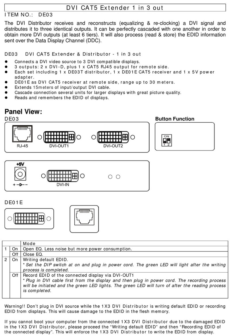
Visus DE03T quick start guide

TX RX Systems
TX RX Systems Signal Booster II 61-65-50 Series Installation and operation manual

Williams Sound
Williams Sound DLT 300 user manual


