Procom QEB100 User manual

Questions, problems, missing parts? Before returning to your retailer, call
our customer service department at 1-866-573-0674, 7:30 am - 4:15 pm CST,
QEB100 BLOWER ACCESSORY
INSTALLATION INSTRUCTIONS
WARNING: ELECTRICAL GROUNDING INSTRUCTIONS This
appliance is equipped with a three-prong (grounding) plug for your
protection against shock hazard and should be plugged directly into
a properly grounded three-prong receptacle.
Spanish/Español
Page 17
www.usaprocom.com 200070-01E
2
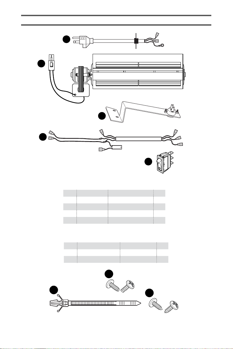
Parts included with this kit
Item Part No. Description Qty
A XB001-01 Power Cord 1
B XB002-01Q Blower 1
C XB003-01 Temperature Sensor 1
D XB004-01Q Connect Wire 1
E PF06-0400-A Rocker Switch 1
PACKAGE CONTENTS
A
B
C
AA
BB
D
E
If any of these pieces are missing or damaged, contact the dealer where you purchased this
kit or ProCom Heating, Inc. at 1-866-573-0674 for referral information.
CC
Hardware
Item Part No. Description Qty
AA GB/T 845-4.2*9.5F M4.2x9.5 Screw 6
BB VL057-01 Cable Tie 2
CC GB/T 845-4.2*9.5 M4.2x9.5 Screw 4

www.usaprocom.com 3200070-01E
SAFETY
IMPORTANT: Read all instruc-
tions and warnings carefully
before starting installation. Fail-
ure to follow these instructions
may result in a possible electric
shock, re hazard and will void
the warranty.
• Read all instructions before using this ap-
pliance.
• If possible always unplug this appliance
when not in use.
• Do not operate any heater with a damaged
cord or plug or after the appliance malfunc-
tions, has been dropped or damaged in any
manner.
• Any repairs to this appliance should be
carried out by a qualied service person.
• Under no circumstances should this ap-
pliance be modied. Parts having to be
removed for servicing must be replaced
prior to operating this appliance again.
• Do not use outdoors.
• Never locate this appliance where it may
fall into a bathtub or other water container.
• Do not run cord under carpeting. Do not
cover cord with throw rugs, runners or the
like. Arrange cord away from trac areas
and where it will not be tripped over.
• To disconnect this appliance, turn controls
to the o position, then remove plug from
outlet.
• Connect to properly grounded outlets only.
• This appliance, when installed must be
electrically grounded in accordance with
local codes, with the current CSA C22.1
Canadian Electrical Codes or for USA
installations, follow local codes and the
National Electric Code, ANSI/NFPA No. 70.
• Do not insert or allow foreign objects to
enter any ventilation or exhaust opening
as this may cause an electric shock, re
or damage the appliance.
• To prevent possible re, do not block air
intakes or exhaust in any manner.
• Use this appliance only as described in this
manual. Any other use not recommended
by the manufacturer may cause re, electric
shock or injury to persons.
• Avoid the use of an extension cord because
of the risk of overheating the cord and the
risk of re. Extension cords are for tempo-
rary use only. If an extension cord must be
used, it must be UL/CSA certied, rated
at 10A (1250W), 125V maximum with 16
AWG minimum and constructed of two
current carrying conductors with ground. A
heavy duty extension cord with the shortest
length possible for the connection is recom-
mended and must not be longer than 50 ft.
(15.2 m). Do not coil or cover the extension
cord.
www.usaprocom.com 200070-01E
4
PREPARATION
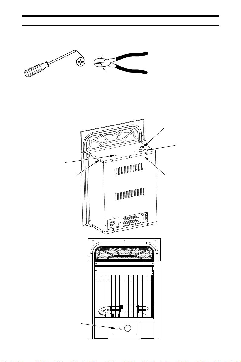
Tools Required
• Phillips Screwdriver
• Wire Cutter
This blower contains assembly instructions for ED series.
For the CRHQD250T, CRHSD25RT, BD23 series, Q stove, PCSD25RT series and FBD400
series see page 8 - 13.
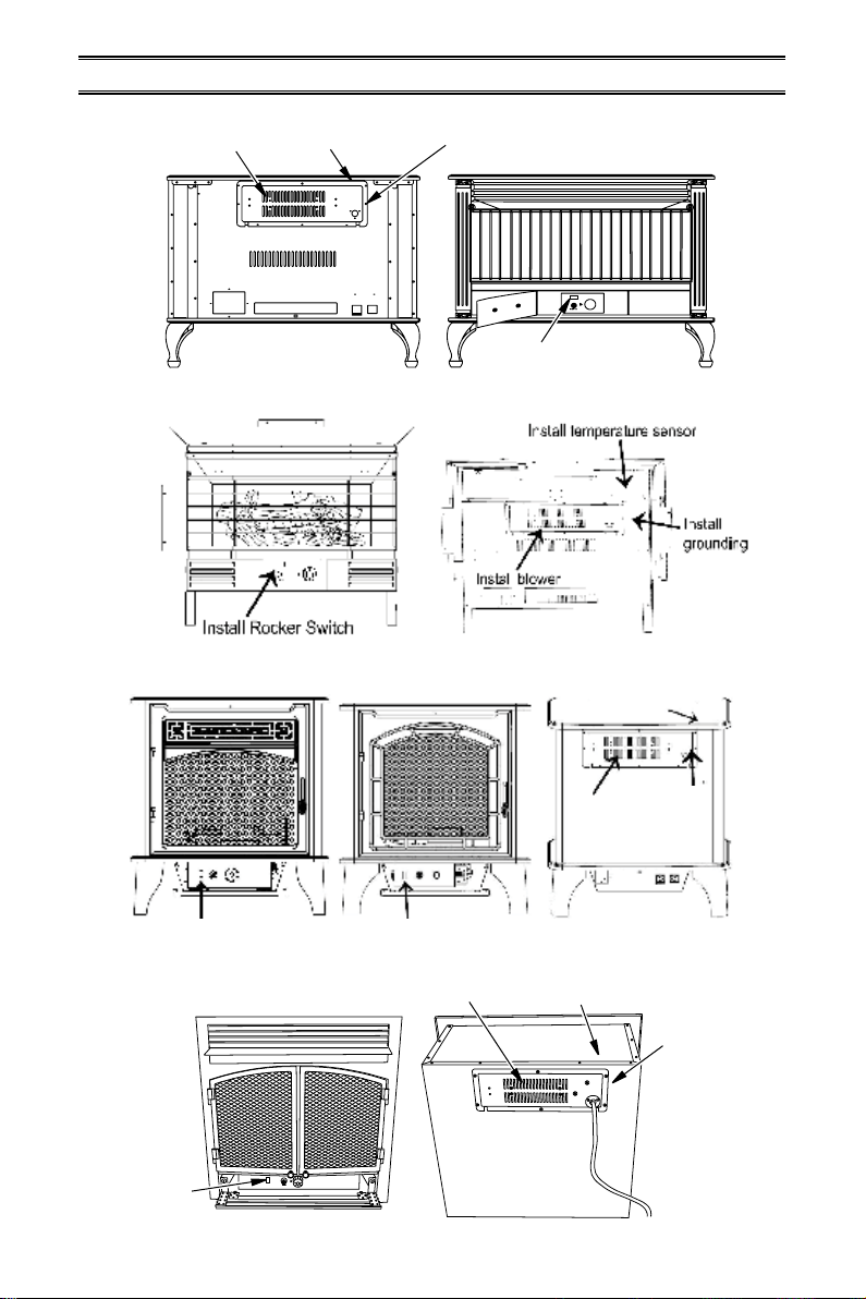
BLOWER INSTALLATION ED SERIES
Install
Rocker
Switch
Install
Blower
Top Cover
Install Power
Cord and
Grounding
Terminal
Protection Tab
Install Temperature
Sensor to Back
of Firebox after
Removing Top Cover
www.usaprocom.com 5200070-01E
AA
WARNING: Before installing
the blower, be certain to turn o
the unit, and allow time for unit
to cool down.
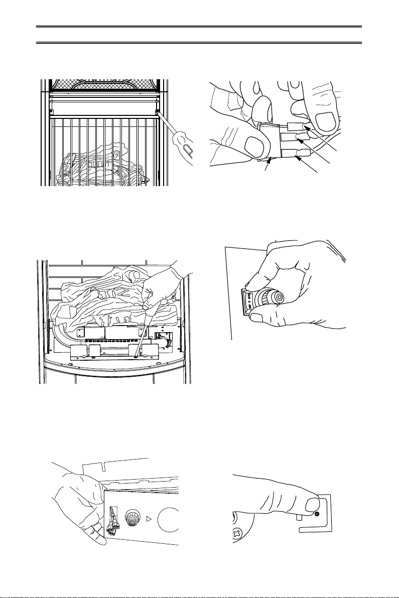
1. Unscrew and remove top cover of the
replace (see Figure 1).
Figure 1 - Remove Fireplace Top Cover
Figure 2 - Installing Power Cord
Figure 3 - Attaching Blower to Top Cover
2. Attach the power cord to the replace top
cover with 3) M4.2X8 screws (AA) (see
Figure 2).
3. Attach the blower assembly to the top
cover with 4) M4.2X8 screws (CC) (see
Figure 3).
AA
CC
INSTALLATION -ED SERIES
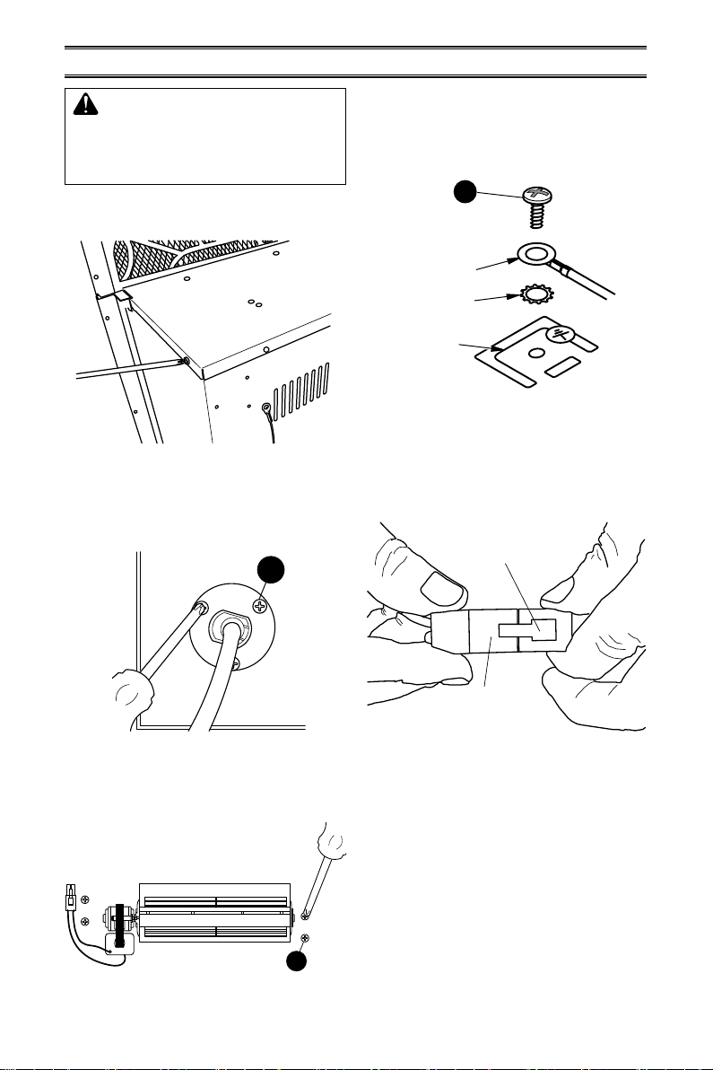
Figure 4 - Installing Grounding Terminal
to Top Cover
4. Attach the grounding terminal to top cover
with 1) M4.2X8 screw (AA). Refer to wiring
diagram, page 15. Be sure to insert the
gasket between the protection tab and
the grounding terminal (see Figure 4).
Figure 5 - Connecting Blower Wire to
Wire Connector
5. Insert the blower connector (male port)
into the female port on the wire connector.
This protects the jacket in the replace
(see Figure 5).
Grounding
Terminal
Gasket
Protection Tab
Male Port
Female
Port
www.usaprocom.com 200070-01E
6
T1
T2
Figure 9 - Installing Temperature Sensor
Figure 10 - Feeding Wire Harness
Figure 11 - Temperature Sensor Wires
9. Attach temperature sensor to the back of
the rebox with 2) M4.2X8 screws (AA)
(see Figure 9).
10. Insert the wires marked with AUTO, OFF
and MAN into wire slot in the right corner.
Feed them as close to the bottom of the
rebox as possible (see Figure 10).
MAN
OFF
AUTO
11. Connect two black and yellow wires (fe-
male ports) marked T1 and T2 with the
two male ports on the temperature sensor
(see Figure 11).
INSTALLATION -ED SERIES
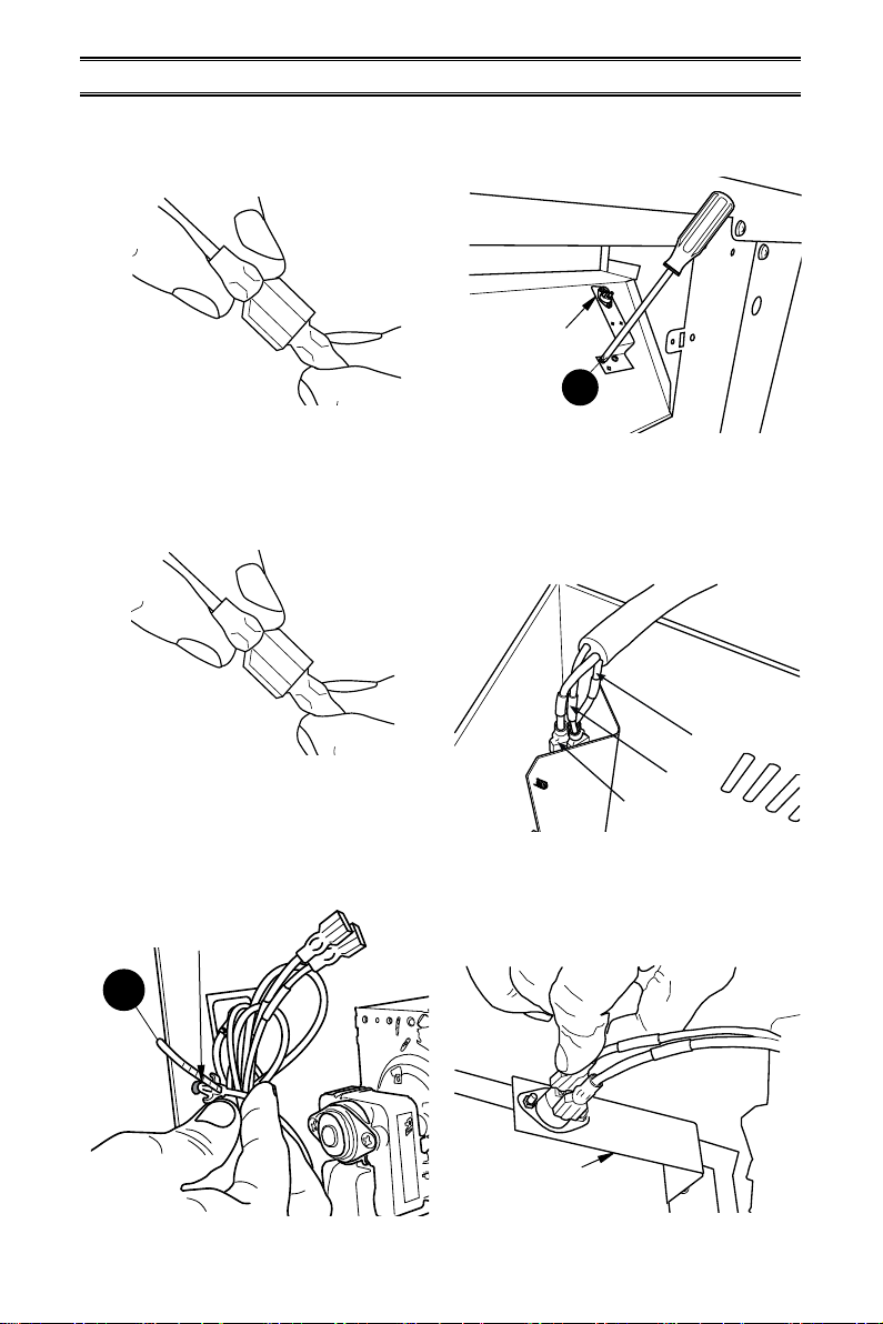
Figure 7 - Connecting P2 Wires
Figure 6 - Connecting P1 Wires
Figure 8 - Securing Blower Wires
P2
6. Insert the female port, which is on the
white power supply wire (marked with P1),
into the corresponding male port (marked
with P1), (see Figure 6).
7. Insert the male port, which is on the black
power supply wire (marked with P2), into
the corresponding female port (marked
with P2), (see Figure 7).
P1
8. Bundle the wiring with the cable tie (BB).
Attach cable tie to the top panel through
the hole as shown in Figure 8. This is to
avoid any heat damage to the insulation
board.
BB
Temperature
Sensor
Install End of Cable
Tie Through Hole
AA
Temperature
Sensor
www.usaprocom.com 7200070-01E
Figure 12 - Removing Grill from Fireplace
Figure 13 - Removing Screws from
Control Panel
Figure 14 - Inserting Rocker Switch Wires
12.
Remove 2 screws securing grill to stove
front. Carefully set grill aside (see Fig-
ure 12).
AUTO
OFF (O)
MAN
Rocker Switch
Figure 15 - Connecting Wires to Rocker
Switch
Figure 16 - Installing Rocker Switch
Figure 17 - Protection Tab on Top Cover
13. Remove logs and carefully set aside. Note
log placement before removing.
14. Remove 2 screws securing control panel.
Pull the control panel out without discon-
necting the ignitor wire (see Figure 13).
IGNITOR
15. Feed the AUTO, OFF, MAN connectors
through the rocker switch hole on the left
side of the control panel (see Figure 14).
16. Connect the AUTO, OFF, MAN wires to
the three corresponding male tabs on the
rocker switch (see Figure 15).
INSTALLATION -ED SERIES
17. Push the rocker switch into the control
panel (see Figure 16).
18. Reattach the control panel with two screws
removed in step 14 (see Figure 13).
19. Reinstall logs according to original layout.
Refer to owner's manual for log place-
ment.
20. Install grill with 2 screws removed previ-
ously (see Figure 12).
21. Replace top cover (see Figure 1, page 5).
22. Push the protection tab to embed it into
the surface of the top cover (see Figure
17).
www.usaprocom.com 200070-01E
8
CRHQD250T and Q Series
INSTALLATION
Install Rocker Switch
Install
Rocker
Switch
Install Rocker Switch Install Rocker Switch
Install Blower
Install Blower
Install
Blower
Install Wiring and
Grounding Terminal
Install
Wiring and
Grounding
Terminal
Install
Wiring and
Grounding
Terminal
Install Temperature
Sensor
Install Temperature
Sensor
BD23 Series
PCSD25RT and CRHSD25RT
FBD400 Series
Install Temperature
Sensor
www.usaprocom.com 9200070-01E
AA
AA
CC
INSTALLATION -CRHQD250T, Q SERIES, B23 SERIES,
PCSD25RT, CRHSD25RT AND FBD400 SERIES
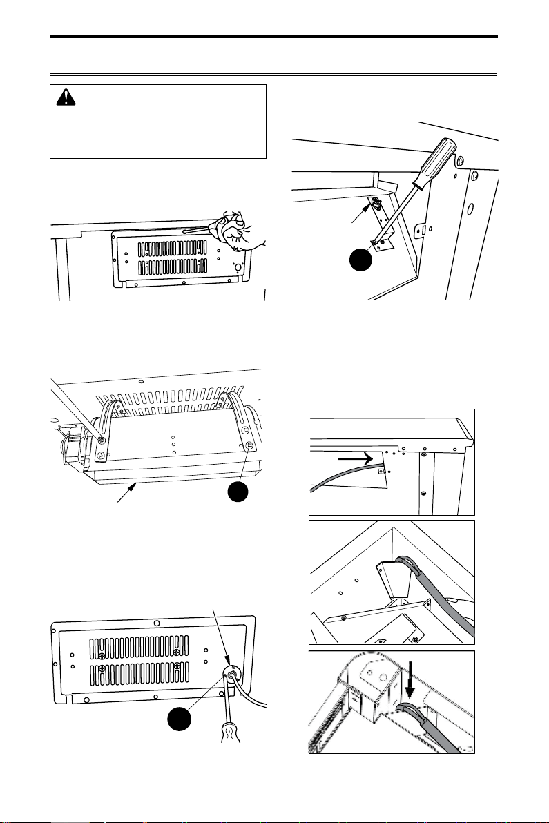
WARNING: Before installing
the blower, be certain to turn o
the unit, and allow time for unit
to cool down.
1. Remove screws securing blower access
panel to back of stove (see Figure 18).
Place screws in a safe location.
Blower
Temperature
Sensor
Power Cord
Figure 18 - Removing Blower Access Panel
Figure 19 - Attaching Blower to Blower
Access Panel
Figure 20 - Attaching Power Cord to
Blower Access Panel
Figure 21 - Attaching Temperature
Sensor to Firebox
Figure 22 - Feeding Wire Harness
2. Attach blower to the inside of the blower
access panel with 4) M4.2X8 screws (CC)
(see Figure 19).
3. Attach the power cord to the outside of
the blower access panel with 3) M4.2X8
screws (AA) (see Figure 20).
4. Attach the temperature sensor to the back
of the rebox with 2) M4.2X8 screws (AA)
(see Figure 21).
5. Insert wires marked with AUTO, OFF and
MAN into wire slot in the right corner of
the stove body. Feed the wires down and
as close to the bottom of the stove as
possible (see Figure 22).
PCSD25RT Only

www.usaprocom.com 200070-01E
10
AA
INSTALLATION -CRHQD250T, Q SERIES, B23 SERIES,
PCSD25RT, CRHSD25RT AND FBD400 SERIES
6. Connect two black and yellow wires (fe-
male ports) marked T1 and T2 with the
two male ports on the temperature sensor
(see Figure 23).
Figure 23 - Temperature Sensor Wires
T1
T2
Temperature
Sensor
Grounding
Tab
Grounding
Tab
7. Insert the female port, which is on the
white power supply wire (marked with P1),
into the corresponding male port (marked
with P1) (see Figure 24).
Figure 25 - Connecting P2 Wires
Figure 24 - Connecting P1 Wires
P2
P1
8. Insert the male port, which is on the black
power supply wire (marked with P2), into
the corresponding female port (marked
with P2) (see Figure 25).
9. Insert the blower connector (male port)
into the female port on the wire connector.
This protects the jacket in the replace
(see Figure 26).
Figure 26 - Connecting Blower Wire to
Wire Connector
Figure 27 - Attach Grounding Wire
Figure 28 - Adjusting Grounding Tab
10. Attach the grounding terminal to the tab
on the right side of the blower access hole
with 1) M4.2X8 screw (AA) (see Figure
27).
11. Push grounding tab inwards (approxi-
mately 60 degrees) (see Figure 28).
Male Port
Female
Port
Table of contents


