Procopi Aquareva SL-119-MR Operating instructions

2014/03 - Indice de révision : A - Code : 0025110
1/32
SL-119-MR
SB-118-MR
NOTICE D’INSTALLATION ET CONSEILS D’UTILISATION
INSTRUCTIONS FOR INSTALLATION AND RECOMMENDATION
MONTAgEANLEITUNg UND EMpFEhLUNgEN
INSTRUCCIONES DE MONTAjE y CONSEjOS DE UTILIzACIóN
P
R
O
C
O
P
I
*
B
R
E
V
E
T
FRANçAIS: pAgE 1 ENgLISh: pAgE 9 DEUTSCh : SEITE 17 ESpAÑOL : págINA 25
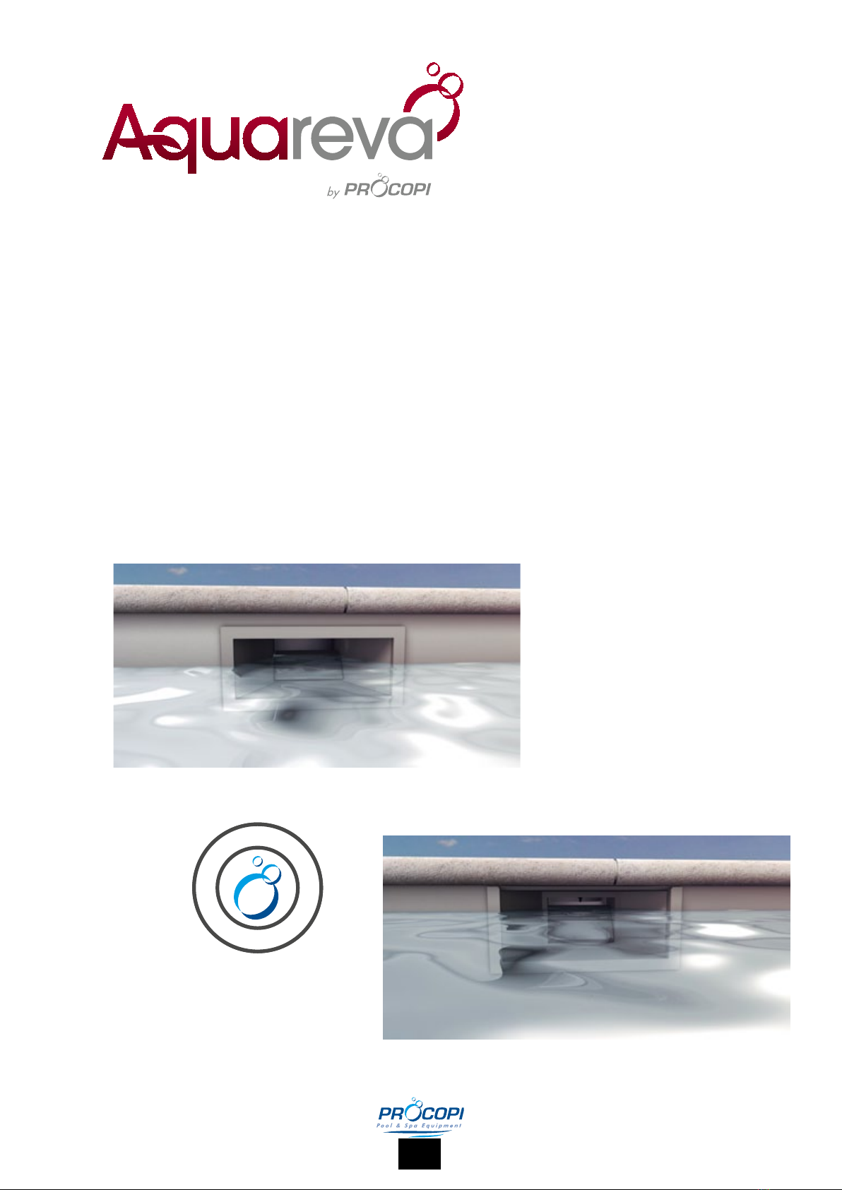
SKIMMER MIRoIR En ABS
ABS MIRRoR SKIMMER
ABS-ÜBERlAufSKIMMER
SKIMMER ESpEjo dE ABS

2014/03 - Indice de révision : A - Code : 0025110
2/32
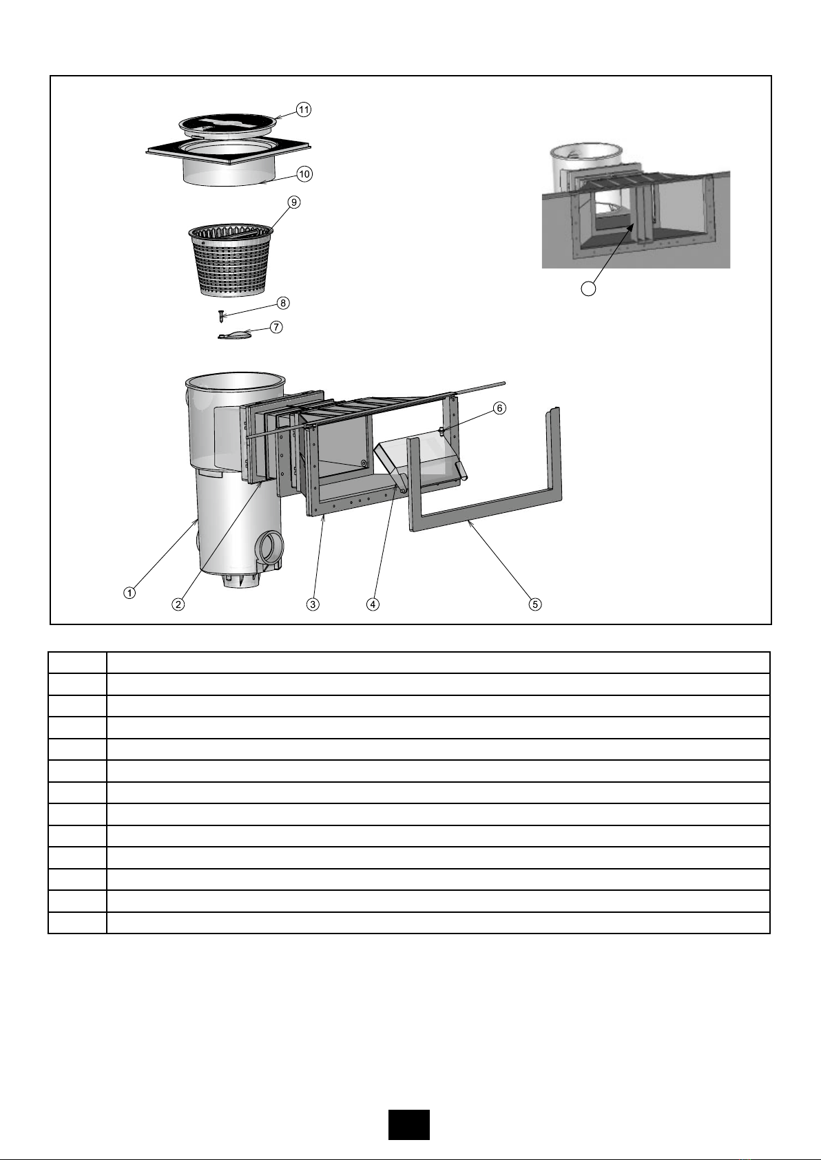
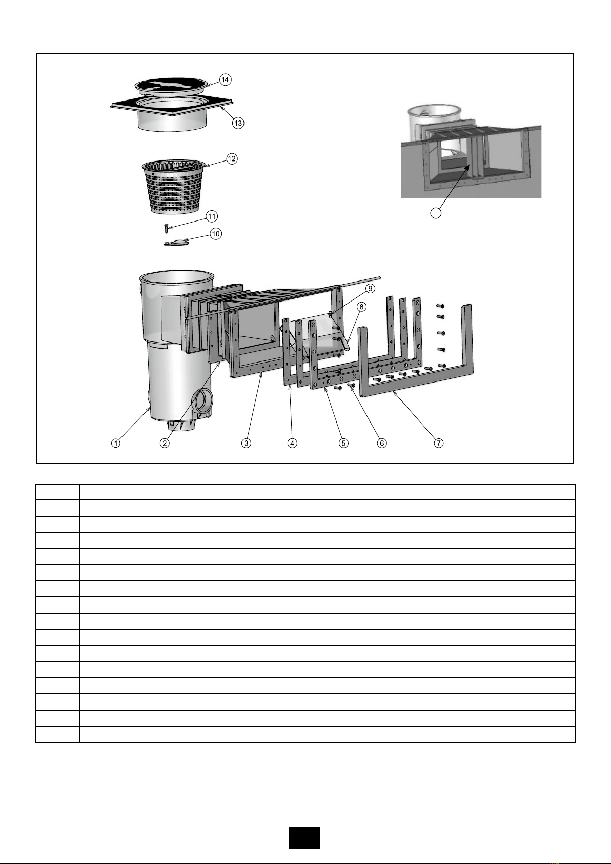
Repère Désignation des composants
1 Corps de skimmer miroir
2 Petite meurtrière (rallonge 145 mm)
3 Grande meurtrière miroir
4 Joint bride grande meurtrière miroir
5 Bride grande meurtrière miroir
6 Vis FZ ST 5,5 x 25 A4
7 Cache bride grande meurtrière miroir
8 Volet de skimmer
9 Butée de volet
10 Obturateur
11 Vis FZ ST 5,5 x 25 A4
12 Panier complet anse droite
13 Cadre à sceller
14 Couvercle
15 Cale de maintien
SL-119-MR
15

2014/03 - Indice de révision : A - Code : 0025110
3/32
Repère Désignation des composants
1 Corps de skimmer miroir béton
2 Petite meurtrière (rallonge 145 mm)
3 Grande meurtrière miroir béton
4 Volet de skimmer
5 Cache bride grande meurtrière miroir béton
6 Butée de volet
7 Obturateur
8 Vis FZ ST 5,5 x 25 A4
9 Panier complet anse droite
10 Cadre à sceller
11 Couvercle
12 Cale de maintien
SB-118-MR
12
2014/03 - Indice de révision : A - Code : 0025110
4/32
FONCTION DU PRODUIT
Permettre un niveau d’eau à 50mm par rapport à l’arase du bassin.
Ecrémage de la surface d’eau du bassin.
Récupération de gros débris (feuilles, jouets, gros insectes...)
Trop plein sécable
Permet l’étanchéité avec le liner (75/100, 85/100, 150/100)
RESTRICTIONS D’USAGE
Margelle piscine
- Longueur mini 500 mm
- Epaisseur mini 30 mm
NOMBRE DE PERSONNES POUR LA POSE ET OUTILLAGE NÉCESSAIRE
Idem skimmer classique. Suivre le DTP n°8 "pièce à sceller" (janvier 1998)
Utiliser exclusivement le mortier fibré et le treillis soudé fournis pour le collage des margelles aux vis-à-vis du skimmer miroir
Prévoir 2 morceaux de Hung à positionner sous les extrémités du renfort inox.
PRÉCONISATION ET CONSIGNE DE SÉCURITÉ
- Le skimmer miroir doit être monté systématiquement avec un système de régulateur de niveau d’eau
automatique et un système de trop plein.
- Le profilé " Hung " doit être impérativement sur 2 cordons de silicone.
- Pour parfaire l'étanchéité le Linerlock doit être impérativement installé.
ENTRETIEN ET MAINTENANCE
Idem pièces à sceller.
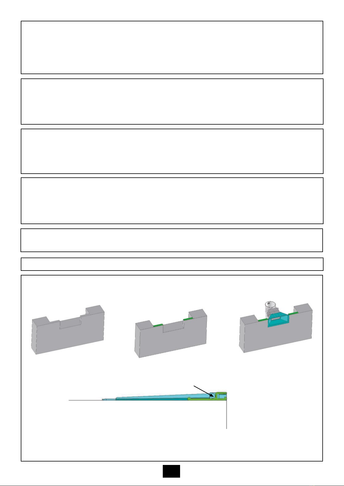
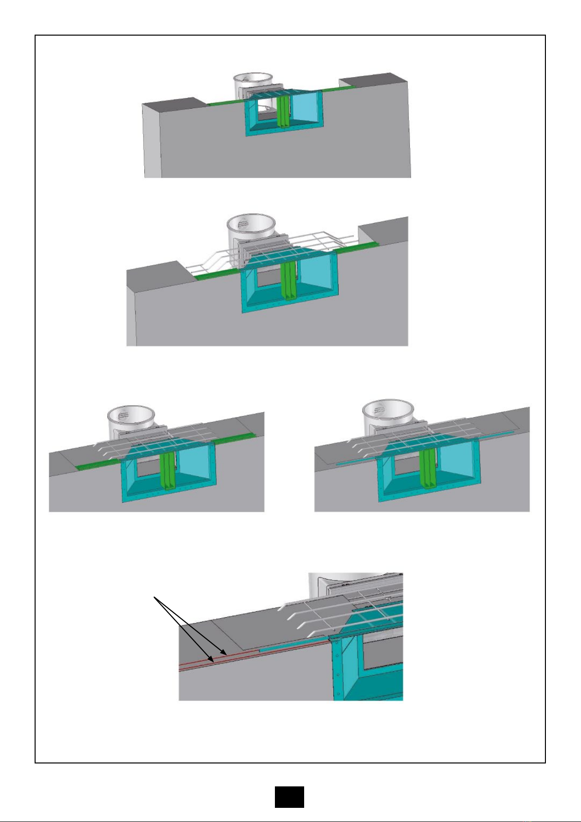
INSTRUCTIONS DE MONTAGE
a. Positionnement de la meurtrière à l’aplomb du mur.
1) Scellement du skimmer
b. Le renfort inox est positionné sur les 2 morceaux de profilé Hung (juste derrière la partie crochet).
c. L’intégralité du dessus de la meurtrière devra être dégraissée avec un chiffon propre légèrement imbibé de
solvant pour raccord PVC puis poncée avec une toile émeri gros grain de sorte de favoriser l’accroche du
mortier fibré sur l’ABS.

2014/03 - Indice de révision : A - Code : 0025110
5/32
d. Placer la cale de maintien au centre de la meurtrière.
e. Positionner le treillis soudé en veillant à ce que ses extrémités soient reprises dans le chaînage du bassin.
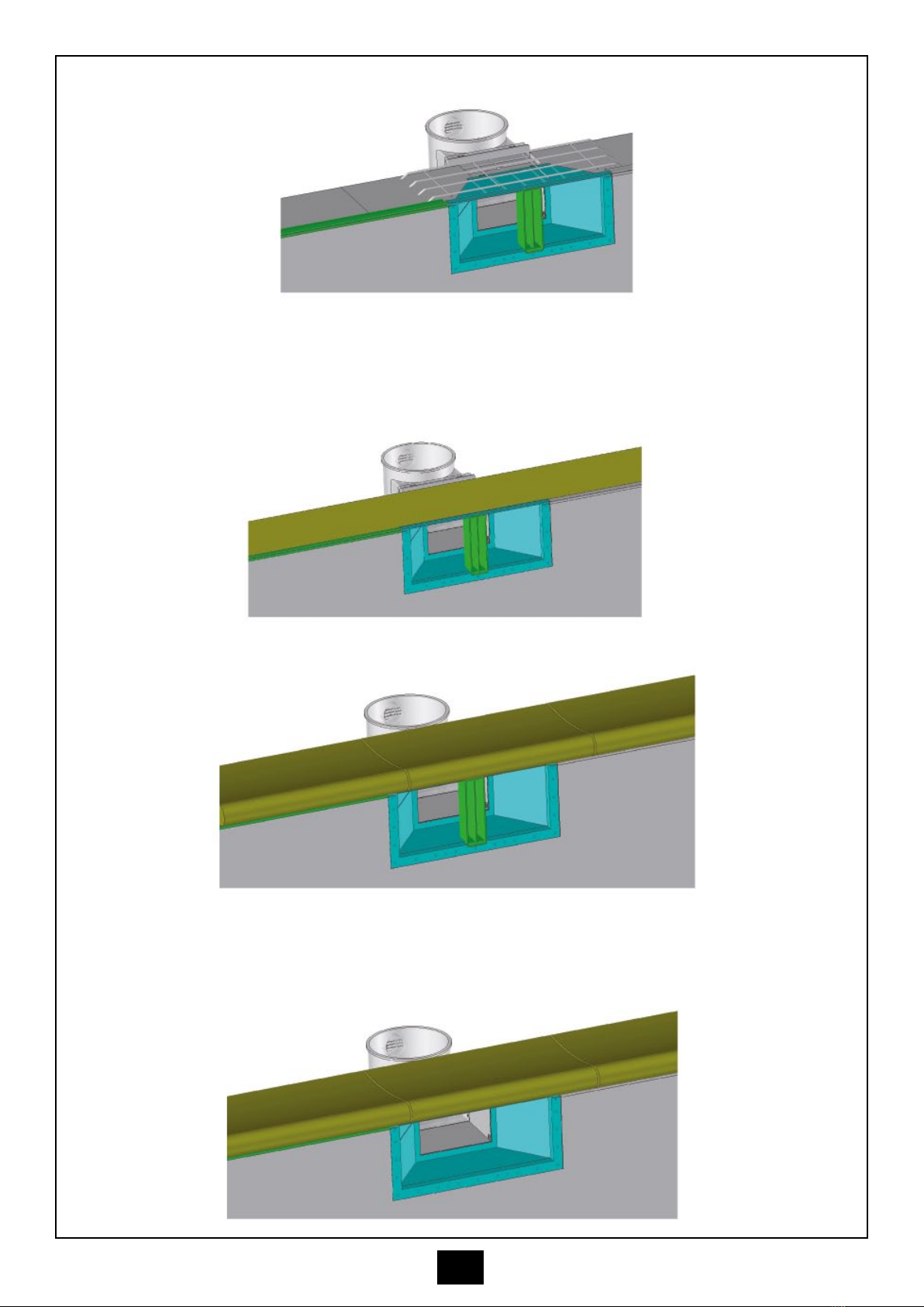
2) Pose du profilé Hung
a. Après séchage du chaînage périphérique retirer les 2 cales de profilé Hung.
b. Enlever les aspérités à l’emplacement du profilé Hung sur la totalité de la périphérie du bassin.
c. Dépoussiérer et réaliser un double joint de silicone avant la pose du profilé Hung. Cette opération est
essentielle pour assurer l’étanchéité entre le profilé Hung et l’arase bassin.
2 joints silicones
2014/03 - Indice de révision : A - Code : 0025110
6/32
d. Fixer le profilé Hung.
3) Scellement des margelles
a. Etaler, sur une surface équivalente à 2 margelles de 500 mm, le mortier fibré pour le collage des
margelles (le treillis doit être intégralement noyé dans le mortier fibré).
b. Poser les margelles.
c. Retirer la cale de maintien de la meurtrière uniquement après séchage complet de l’ensemble.
2014/03 - Indice de révision : A - Code : 0025110
7/32
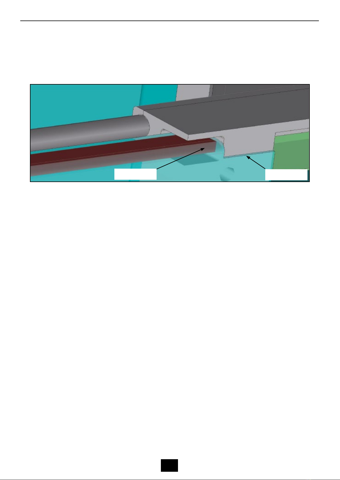
4) Mise en place du liner
a. Positionner le liner et insérer 2 ½ pinces à linge dans les échancrures de la meurtrière.
b. Mettre en eau
c. L’accrochage mâle doit pénétrer à l’intérieur des 2 échancrures. A cet effet, avant de poser la bride, couper la
partie supérieure du liner, uniquement l’accrochage mâle, entre les 2 échancrures. Rabattre les accrochages
mâles dans leurs logements.
d. Poser la bride et son joint.
e. Découper le liner à l’intérieur de la meurtrière.
Découpe Hung Découpe liner
5) Finition
a. Poser le LinerLock en tapotant délicatement, avec un maillet, sur toute la périphérie du bassin. La pose du
LinerLock est essentielle pour assurer l’étanchéité au niveau de l’accrochage.

2014/03 - Indice de révision : A - Code : 0025110
8/32
S.A.S. au capital de 7 000 000 1- R.C.S/Rennes B 333 263 846 000 37

2014/03 - Indice de révision : A - Code : 0025110
9/32
INSTALLATION INSTRUCTIONS AND RECOMMENDATIONS
P
A
T
E
N
T
*
P
R
O
C
O
P
I
SL-119-MR
SB-118-MR
ABS MIRROR SKIMMER

2014/03 - Indice de révision : A - Code : 0025110
10/32
Ref Description
1 Mirror skimmer body, liner
2 Small mouth (extension throat 145 mm)
3 Wide mouth, skimmer, liner
4 Wide mouth flange gasket, mirror skimmer
5 Wide mouth flange, mirror skimmer
6 Screw FZ ST 5.5 x 25 A4
7 Face trim, wide mouth mirror skimmer, liner
8 Skimmer weir
9 Weir stop
10 Shutter
11 Screw FZ ST 5.5 x 25 A4
12 Skimmer basket, straight handle
13 Lid housing
14 Lid
15 Support column
15
SL-119-MR
2014/03 - Indice de révision : A - Code : 0025110
11/32
Ref Description
1 Mirror skimmer body, concrete
2 Small mouth (extension throat 145 mm)
3 Wide mouth, mirror, concrete
4 Skimmer weir
5 Face trim, wide mouth mirror skimmer, concrete
6 Weir stop
7 Shutter
8 Screw FZ ST 5.5 x 25 A4
9 Skimmer basket, straight handle
10 Lid housing
11 Lid
12 Support column
12
SB-118-MR

2014/03 - Indice de révision : A - Code : 0025110
12/32
PURPOSE OF THE PRODUCT
To allow the water level in the pool to be raised to 50 mm from the top of the pool wall.
Skims the surface of the water.
Captures large debris (leaves, toys, large insects, etc.)
Overflow, to be punched out
Leaktight installation with a liner (75/100, 85/100, 150/100)
RESTRICTIONS
Pool coping
- Min length 500 mm
- Min depth 30 mm
TOOLS AND NUMBER OF PEOPLE REQUIRED FOR INSTALLATION
Same as a standard skimmer. According to the DTP n°8 "pool fitting" (January 1998)
Use only the fibrous concrete and welded mesh provided to seal in the copings beside the mirror skimmer
You will need 2 pieces of Hung liner locking track to be placed under the ends of the SS reinforcement.
SAFETY ADVICE AND RECOMMENDATIONS
- The mirror skimmer must be installed with an automatic water level regulator and an overflow system.
- The " Hung " liner locking track must be placed on 2 silicon beads.
- Linerlock must be used to ensure a leaktight seal.
UPKEEP AND MAINTENANCE
As for pool fittings.
ASSEMBLY INSTRUCTIONS
a. Position the mouth flush with the wall
1) Sealing in the skimmer
b. The SS reinforcement is placed on 2 pieces of Hung (just behind the hook section).
c. Clean the entire underside of the skimmer mouth using a rag soaked in a PVC compatible solvant, then sand
it using a rough grain emery paper to improve the adhesion of the fibrous concrete to the ABS surface.
2014/03 - Indice de révision : A - Code : 0025110
13/32
d. Place the support column in the centre of the skimmer mouth
e. Position the welded mesh, making sure that the ends coincides with the pool chaining.
2) Fitting the Hung liner track
a. Once the peripheral chaining is dry, remove the 2 Hung blocks.
b. Smooth out any roughness around the Hung liner locking track around the entire periphery of the pool.
c. Remove any dust and lay down 2 silicon beads before mounting the Hung liner locking track. This is essential
for ensuring leaktightness between the Hung track and the top of the pool wall.
2 silicon beads

2014/03 - Indice de révision : A - Code : 0025110
14/32
d. Mount the Hung liner locking track.
3) Seal in the coping stones
a. Spread a layer of fibrous concrete over an area equivalent to two 500 mm coping stones in order to seal in
the copings (the mesh must be totally encased in the fibrous concrete).
b. Setting the coping stones.
c. Only remove the support column from the skimmer mouth when the concrete is completely set.

2014/03 - Indice de révision : A - Code : 0025110
15/32
4) Fitting the liner
a. FIt the liner and insert 2 half pegs in the recesses in the mouth.
b. Fill the pool with water.
c. The male section should be fitted into both recesses. To ensure this, before mounting the flange, cut the top
part of the liner between the 2 recesses. Push the male section into the recesses.
d. Mount the flange and its seal.
e. Cut the liner inside the skimmer mouth.
Hung cut out Liner cut out
5) Finish
a. insert the LinerLock tapping gently with a hammer around the entire periphery of the pool. The LinerLock must
be used to ensure perfect leaktightness at the point where the liner is fitted into the locking track.

2014/03 - Indice de révision : A - Code : 0025110
16/32
PLC with a share capital of 17,000,000
Register of commerce: Rennes B 333 263 846 000 37
2014/03 - Indice de révision : A - Code : 0025110
17/32
MONTAgEANLEITUNg UND EMpFEhLUNgEN
P
A
T
E
N
T
*
P
R
O
C
O
P
I
SL-119-MR
SB-118-MR
ABS-ÜBERLAUFSKIMMER
2014/03 - Indice de révision : A - Code : 0025110
18/32
Ref Bezeichnung
1 Überlaufskimmer-Gehäuse, Folie
2 Kleine Saugöffnung (Verlängerung 145 mm)
3 Große Saugöffnung, Skimmer, Folie
4 Dichtung, große Saugöffnung, Überlaufskimmer
5 Flansch, große Saugöffnung, Überlaufskimmer
6 Schraube FZ ST 5,5 x 25 A4
7 Blende für Überlaufskimmer, große Saugöffnung, Folie
8 Skimmerklappe
9 Klappenarretierung
10 Geschwindigkeitsregler
11 Schraube FZ ST 5,5 x 25 A4
12 Skimmerkorb mit Griff
13 Deckelrahmen
14 Deckel
15 Stützvorrichtung
15
SL-119-MR

2014/03 - Indice de révision : A - Code : 0025110
19/32
Ref Bezeichnung
1 Überlaufskimmer-Gehäuse, Beton
2 Kleine Saugöffnung (Verlängerung 145 mm)
3 Große Saugöffnung, Skimmer, Beton
4 Skimmerklappe
5 Blende für Überlaufskimmer, große Saugöffnung, Beton
6 Klappenarretierung
7 Geschwindigkeitsregler
8 Schraube FZ ST 5,5 x 25 A4
9 Skimmerkorb mit Griff
10 Deckelrahmen
11 Deckel
12 Stützvorrichtung
12
SB-118-MR

2014/03 - Indice de révision : A - Code : 0025110
20/32
SINN UND ZWECK DES PRODUKTES
Ermöglicht ein Anheben der Wasserlinie auf 50 mm unter Beckenoberkante
Reinigt die Wasseroberfläche
Fängt grobe Verunreinigungen auf (Blätter, Spielzeug, große Insekten etc.).
Überlaufabfluss zum Anschließen nach Bedarf
Leckdichte Installation mit Folienauskleidung (0,8 mm, 0,9 mm, 1,5 mm)
EINSCHRÄNKUNGEN
Jeder Randstein muss
- mindestens 500 mm lang und
- mindestens 30 mm hoch sein.
WERKZEUGE UND ANZAHL DER ZUR MONTAGE ERFORDERLICHEN PERSONEN
Wie bei einem gängigen Skimmer. Gemäß DTP Nr. 8 "Einbauteile" (Januar 1998)
Unter den Randsteinen rechts und links des Skimmers darf nur der mitgelieferte Beton und die Stahlarmierung
verwendet werden.
Die 2 Einhängeleisten werden unter den Edelstahlstäben angebracht.
SICHERHEITSHINWEISE UND -EMPFEHLUNGEN
- Der Überlaufskimmer muss zusammen mit einem automatischen Wasserstandsregler und einem Überlaufsys-
tem installiert werden.
- Das Klemmprofil Hung muss auf 2 Silikonstreifen platziert werden.
- Verwenden Sie einen PVC-Keder, um absolute Leckdichtheit zu erreichen.
INSTANDHALTUNG UND WARTUNG
Wie für Einbauteile.
MONTAGEANLEITUNG
a. Positionieren Sie die Saugöffnung flach an der Wand
1) Einbau des Skimmers
b. Die Edelstahlverstärkung wird auf 2 Längen des Klemmprofils Hung platziert (unmittelbar neben der
Einhängeleiste - Ausschnitt im Skimmer).
c. Reinigen Sie die gesamte Unterseite der Skimmer-Saugöffnung mit einem Lappen, der zuvor in ein für
PVC geeignetes Lösungsmittel getaucht wurde. Schmirgeln Sie sie dann mit einem Schmirgelpapier grober
Körnung ab, damit der Beton besser an der ABS-Oberfläche haften kann.
This manual suits for next models
1
Table of contents
Languages:
Other Procopi Swimming Pool Cleaner manuals


