Prodigit 3260A Series User manual

3260A Series
High Power LOAD
Operation Manual
S/N: 9003260A02 EV:
E

Material Contents Declaration
(材料含量宣称
材料含量宣称材料含量宣称
材料含量宣称)
Hazardous Substance (有毒有害物质或元素)
(Part Name)
零件名称
铅(Pb) 汞(Hg)
镉(Cd)
六价铬
(Cr6+)
多溴联苯
(PBB)
多溴二苯醚
(PBDE)
PCBA
(印刷电路装配件) x ○ x ○ ○ ○
Electrical part not on
PCBA’s
未在PCBA上的电子零件 x ○ x ○ ○ ○
Metal parts
金属零件 ○ ○ ○ x ○ ○
Plastic parts
塑料零件 ○ ○ ○ ○ x x
Wiring
电线 x ○ ○ ○ ○ ○
Package
封装 x ○ ○ ○ ○ ○
对销售之日的所售产品,本表显示, P ODIGIT 供应链的电子信息产品可能包含这些物质。注意:在所售产品中可能会也可
能不会含有所有所列的部件。This table shows where these substances may be found in the supply chain of Prodigit
electronic information products, as of the date of sale of the enclosed product. Note that some of the component types
listed above may or may not be a part of the enclosed product. ○:表示该有毒有害物质在该部件所有均质材料中的含量
均在SJ/T 11363-2006 标准规定的限量要求以下。○:Indicates that the concentration of the hazardous substance in all
homogeneous materials in the parts is below the relevant threshold of the SJ/T 113632006 standard. ×:表示该有毒有害
物质至少在该部件的某一均质材料中的含量超出SJ/T 11363-2006 标准规定的限量要求。×: Indicates that the
concentration of the hazardous substance of at least one of all homogeneous materials in the parts is above the relevant
threshold of the SJ/T 11363-2006 standard.
Note(注释):
1.Prodigit has not fully transitioned to lead-free solder assembly at this moment;However, most of the components
used are oHS compliant.
(此刻,Prodigit 并非完全过渡到无铅焊料组装;但是大部份的元器件一至于RoHS的规定。)
2. The product is labeled with an environment-friendly usage period in years.
The marked period is assumed under the operating environment specified in the product specifications.
(产品标注了环境友好的使用期限制(年)。所标注的环境使用期限假定是在此产品定义的使用环境之下。)
Example of a marking for a 10 year period:
(
例如此标制环境使用期限为10年)

SAFETY SUMMARY
The following general safety precautions must be observed during all phases of operation, service, and
repair of this instrument. Failure to comply with these precautions or with specific warnings elsewhere in this
manual violates safety standards of design, manufacture, and intended use of the instrument. P ODIGIT
assumes no liability for the customer's failure to comply with these requirements.
GENERA
This product is a Safety Class 1 instrument (provided with a protective earth terminal). The protective
features of this product may be impaired if it is used in a manner not specified in the operation instructions.
ENVIRONMENTA CONDITIONS
This instrument is intended for indoor use in an installation category I, pollution degree 2 environments. It is
designed to operate at a maximum relative humidity of 80% and at altitudes of up to 2000 meters. efer to
the specifications tables for the ac mains voltage requirements and ambient operating temperature range.
BEFORE APP YING POWER
Verify that the product is set to match the available line voltage and the correct fuse is installed.
GROUND THE INSTRUMENT
This product is a Safety Class 1 instrument (provided with a protective earth terminal). To minimize shock
hazard, the instrument chassis and cabinet must be connected to an electrical ground. The instrument must
be connected to the ac power supply mains through a three conductor
power cable, with the third wire firmly connected to an electrical ground (safety ground) at the power outlet.
Any interruption of the protective (grounding) conductor or disconnection of the protective earth terminal will
cause a potential shock hazard that could result in personal injury.
FUSES
Only fuses with the required rated current, voltage, and specified type (normal blow, time delay, etc.) should
be used. Do not use repaired
Fuses or short circuited fuse holder. To do so could cause a shock or fire hazard.
DO NOT OPERATE IN AN EXP OSIVE ATMOSPHERE.
Do not operate the instrument in the presence of flammable gases or fumes.
KEEP AWAY FROM IVE CIRCUITS.
Operating personnel must not remove instrument covers. Component replacement and internal adjustments
must be made by qualified service personnel. Do not replace components with power cable connected.
Under certain conditions, dangerous voltages may exist even with the power cable removed. To avoid
injuries, always disconnect power, discharge circuits and remove external voltage sources before touching
components.
DO NOT SERVICE OR ADJUST A ONE.
Do not attempt internal service or adjustment unless another person, capable of rendering first aid and
resuscitation, is present.
DO NOT EXCEED INPUT RATINGS.
This instrument may be equipped with a line filter to reduce electromagnetic interference and must be
connected to a properly grounded receptacle to minimize electric shock hazard. Operation at line voltages or
frequencies in excess of those stated on the data plate may cause leakage currents in excess of 5.0 mA
peak.
DO NOT SUBSTITUTE PARTS OR MODIFY INSTRUMENT.
Because of the danger of introducing additional hazards, do not install substitute parts or perform any
unauthorized modification to the instrument. eturn the instrument to a P ODIGIT ELECT ONICS Sales
and Service Office for service and repair to ensure that safety features are maintained.
Instruments which appear damaged or defective should be made inoperative and secured against
unintended operation until they can be repaired by qualified service personnel.

DEC ARATION OF CONFORMITY
Company Name: P ODIGIT ELECT ONICS CO., LTD
Address: 8/F, No.88, Baojhong d., Sindian City, Taipei County,Taiwan, .O.C.
Declares under sole responsibility that the product as originally delivered
Product Names: DC/AC Electronic Loads
Model Numbers: 326XA、3261XA、3302C、3305C、3300C
(And other customized products based upon the above)
Product Options:
This declaration covers all options and customized products based on the above products.
Complies with the essential requirements of the Low Voltage Directive 73/23/EEC and the EMC Directive
89/336/EEC (including 93/68/EEC) and carries the CE Marking accordingly.
EMC Information:
Class I a sample of the product has been assessed with respect to CE-marking according to the Low Voltage
Directive (73/23/EEC& 93/68/EEC) and EMC Directive (89/336/EEC,92/31/EEC, & 93/68/EEC) and Found
to comply with the essential requirements of the Directives.
The Standard(s) used for showing the compliance and the full details of the results are given in the Test
eports as detailed below:
Safety Information:
Safety standards following:
IEC 61010-1:2010 / EN 61010-1:2010
Feb. 21, 2011
Date
The holder of the verification is authorized to use this verification in connection with the EC declaration Of
conformity according to the Directives. The CE marking may only be used if all releveant and effective EC
Directives are complied with. Together with the manufacturer’s own documented production control, The
manufacturer (or his European authorized representative) can in his EC Declaration of Conformity Verify
compliance with the directives.

3260A Series High Power oad Operation Manual
Table & Contents
CHAPTER 1 INTRODUCTION................................................................................... 1
1-1
General Description...................................................................................... 1
1-2
Characteristics of 3260A Series High Power Electronic Load ...................... 4
1-3
Accessories .................................................................................................. 4
1-4
Option ........................................................................................................... 4
1-5
Specification ................................................................................................. 5
1-6
System Block Diagram ................................................................................. 8
CHAPTER 2 INSTA ATION.................................................................................... 9
2-1
Inspection ..................................................................................................... 9
2-2
Check line voltage ........................................................................................ 9
2-3
Grounding requirements ............................................................................. 10
2-4
Adjust the feet............................................................................................. 10
2-5
ack mount ................................................................................................ 10
2-6
Environmental requirements....................................................................... 10
2-7
epairing .................................................................................................... 10
2-8
GPIB connection......................................................................................... 11
2.9
S-232C Connection.................................................................................. 11
2-10
emote control Port................................................................................... 12
CHAPTER 3 MANUA OPERATION ...................................................................... 13
3-1
Description of Front Panel ........................................................................ 13
3-2
STO E / ECALL operation ...................................................................... 20
3-3
AUTO SEQUENCE testing function description ......................................... 21
3-4
Setting of Freq. & Selection of Bank & Sync............................................... 24
3-5
Initial setting parameter of 3260A Series High Power Electronic Load....... 25
3-6
Consideration of Load Input Connector and Connecting Lead Wire........... 29
3.7
ough Tuning, Fine Tuning & Increment & Decrement Adjustment of Load
Current........................................................................................................ 30
3-8
Imonitor (Output)......................................................................................... 32
3-9
Operation Flow Chart of 3260A Series Electronic Load.............................. 33
3-10
Protection Features ................................................................................... 34
3-11
Load ON voltage adjustment ..................................................................... 36
CHAPTER 4 GPIB/RS-232C OPERATION ............................................................. 37
4-1
Introduction................................................................................................. 37
4-2
The summary of S-232 interface and command ...................................... 37
4-3
3260A Series GPIB/ S-232C COMMAND LIST ........................................ 38
4-4
The description of abbreviation................................................................... 40
4-5
GPIB/ S-232C command description ........................................................ 41
CHAPTER 5 APP ICATION.................................................................................... 56
5-1
CC Operation Mode Application ................................................................. 56
5-2
C Operation Mode Application ................................................................. 57
5-3
LIN Operation Mode Application................................................................. 58
APPENDIX I 3260A R1.00 EDITION WAVE FORM DATA BANK ............................ 1
APPENDIX II SETTING OF AC OR DC E ECTRONIC OAD.................................. 1

Figures
FIG.1-1
ELECTRONIC LOAD POWER CURVE ......................................................................................................1
FIG.1-2 CHARACTERISTICS OF C.C. MODE .........................................................................................................2
FIG.1-3 CHARACTERISTICS OF C.R. MODE .........................................................................................................2
FIG.2-1 SET OF SWITCH.............................................................................................................................................9
FIG.2-2 AC LINE RECEPTACLE..............................................................................................................................10
FIG.2-3 3260A SERIES HIGH POWER ELECTRONIC LOAD FRONT PANEL KEY SWITCH ....................11
FIG.2-4 DIAGRAM OF REMOTE CONTROL PORT ............................................................................................12
FIG.3-1 FRONT PANEL OF 3260A SERIES HIGH POWER ELECTRONIC LOAD ........................................13
FIG.3-2 TYPICAL WAY FOR CONNECTING 3260A SERIES HIGH POWER ELECTRONIC LOAD .........1
FIG.3-3 AUTO SEQ FUNCTION OPERATION FLOW CHART ..........................................................................21
FIG.3-5 TEST MODE OPERATION FLOW-CHART .............................................................................................23
FIG.3-6 DESCRIPTION OF SYNC. ...........................................................................................................................25
FIG 4-1 RS-232 INTERFACE DIAGRAM.................................................................................................................37
Tables
TABLE 1-1 3260A SE IES SPECIFICATION................................................................................7
TABLE 3-1 3260A SE IES HIGH POWE ELECT ONIC LOAD IMONITO SPECIFICATION.19
TABLE 3-2 3260A BUILT-IN WAVE FO M DATA BANK ............................................................24
TABLE 3-3 3260A INITIAL CONDITION SETTING......................................................................26
TABLE 3-4 3261A INITIAL CONDITION SETTING......................................................................26
TABLE 3-5 32611A INITIAL CONDITION SETTING....................................................................26
TABLE 3-6 32612A INITIAL CONDITION SETTING....................................................................27
TABLE 3-7 32613A INITIAL CONDITION SETTING....................................................................27
TABLE 3-8 32614A INITIAL CONDITION SETTING....................................................................27
TABLE 3-9 32615A INITIAL CONDITION SETTING....................................................................28
TABLE 3-10 32616A INITIAL CONDITION SETTING..................................................................28
TABLE 3-11 3260A SE IES OUGH TUNING, FINE TUNING & INC EMENT & DEC EMENT
ADJUSTMENT OF LOAD CU ENT..........................................................................................31
TABLE 3-12 3260A SE IES OVE VOLTAGE P OTECTION SETTING VALUE ......................34
TABLE 3-13 3260A SE IES OVE CU ENT P OTECTION SETTING VALUE......................35
TABLE 3-14 3260A SE IES OVE POWE P OTECTION SETTING VALUE..........................35
TABLE 4-1 GPIB/ S-232C SETTING COMMAND SUMMA Y ...................................................38
TABLE 4-2 GPIB/ S-232C QUE Y COMMAND SUMMA Y......................................................39
TABLE 4-3 GPIB/ S-232C COMMAND TE MINATO ..............................................................40
TABLE 4-4 WAVEFO M INFO MATION ...................................................................................45
P ODIGIT 3260A Series Operation Manual 1
Chapter 1 Introduction
1-1 General Description
3260A Series High Power Electronic Load is used for evaluation of the specification
characteristics of AC/DC high power suppliers and the service life characteristics of batteries.
Especially for step wave-form, square wave-form UPS, inverter device.
3260A Series High Power Electronic Load can be used to work with GPIB/ S-232C interface
and panel manual operation can be made available.
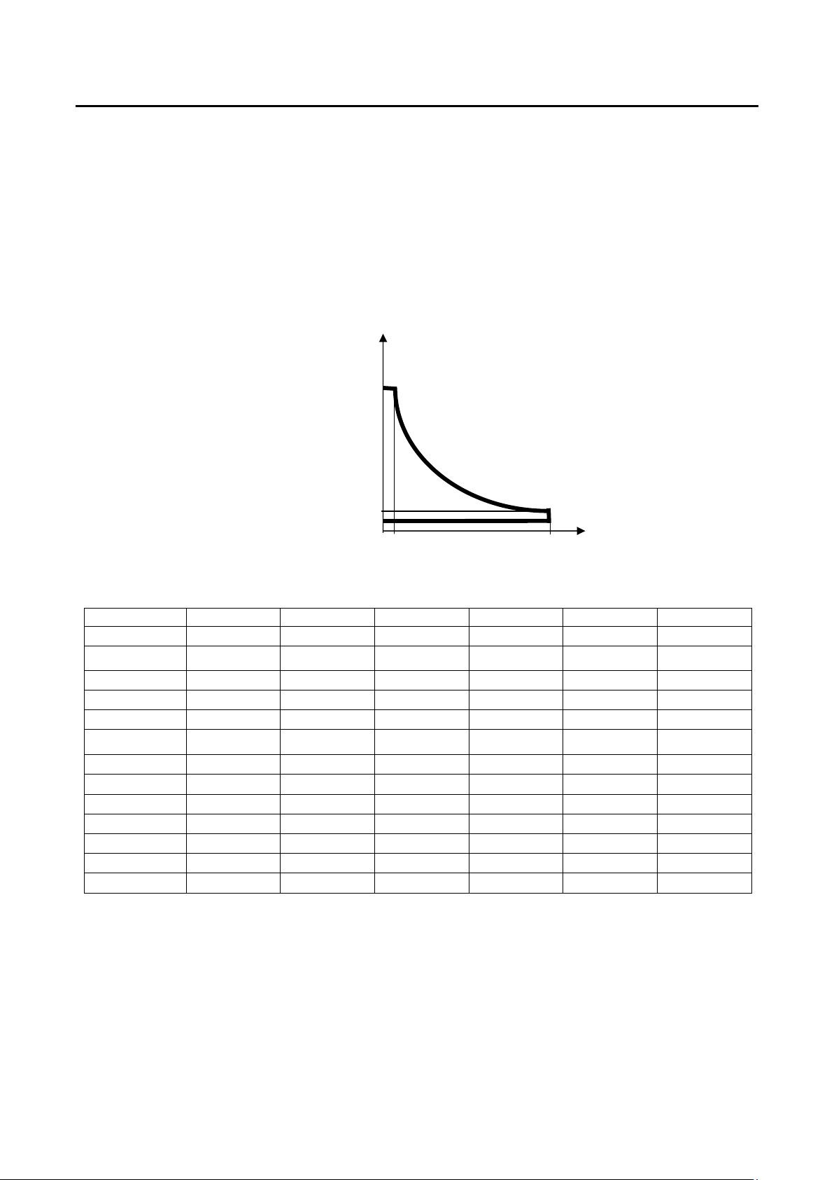
Fig.1-1 Electronic Load Power Curve
Model (A) V (B) V (C) V (D) A (E) A (F) W
3260A 300 V 100 V 50 V 4 A 12 A 1200 W
32601A 300 V 100 V 50 V 8 A 24 A 2400 W
3261A 300 V 100 V 50 V 6 A 18 A 1800 W
32611A 300 V 100 V 50 V 12 A 36 A 3600 W
32612A 300 V 100 V 50 V 18 A 54 A 5400 W
32613A(CC)
300 V 100 V 50 V 24 A 72 A 7200 W
32613A(LIN)
300 V 100 V 60 V 24 A 72 A 7200 W
32614A(CC)
300 V 100 V 50 V 30 A 90 A 9000 W
32614A(LIN)
300 V 100 V 60 V 30 A 90 A 9000 W
32615A(CC)
300 V 100 V 50 V 36 A 108 A 10800 W
32615A(LIN)
300 V 100 V 70 V 36 A 108 A 10800 W
32616A(CC)
300 V 100 V 60 V 42 A 126 A 12600 W
32616A(LIN)
300 V 100 V 75 V 42 A 126 A 12600 W
The work mode of 3260A Series High Power Electronic Load includes C.C, Linear C.C., C. .
C.C. Mode
During C.C. mode, the load current input into 3260A Series High Power Electronic Load
depends on the current setting regardless of the input voltage, e.g., the current setting
remains unchanged. Please refer to Fig.1-9 below:
(F) W CONTOU
(A)
(E)
(B)
(D)
(C)
V
I

2 P ODIGIT
I
V
CC
LOAD
CU ENT
CU ENT SETTING
INPUT VOLTAGE
Fig.1-2 Characteristics of C.C. Mode
inear C.C. Mode
During Linear C.C. mode, the load current input into 3260A Series High Power Electronic
Load depends on the current setting regardless of the input voltage, e.g., the current setting
remains unchanged. Please refer to Fig.1-9. The load input current signal will follow input
voltage signal, That is useful for step wave-form and square wave-form device.
The LIN mode is within a AGC circuit and the control signal will response with input voltage.
We call it LIN mode.
The AGC circuit produces a constant amplitude output signal so long as the amplitude of the
input signal exceeds an adjustable reference voltage applied to the peak detector. The
reference voltage may be changed to change the range of input voltage resulting in a
constant-amplitude output.
The AGC circuit responds almost instantly to control a sudden increase in input voltage.
The AGC circuit is especially suitable for Step waveform, Square waveform and the input
voltage with distortion waveform.
C.R. Mode
During C. . mode, the load current input into 3260A Series High Power Electronic Load
depends on the resistance setting. At this time, the load current is in direct proportion to input
voltage, e.g. the resistance setting remains unchanged. Please refer to Fig. 1.10 below
I
V
LOAD
CU ENT
INPUT VOLTAGE
ESISTANCE
SETTING
Fig.1-3 Characteristics of C. . Mode

P ODIGIT 3260A Series Operation Manual 3
The load setting of 3260A Series High Power Electronic Load and the load condition setting
of the front panel can be made through the front panel manual operation, GPIB command.
The load voltage and current can be transmitted to the computer through GPIB bus. For
operation of GPIB, please refer to chapter 4 GPIB Operation.

4 P ODIGIT
1-2 Characteristics of 3260A Series High Power Electronic oad
1.2.1 Interface function of full GPIB control, including setting of load condition and read-
back of Vmeter and Ameter.
1.2.2 Dual High Accuracy/High esolution 4 1/2 digit Vmeter and Ameter.
1.2.3 In CC mode, frequency range for DC , 0.1~400 Hz.
1.2.4 In CC mode, the settable Crest Factor can be set to Maximum 3.5.
1.2.5 Automatic judging ability for GO/NG.
1.2.6 Switch-able automatic voltage sensing ability.
1.2.7 Protection functions include Over - Voltage, Over - Current, Over - Power and Over -
Temperature.
1.2.8 Software calibration ability.
1.2.9 Cooling fan control device with revolution change function.
1.2.10 Isolated Current Monitor BNC output with full scale of 10V.
1-3 Accessories
1.3.1 Vsense Input BNC Connector 1 PC
1.3.2 Banana Terminal (Black) 1 PC
1.3.3 Banana Terminal ( ed) 1 PC
1.3.4 King-Size Hook-Type Terminal 2 PC
1.3.5 3260A Series High Power AC/DC Electronic Load Operation Manual 1 PC
1-4 Option
1.4.1 GPIB cable 1 M
1.4.2 GPIB cable 2 M
1.4.3 9931 emote Controller 1 Set
1.4.4 D-SUB 9 Pin to D-SUB 9 Pin cable 1 M

P ODIGIT 3260A Series Operation Manual 5
1-5 Specification
MODEL 3261A 32611A 32612A 32613A 32614A 32615A
LOAD INPUT ATINGS
Power (VA)
Current(Ampere)
Voltage(Volt)
1800 VA
18 Arms
50~300 Vrms
3600 VA
36 Arms
50~300 Vrms
5400 VA
54 Arms
50~300 Vrms
7200 VA
72 Arms
50~300 Vrms
9000 VA
90 Arms
50~300 Vrms
10800 VA
108 Arms
50~300 Vrms
P OTECTION:
Over Power Protection
Over Current Protection
Over Voltage Protection
Over Temp. Protection
≒ 1890 VA
≒ 18.9 A
≒ 315 V
85℃
≒ 3780 VA
≒ 37.8 A
≒ 315 V
85℃
≒ 5670 VA
≒ 56.7 A
≒ 315 V
85℃
≒ 7560 VA
≒ 75.6 A
≒ 315 V
85℃
≒ 9450 VA
≒ 94.5 A
≒ 315 V
85℃
≒ 11340 VA
≒ 113.4 A
≒ 315 V
85℃
ange 0~9/9~18
A
0~18/18~36
A
0~27/27~54
A
0~36/36~72
A
0~45/45~90
A
0~54/54~108
A
esolution
2.25/4.5 mA
4.5/9 mA 6.75/13.5 mA
9/18 mA
11.25/21.5 mA
13.5/27 mA
Accuracy ±( 0.5﹪ of setting + 1﹪ of range );
±0.5﹪ of (setting + range)@ 50/60Hz
0~0.9 A 0~1.8 A 0~2.7 A 0~3.6 A 0~4.5 A 0~5.4 A
CC MODE
&
Linear CC
MODE Low
Current
Accuracy ± 2 % of (setting + range)
ange II/I 3.333~13.33
2~53.332K
1.667~6.668
~26.668K
1.111~4.444
~17.776K
0.833~3.333
~13.33K
0.666~2.666
~10.666K
0.556~2.224
~8.888K
esolution
0.019/0.076
mS
0.037/0.148
mS
0.056/0.224
mS
0.075/0.300
mS
0.0937/0.375
mS
0.113/0.452
mS
Accuracy ( 0.5﹪ of setting + 2﹪ of range );
±0.5﹪ of (setting + range)@ 50/60Hz
C MODE
Under 5 ﹪
F.S.Current
±2﹪ of (setting + range)
ange √2 ~ 3.5 / 1.5 ~ 1.9 / 3.0 ~ 3.4
C EST
FACTO
(CCMODE
ONLY) esolution
0.5 / 0.1 / 0.1
VOLTAGE ange 300 V 300 V 300 V 300 V 300 V 300 V
EADBACK
esolution
0.1 V 0.1 V 0.1 V 0.1 V 0.1 V 0.1 V
V METE Accuracy ±( 0.5﹪ of reading + 0.2﹪of range )
DVM under 1% don’t display.
CU ENT ange 18 A 36 A 54 A 72 A 90 A 108 A
EADBACK
esolution
0.001 A 0.01 A 0.012 A 0.012 A 0.01 A 0.012 A
A METE Accuracy ±( 0.5﹪ of reading + 2﹪ of range );
±0.5﹪ of (reading + range)@ 50/60Hz
WATT ange 1800 W 3600 W 5400 W 7200 W 9000W 10800 W
EADBACK
esolution
0.1 W 1 W 1.2 W 1.2 W 1W 1.2 W
Accuracy ±( 0.5﹪ of reading + 2﹪ of range );
±0.5﹪ of (reading + range)@ 50/60Hz
W METE Under 5 ﹪
F.S.Current
±3﹪ of (setting + range)
VA METE Vrms×Arms Correspond To Vrms and Arms
F EQUENCY ange DC , 40~400 Hz(CC Mode) ; DC , 0.1~400 Hz(LIN,C Mode)
Imonitor (Isolated) 4.5 A/V 9 A/V 13.5 A/V 18 A/V 22.5A/V 27 A/V

6 P ODIGIT
MODEL 3260A 32601A 32616A
LOAD INPUT ATINGS
Power (VA)
Current(Ampere)
Voltage(Volt)
1200 VA
12 Arms
50~300 Vrms
2400 VA
24 Arms
50~300 Vrms
12600VA
126Arms
60~300Vrms
P OTECTION:
Over Power Protection
Over Current Protection
Over Voltage Protection
Over Temp. Protection
≒ 1260 VA
≒ 12.6 A
≒ 315 V
85℃
≒ 2520 VA
≒ 25.2 A
≒ 315 V
85℃
≒ 13230 VA
≒ 132.3 A
≒ 315 V
85℃
ange 0~6/6~12 A 0~12/12~24 A
0 ~ 63/126 A
esolution 1.5/3 mA 3/6 mA 15.75/31.5mA
Accuracy
±( 0.5﹪ of setting + 1﹪ of range );
±0.5﹪ of (setting + range)@ 50/60Hz
0~0.6 A 0~1.2 A 0 ~ 6.3 A
CC MODE
&
Linear CC
MODE Low
Current
Accuracy
± 2 % of (setting + range)
ange II/I 5~20~
80K
2.5~10~
40K
0.476~1.904~
7.616K
esolution 0.013 /
0.052 mS
0.025 /
0.1 mS
0.5252S /
0.1313mS
Accuracy ±( 0.5﹪ of setting + 2﹪ of range );
±0.5﹪ of (setting + range)@ 50/60Hz
C MODE
Under 5 ﹪
F.S.Current
±2﹪ of (setting + range)
ange
√2 ~ 3.5 / 1.5 ~ 1.9 / 3.0 ~ 3.4
C EST
FACTO
(CCMODE
ONLY) esolution 0.5 / 0.1 / 0.1
VOLTAGE ange 300 V 300 V 300 V
EADBACK esolution 0.1 V 0.1 V 0.1 V
V METE Accuracy ±( 0.5﹪ of reading + 0.2﹪of range )
DVM under 1% don’t display.
CU ENT ange 12 A 24 A 126 A
EADBACK esolution 0.001 A 0.01 A 0.014 A
A METE Accuracy
±( 0.5﹪ of reading + 2﹪ of range );
±0.5﹪ of (reading + range)@ 50/60Hz
WATT ange 1200 W 2400 W 12600 W
EADBACK esolution 0.1 W 0.1 W 1 W
Accuracy
±( 0.5﹪ of reading + 2﹪ of range );
±0.5﹪ of (reading + range)@ 50/60Hz
W METE Under 5 ﹪
F.S.Current
±3﹪ of (setting + range)
VA METE Vrms×Arms Correspond To Vrms and Arms
F EQUENCY ange DC , 40~400 Hz(CC Mode) ;
DC , 0.1~400 Hz(LIN,C Mode)
Imonitor (Isolated) 3 A/V 6 A/V 31.5A/V

P ODIGIT 3260A Series Operation Manual 7
LINE 100V/115V±10﹪
200V/230V±10﹪
F EQUENCY 50/60 HZ
AC INPUT
FUSE 2A/250V (5*20mm)
1A/250V (5*20mm)
MAX. POWE CONSUMPTION
100 W
DIMENSIONS (W*H*D) 440 mm*177 mm*445 mm / EA
EACH UNIT
WEIGHT NET : 23.6 Kg / EA
Table 1-1 3260A Series Specification
8 P ODIGIT
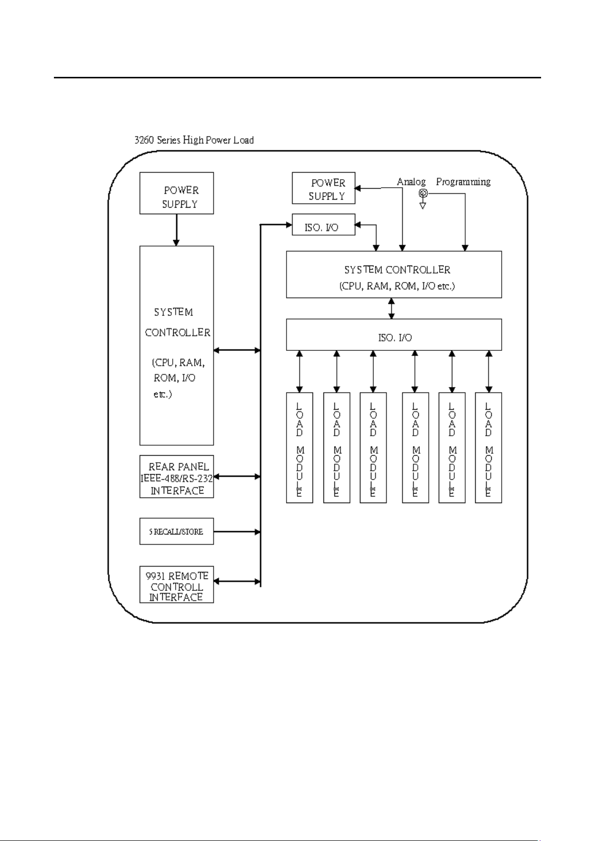
1-6 System Block Diagram
P ODIGIT 3260A Series Operation Manual 9
Chapter 2 Installation
2-1 Inspection
The 3260A Series High Power Electronic Load was carefully inspected before shipment. If
instrument damage has occurred during transport, please inform Prodigit's sales and service
office or representative.
Your 3260A Series High Power Electronic Load was shipped with a power cord for the type
of outlet used at your location. If the appropriated cord was not included, please contact your
nearest Prodigit sales office to obtain the correct cord. efer to " check line voltage " to check
the line voltage selection and fuse type.
2-2 Check line voltage
The 3260A Series High Power Electronic Load can operation with 115, 230Vac input as
indicated on the label on the rear panel.
Make sure that the factory check mark correspond to your nominal line voltage. Skip this
procedure if the label is corrected marked.
2.2.1 With the 3260A Series High Power Electronic Load power OFF, disconnect the
power cord.
2.2.2 efer the drawing on the rear panel in Fig 2-1, set the switches to the proper voltage
as describe in the following:
1
1
5
RANGE
SYNC INPUT
Fig.2-1 SET OF SWITCH
2.2.3 Mark the correct voltage on the rear panel of 3260A Series High Power Electronic
Load.
2.2.4 Check the rating of the line fuse and replace it with the correct fuse if necessary.
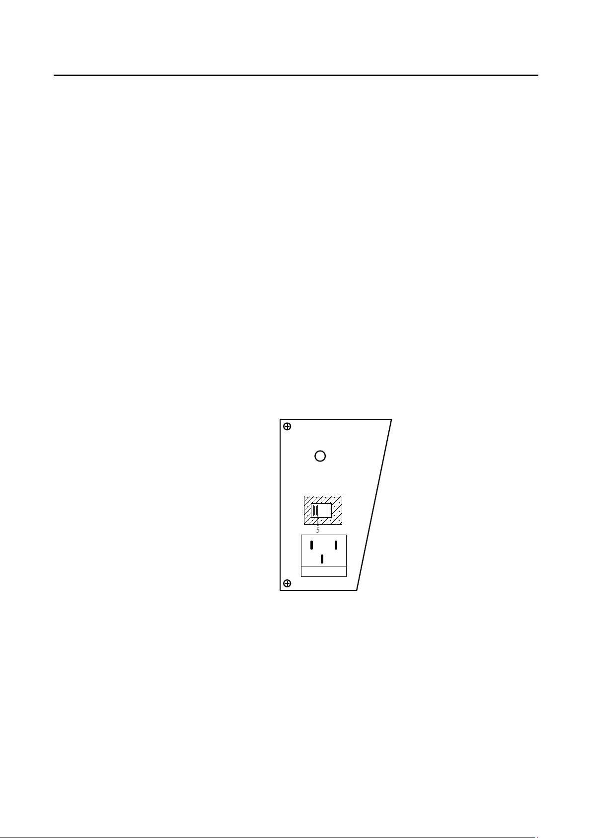
2.2.5 The line fuse is located below the AC line receptacle see Fig 2-2. With the power
cord removed, use a small screwdriver to extract the fuse holder from under the AC
socket. eplace the fuse with the appropriate type as indicated in Table 1-1. These
fuses are normal-blow fuses.

10 P ODIGIT
2.2.6 einstall fuse holder and connect the power cord.
Fig.2-2 AC LINE ECEPTACLE
2-3 Grounding requirements
The 3260A Series High Power Electronic Load is equipped with three conductor cable which
plugs in an appropriate receptacle to ground the instrument's cover.
2-4 Adjust the feet
The 3260A Series High Power Electronic Load is equipped with feet and tilt stands installed
and is ready for used as a bench instrument.
The feet provide a good viewing angle for bench-top use.
2-5 Rack mount
The 3260A Series High Power Electronic Load is designed to permit mounted in a standard
19 inches rack for system application.
2-6 Environmental requirements
The operating temperature should keep between 0 degree and 40 degree, while the ideal
operating temperature is 25 ± 5 degree.
2-7 Repairing
If the instrument is damaged, please attach a tag to the instrument to identify the owner and
indicated the require service or repairing. And inform the Prodigit sales and service office or
representative.

P ODIGIT 3260A Series Operation Manual 11
2-8 GPIB connection
The GPIB connector on the rear panel connects the 3260A Series High Power Electronic
Load mainframe to the controller and to other GPIB devices. An GPIB system can be
connected in any configuration (star, linear, or both) as long as
2.8.1 The maximum number of devices including the controller is no more than 15.
2.8.2 The maximum length of all cable in no more than 2 meters times the number of
devices connected together, up to 20 meters maximum.
Please make sure the lock screws are firmly hand - tightened, use a screw-driver
only for the removal of screws. Fig 2-3 shows the rear panel of 3260A Series High
Power Electronic Load mainframe, the GPIB connector is located on the rear panel of
3260A Series High Power Electronic Load mainframe. The GPIB address of the
3260A Series High Power Electronic Load mainframe is set on front panel.
2.8.3 GPIB address setting:
GPIB address is set by press STATE 4 + STATE 5 simultaneously, press UP or
DOWN key to select 0-31 address number, press STATE 2 to exit GPIB address
setting mode.
Fig.2-3 3260A Series High Power Electronic Load front panel key switch
2.9 RS-232C Connection
The S-232C connector (Female) on the rear panel connects 3260A Series High Power
Electronic Load mainframe to S-232C port of computer in one by one configuration.

12 P ODIGIT
2-10 Remote control Port
The D-sub 9 pin connector on the rear panel connects the 3260A Series High Power
Electronic Load to the P ODIGIT mode 9931 remote controller and to replace the ECALL
option key 1 to 5 on the front panel of 3260A Series High Power Electronic Load.
1
2
3
4
5
STO E
1
2
3
4
5
6
7
8
9
NC
NC
NC
NC
D-sub 9 Pin
INSTRUMENT PROFESSIONAL
PRODIGIT
PRODIGITPRODIGIT
PRODIGIT
9931
1
REMOTE INTERFACE
2
3
4
5
9 Pin to 9 Pin 1.5M Cable
Fig.2-4 Diagram of emote Control Port

P ODIGIT 3260A Series Operation Manual 13
Chapter 3 Manual Operation
This Chapter deals with the front panel manual operation of 3260A Series High Power Electronic
Load. With regard to calibration procedures, please refer to 3260A Series High Power Load
Calibration Manual. With regard to the control of GPIB/ S-232C control, please refer to Chapter 4
GPIB/ S-232C emote Operation.
3-1 Description of Front Panel
Fig.3-1 Front Panel of 3260A Series High Power Electronic Load

14 P ODIGIT
3.1.1 3260A 300V/12A, 1200W AC/DC Electronic Load
efers to model number, voltage, current and power specification of 3260A Series
High Power AC/DC Electronic Load.
3.1.2 NG LED Indicator
When the reading of Vmeter, Ameter, wattmeter or VA meter exceeds the upper or
lower limit set, this indicator will display.
3.1.3 MODE Key and LED indicator of CC, LIN, C
On the 3260A Series High Power Electronic Load, there are two working modes
which can be selected by MODE KEY with the sequence of C.C., Linear C.C. and
C. ., then switching can be made in such a sequence. However, LED indicator of CC,
LIN, C will display the working mode selected.
3.1.4 EM LED Indicator
When 3260A Series High Power Electronic Load is connected with computer
program for control and operation, EM LED Indicator will come on. In such a case,
panel manual operation will become null and void. When EM LED indicator comes
off, panel manual operation will resume.
3.1.5 Upper 4-1/2 Digit Monitor
This 4-1/2 Digit Monitor is a multi-function monitor. Its functions are described as
follows:
3.1.5.1 Under general conditions:
This monitor will be a 4-1/2 digit voltmeter to display the voltage at the load
input end or Vsense BNC input end.
3.1.5.2 Under WATT ON condition:
This monitor will be a 4-1/2 digit wattmeter to display the power of the load.
3.1.5.3 Under LIMIT ON condition:
This monitor will display the upper limit of the voltmeter, Ameter, wattmeter
and VA meter. Its displaying sequence is as follows:
3.1.5.3.1 Display the upper limit of voltmeter with the unit as〝Vrms〞.
3.1.5.3.2 Display the upper limit of ammeter with the unit as〝Arms〞.
3.1.5.3.3 Display the upper limit of wattmeter with the unit as〝W〞.
3.1.5.3.4 Display the upper limit of VA meter with the unit as〝VA〞.
3.1.5.4 Upon protection conditions:
For over-voltage protection, monitor displays〝oVP〞.
3.1.5.5 Under F EQ ON condition:
The monitor will display EfEq, bAn, Sync function settings, its displaying
sequence is as follows:
3.1.5.5.1 Under frequency setting function, monitor displays〝FrEq〞.
3.1.5.5.2 Under Bank selection function, monitor displays〝bAn〞.
3.1.5.5.3 Under SYNC selection function, monitor displays〝Sync〞.
This manual suits for next models
9
Table of contents
Other Prodigit Power Supply manuals


Popular Power Supply manuals by other brands


Allanson
Allanson 2270 Series instruction manual

Horizont
Horizont ranger AN3000 instruction manual

iseg
iseg EHQ F007n-F Operator's manual

Altronix
Altronix SMP5E Installation instructions manual

National Instruments
National Instruments PS-16 user manual

TDK-Lambda
TDK-Lambda GH10-150 Product Safety & Installation Manual


