Prodigit 3350F Series User manual

3350F Series
High power
Electronic Load
Operation manual
S/N:9003350F04 REV: I

SAFETY SYMBOLS
Direct current (DC)
Alternating current (AC)
Both direct and alternating
Three
-
phase altern
ating
Off (Supply)
On (Supply)
Protective earth
Caution
!
Refer to this anual before using the eter.
Caution, risk of electric shock
CAT IV – Is for measurements performed at the source of the low-voltage
installation.
CAT III – Is for measurements performed in the building installation.
CAT II – Is for measurements performed on circuits directly connected to the
low-voltage installation.
CAT I – Is for measurements performed on circuits not directly connected to
Fuse

Material Contents Declaration
(材料含量宣称)
Hazardo s S bstance (有毒有害物质或元素)
(Part Name)
零件名称 铅
(Pb)
汞
(Hg)
镉
(Cd)
六价铬
(Cr6+)
多溴
联苯
(PBB)
多溴
二苯醚
(PBDE)
PCBA
(印刷电路装配件) X O X O O O
Electrical part not on PCBA’s
未在PCBA上的电子零件 X O X O O O
Metal parts
金属零件 O O O X O O
Plastic parts
塑料零件 O O O O X X
Wiring
电线 X O O O O O
Package
封装 X O O O O O
对销售之日的所售产品,本表显示, PRODIGIT 供应链的电子信息产品可能包含这些物质。注意:所售产品中可能
会也可能不会含有所有所列的部件。This table shows where these substances may be found in the supply chain
of Prodigit electronic information products, as of the date of sale of the enclosed product. ote that some of the
component types listed above may or may not be a part of the enclosed product. ○:表示该有毒有害物质 该部
件所有均质材料中的含量均 SJ/T 11363-2006 标准规定的限量要求以下。○:Indicates that the concentration of
the hazardous substance in all homogeneous materials in the parts is below the relevant threshold of the SJ/T
113632006 standard. ×:表示该有毒有害物质至少 该部件的某一均质材料中的含量超出SJ/T 11363-2006 标准
规定的限量要求。×: Indicates that the concentration of the hazardous substance of at least one of all
homogeneous materials in the parts is above the relevant threshold of the SJ/T 11363-2006 standard.
ote(注释):
1.Prodigit has not fully transitioned to lead-free solder assembly at this moment;However, most of the
components used are RoHS compliant.
(此刻,Prodigit 并非完全过渡到无铅焊料组装;但是大部份的元器件一至于RoHS的规定。)
2. The product is labeled with an environment-friendly usage period in years.
The marked period is assumed under the operating environment specified in the product specifications.
(产品标注了环境友好的使用期限制(年)。所标注的环境使用期限假定是在此产品定义的使用环境之下。)
Example of a marking for a 10 year period:
(例如此标制环境使用期限为10年)

SAFETY SUMMARY
The following general safety precautions must be observed during all phases of operation, service,
and repair of this instrument. Failure to comply with these precautions or with specific warnings
elsewhere in this manual violates safety standards of design, manufacture, and intended use of
the instrument. PRODIGIT assumes no liability for the customer's failure to comply with these
requirements.
GENERAL
This product is a Safety Class 1 instrument (provided with a protective earth terminal). The
protective features of this product may be impaired if it is used in a manner not specified in the
operation instructions.
ENVIRONMENTAL CONDITIONS
This instrument is intended for indoor use in an installation category I, pollution degree
environments. It is designed to operate at a maximum relative humidity of 80% and at altitudes of
up to 000 meters. Refer to the specifications tables for the ac mains voltage requirements and
ambient operating temperature range.
BEFORE APPLYING POWER
Verify that the product is set to match the available line voltage and the correct fuse is installed.
GROUND THE INSTRUMENT
This product is a Safety Class 1 instrument (provided with a protective earth terminal). To
minimize shock hazard, the instrument chassis and cabinet must be connected to an electrical
ground. The instrument must be connected to the ac power supply mains through a three
conductor
power cable, with the third wire firmly connected to an electrical ground (safety ground) at the
power outlet. Any interruption of the protective (grounding) conductor or disconnection of the
protective earth terminal will cause a potential shock hazard that could result in personal injury.
FUSES
Only fuses with the required rated current, voltage, and specified type (normal blow, time delay,
etc.) should be used. Do not use repaired
Fuses or short circuited fuse holder. To do so could cause a shock or fire hazard.
DO NOT OPERATE IN AN EXPLOSIVE ATMOSPHERE.
Do not operate the instrument in the presence of flammable gases or fumes.
KEEP AWAY FROM LIVE CIRCUITS.
Operating personnel must not remove instrument covers. Component replacement and internal
adjustments must be made by qualified service personnel. Do not replace components with power
cable connected. Under certain conditions, dangerous voltages may exist even with the power
cable removed. To avoid injuries, always disconnect power, discharge circuits and remove
external voltage sources before touching components.
DO NOT SERVICE OR ADJUST ALONE.
Do not attempt internal service or adjustment unless another person, capable of rendering first aid
and resuscitation, is present.
DO NOT EXCEED INPUT RATINGS.
This instrument may be equipped with a line filter to reduce electromagnetic interference and must
be connected to a properly grounded receptacle to minimize electric shock hazard. Operation at
line voltages or frequencies in excess of those stated on the data plate may cause leakage
currents in excess of 5.0 mA peak.
DO NOT SUBSTITUTE PARTS OR MODIFY INSTRUMENT.
Because of the danger of introducing additional hazards, do not install substitute parts or perform
any unauthorized modification to the instrument. Return the instrument to a PRODIGIT
ELECTRONICS Sales and Service Office for service and repair to ensure that safety features are
maintained.
Instruments which appear damaged or defective should be made inoperative and secured against
unintended operation until they can be repaired by qualified service personnel.

DECLARATION OF CONFORMITY
Co pany Na e: PRODIGIT ELECTRONICS CO., LTD
Address: 8F, No.88, Baojhong Rd., Sindian City, Taipei County,Taiwan, R.O.C.
Declares under sole responsibility that the product as originally delivered
Product Na es: DC Electronic Loads
Model Nu bers: 3350F、3351F、335 F、3353F、3354F、3356F
(And other customized products based upon the above)
Safety and EMC Infor ation:
This declaration covers all options and customized products based on the above products.
Complies with the essential requirements of the Low Voltage Directive 006/95/EC and the EMC
Directive 004/108/EC and carries the CE Marking accordingly.
Safety standard:
Safety standards following:
IEC 61010-1: 010 / EN 61010-1: 010
EMC standard:
EN 613 6-1: 006
EN 613 6- -1: 006
EN 55011: 009+A1: 010
EN 61000-3- : 006+A1: 009+A : 009
EN 61000-3-3: 008
EN 61000-4- : 009
EN 61000-4-3: 006+A1: 008+A : 010
EN 61000-4-4: 004+A1: 010
EN 61000-4-5: 006
EN 61000-4-6: 009
EN 61000-4-8: 010
EN 61000-4-11: 004
Oct 7, 01
Date
Larsson Tsou / R&D Assistant Manager
The holder of the verification is authorized to use this verification in connection with the EC
declaration Of conformity according to the Directives. The CE marking may only be used if all
releveant and effective EC Directives are complied with. Together with the manufacturer’s own
documented production control, The manufacturer (or his European authorized representative)
can in his EC Declaration of Conformity Verify compliance with the directives.

3350F Series High Power Electronic load operation manual
Table of Contents
CHAPTER 1 INTRODUCTION........................................................................................................................... 1
1-1. GENERAL DESCRIPTION ......................................................................................................................... 1
1-2. FEATURES ........................................................................................................................................... 9
1-3. ACCESSORIES ...................................................................................................................................... 9
1-4. OPTION ............................................................................................................................................... 9
1-5. SPECIFICATIONS ................................................................................................................................... 9
CHAPTER 2 INSTALLATION.......................................................................................................................... 12
2-1. INSPECTION ....................................................................................................................................... 12
2-2. CHECK LINE VOLTAGE ......................................................................................................................... 12
2-3. FUSE EXCHANGE ................................................................................................................................ 13
2-4. GROUNDING REQUIREMENTS................................................................................................................ 14
2-5. ADJUST THE FEET ............................................................................................................................... 14
2-6. RACK MOUNT ..................................................................................................................................... 14
2-7. ENVIRONMENTAL REQUIREMENTS ......................................................................................................... 14
2-8. OBSERVE THE INTERNATIONAL ELECTRICAL SYMBOL LISTED BELOW......................................................... 14
2-9. CLEANING .......................................................................................................................................... 15
2-10. POWER UP........................................................................................................................................ 15
2-11. CONNECTION TO THE LOAD INPUT TERMINAL ON THE REAR PANEL ........................................................... 15
2-12. REPAIR.............................................................................................................................................. 15
2-13. GPIB CONNECTION OPTION ................................................................................................................. 15
2-14. RS-232C CONNECTION OPTION .......................................................................................................... 16
2-15. USB CONNECTION OPTION.................................................................................................................. 16
2-16. LA CONNECTION OPTION .................................................................................................................. 17
2-17. GPIB & RS232 CONNECTION .............................................................................................................. 17
2-18. ANALOG PROGRAMMING TERMINAL INPUT .............................................................................................. 18
2-19. LOAD CURRENT SLEW RATE SETTING..................................................................................................... 18
2-20. EMERGENCY STOP AND ALARM ............................................................................................................ 20
2-21. LOAD WIRE INDUCTANCE...................................................................................................................... 21
CHAPTER 3 OPERATION............................................................................................................................... 24
3-1. FRONT PANEL DESCRIPTION (1) ............................................................................................................ 24
3-2. OPERATING INSTRUCTIONS .................................................................................................................. 25
3-3. FRONT PANEL DESCRIPTION (2) ............................................................................................................ 54
3-4. FRONT PANEL DESCRIPTION (3) ............................................................................................................ 56
3-5. OPERATING INSTRUCTIONS .................................................................................................................. 57
3-6. INITIAL SETTING OF 3350F SERIES LOAD MODULE ................................................................................... 65
3-7. INPUT BINDING POST AND WIRE CONSIDERATION..................................................................................... 68
3-8. LOAD CURRENT COURSE/FINE INCREASE/DECREASE ADJUSTMENT KNOB ................................................... 69
3-9. PROTECTION FEATURES ...................................................................................................................... 72
CHAPTER 4 REMOTE CONTROL PROGRAMMING OPERATION ................................................................ 73
4-1. INTRODUCTION ................................................................................................................................... 73
4-2. THE SUMMARY OF RS-232 INTERFACE AND COMMAND............................................................................ 73
4-3. 3350F REMOTE CO TROL COMMA D LIST1 ................................................................................ 74
4-4. THE DESCRIPTION OF ABBREVIATION ..................................................................................................... 83
4-5. REMOTE CONTROL COMMAND LANGUAGE DESCRIPTION ......................................................................... 83
4-6. REMOTE CONTROL COMMAND DESCRIPTION........................................................................................... 84
CHAPTER 5 APPLICATIONS ......................................................................................................................... 5
5-1. LOCAL SENSE CONNECTIONS................................................................................................................ 95
5-2. REMOTE SENSE CONNECTIONS............................................................................................................. 96
5-3. CONSTANT CURRENT MODE APPLICATION.............................................................................................. 97
5-4. CONSTANT VOLTAGE MODE APPLICATION ............................................................................................ 100
5-5. CONSTANT RESISTANCE MODE APPLICATION........................................................................................ 103
5-6. CONSTANT POWER MODE APPLICATION ............................................................................................... 105
5-7. CONSTANT CURRENT SOURCE OPERATION........................................................................................... 107

5-8. ZERO-VOLT LOADING APPLICATION ..................................................................................................... 108
5-9. PARALLEL OPERATION ....................................................................................................................... 108
5-10. POWER SUPPLY OCP TESTING .......................................................................................................... 109
5-11. POWER SUPPLY OPP TESTING .......................................................................................................... 111
5-12. POWER SUPPLY SHORT TESTING...................................................................................................... 113
APPENDIX A GPIB PROGRAMMING EXAMPLE ......................................................................................... 115
APPENDIX B 3350F USB INSTRUCTION ..................................................................................................... 118
APPENDIX C 3350F LAN INSTRUCTION ..................................................................................................... 120
APPENDIX D 3350F MAINFRAME AUTO. SEQU FUNCTION PROVIDE EDIT, ENTER, EXIT, TEST AND
STORE 5 KEYS OPERATION. ...................................................................................................................... 122

Figures
Fig 1-1 3350F Power Contour................................................................................................
Fig 1- 3351F Power Contour................................................................................................
Fig 1-3 335 F Power Contour................................................................................................ 3
Fig 1-4 3353F Power Contour................................................................................................ 3
Fig 1-5 3354F Power Contour................................................................................................ 3
Fig 1-6 3356F Power Contour................................................................................................ 4
Fig 1-7 Constant Current mode.............................................................................................. 4
Fig 1-8 Constant Resistance mode........................................................................................ 5
Fig 1-9 Constant Voltage mode ............................................................................................. 5
Fig 1-10 Constant Power mode ............................................................................................. 6
Fig 1-11 Dynamic Wave form................................................................................................. 6
Fig 1-1 Rise Time Transition Limitation................................................................................ 8
Fig -1 SET OF SWITCH..................................................................................................... 1
Fig - FUSE RECEPTACLE .............................................................................................. 13
Fig -3 3350F series GPIB Rear panel ................................................................................ 16
Fig -4 3350F Series Rs- 3 Rear panel............................................................................. 16
Fig -5 3350F USB Connection ........................................................................................... 16
Fig -6 3350F LAN Connection............................................................................................ 17
Fig -7 3350F GPIB & RS 3 Connection........................................................................... 17
Fig -8 Analog programming load current in CC mode operation......................................... 18
Fig -9 The relationship of load current load ON/OFF, load level and output voltage of DC
power............................................................................................................................ 19
Supply at turn ON ................................................................................................................ 19
Fig -10 Emergency stop controller Connection................................................................... 0
Fig -11 3350F series Rear panel........................................................................................ 0
Fig -1 Waveform example: Generate unstable oscillation.................................................
Fig -13 Length of wiring ..................................................................................................... 3
Fig 3-1 3350F-Series High Power Front Panel..................................................................... 4
Fig 3- 3350F Series High Power electronic load ................................................................ 5
Fig 3-3 Remote sense connection on front panel................................................................. 51
Fig 3-4 an equivalent circuit in terms of the current monitor ................................................. 5
Fig 3-5 (Correct) Connections to an oscilloscope................................................................. 5
Fig 3-6 (Wrong) Connections to an oscilloscope.................................................................. 53
Fig 3-7 EDIT MODE OPERATION FLOW CHART............................................................... 6
Fig 3-8 TEST MODE OPERATION FLOW-CHART ............................................................. 64
Fig 4-1 RS- 3 C INTERFACE CONNECTION OF REAR PANEL....................................... 73
Fig 5-1 Local voltage sense connections ............................................................................. 95
Fig 5- Remote voltage sense connections ......................................................................... 96
Fig 5-3 constant mode application ....................................................................................... 97
Fig 5-4 Dynamic load current with independent programmed Rise/Fall slew rate................. 98
Fig 5-5 Constant Voltage mode application........................................................................ 101
Fig 5-6 Constant Resistance mode Application.................................................................. 103
Fig 5-7 CONSTANT POWER MODE APPLICATION......................................................... 106
Fig 5-8 Constant current source connection....................................................................... 107
Fig 5-9 Zero-Volt loading connection ................................................................................. 108
Fig 5-10 Parallel operation connection............................................................................... 108

Tables
Table 1-1A 3350F Series Specifications ................................................................................ 9
Table 1-1B 3350F Series Specifications .............................................................................. 11
Table 3-1 3350F initialize..................................................................................................... 65
Table 3- 3351F initialize..................................................................................................... 65
Table 3-3 335 F initialize..................................................................................................... 66
Table 3-4 3353F initialize..................................................................................................... 66
Table 3-5 3354F initialize..................................................................................................... 67
Table 3-6 3356F initialize..................................................................................................... 67
Table 3-7 the resolution of range I/II vs. Course/Fine load setting Key................................. 71
Table 4-1 REMOTE CONTROL SETTING COMMAND SUMMARY .................................... 74
Table 4- REMOTE CONTROL QUERY COMMAND SUMMARY....................................... 75
Table 4-3 REMOTE CONTROL LIMIT COMMAND SUMMARY .......................................... 75
Table 4-4 STAGE COMMAND SUMMARY.......................................................................... 76
Table 4-5 SYSTEM COMMAND SUMMARY ....................................................................... 77
Table 4-6 MEASURE COMMAND SUMMARY .................................................................... 77
Table 4-7 Auto sequence command list ............................................................................... 78
Table 4-1B REMOTE CONTROL SETTING COMMAND SUMMARY.................................. 79
Table 4- B REMOTE CONTROL QUERY COMMAND SUMMARY..................................... 80
Table 4-3B REMOTE CONTROL LIMIT COMMAND SUMMARY........................................ 80
Table 4-4B STAGE COMMAND SUMMARY ....................................................................... 81
Table 4-5B SYSTEM COMMAND SUMMARY..................................................................... 81
Table 4-6B MEASURE COMMAND SUMMARY.................................................................. 8
Table 4-8B Auto sequence command list............................................................................. 8
Table 4-8 GPIB COMMAND TERMINATOR........................................................................ 83
Table 4-9 module for each series......................................................................................... 89
Table 4-10 register of PROT status...................................................................................... 91
Table 4-11 MODEL NUMBER.............................................................................................. 93

3350F Series Operation Manual 1
Chapter 1 Introduction
1-1. General description
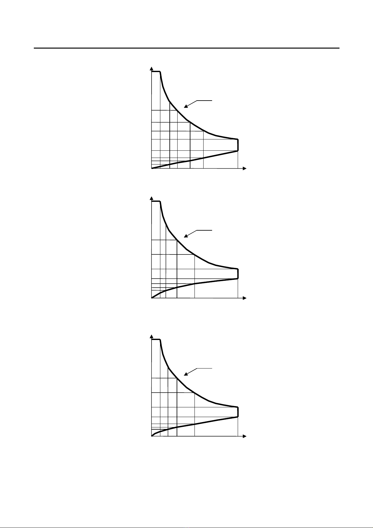
The 3350F Series Electronic Load is designed to test, evaluation and burn-in of DC power
supplies and batteries.
The 3350F Series electronic load can be operated for manual and GPIB operation. The
power contour of 3350F 1 00 Watts Electronic Load is shown in Fig 1-1~1-6, it has an input
from 0-1 0A, and 0 -60V current and voltage operating range respectively. The power
contour of 3350F series. The prodigit 3350F Series high power electronic Load can be
controlled locally at the front panel or remotely via computer over the GPIB/RS-
3 C/USB/LAN. Current (CC) mode, Constant Resistance (CR) mode, and Constant Voltage
(CV) mode. and Constant Power ( CP ) mode. The wide range dynamic load with
independent rise and fall current slew rate and analog programming input with arbitrary
wave-form input is available in Constant Current mode.

2 PRODIGIT
Fig 1-1 3350F Power Contour
Fig 1- 3351F Power Contour
1800W CONTOUR
120 A 30 40 60 90
60
30
20
0.4
Current
Voltage
0.1
15
0
0.15
0.225
1200W CONTOUR
120 A
20 30 60 80
60
20
15
0.
6
Current 0.1
10
0.3
0
0.4
Voltage
3350F Series Operation Manual 3
Fig 1-3 335 F Power Contour
Fig 1-4 3353F Power Contour
Fig 1-5 3354F Power Contour
1800W CONTOUR
360 A
30 60 90 180
60
20
10
0.
7
Current
0.1
5
0
0.3
Voltage
0.15
1800W CONTOUR
240 A 30 34.38 60 120
60
30
15
0.
7
Current
0.1
7.5
0
0.
3
5
0.175
Voltage
1200W CONTOUR
240 A
20 34.38 60 80 120
60
20
15
0.7
Current
0.1
5
0
10
0.23
0.35
Voltage

4 PRODIGIT
Fig 1-6 3356F Power Contour
CC Mode:
With the operating mode of constant current, the 3350F Series Electronic load will sink a
current in accordance with the programmed value regardless of the input voltage (see Fig.1-
7).
Fig 1-7 Constant Current mode
600W CONTOUR
120 A
10 30 60 90
60
1
0
6.66
0.
6
Current
0.1
5
0
0.225
Voltage
0.15
3350F Series Operation Manual 5
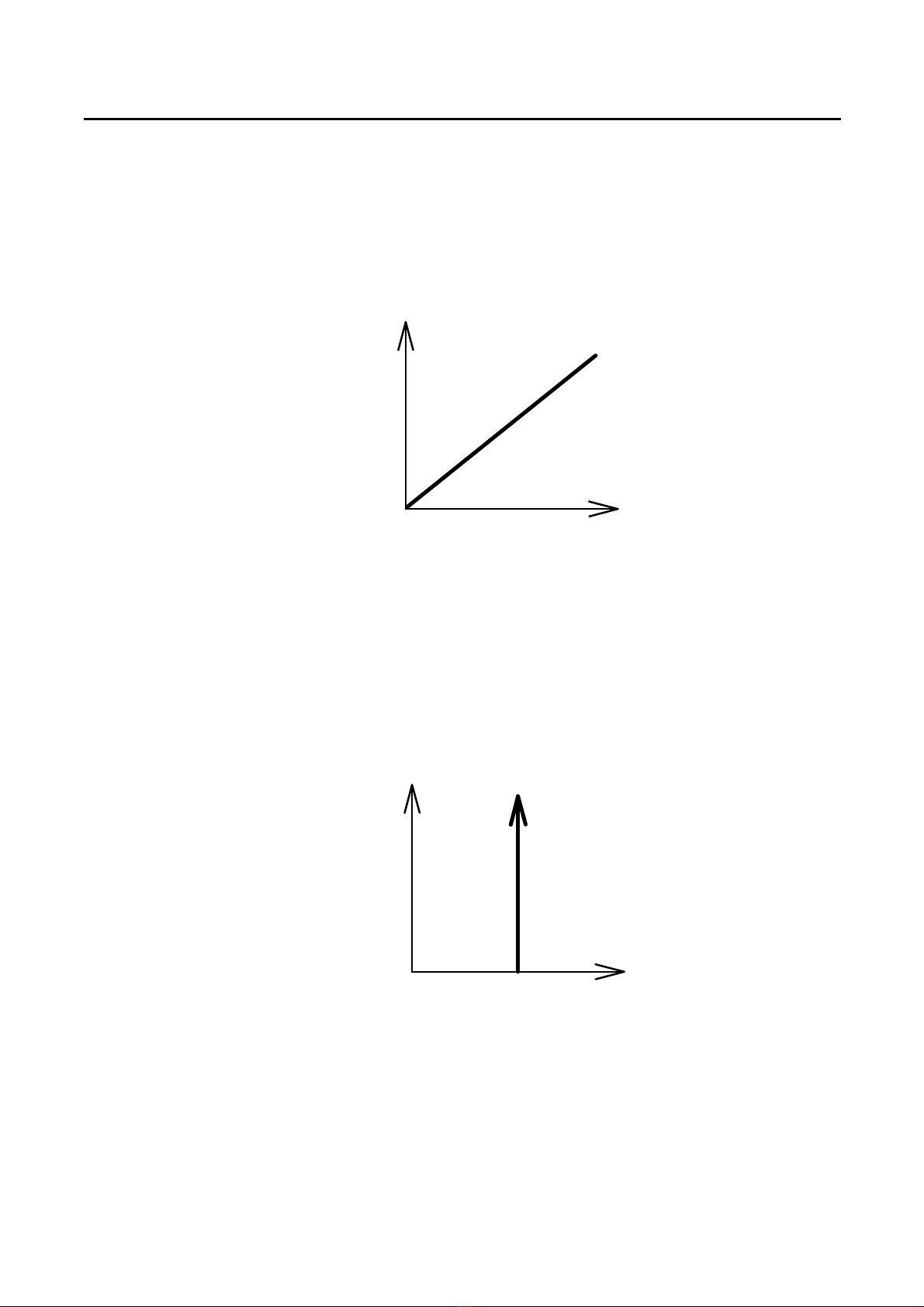
CR Mode:
At constant resistance mode, The 3350F Series Electronic Load will sink a current linearly
proportional to the load input voltage in accordance with the programmed resistance setting
(see Fig 1-8).
I
V
LOAD
CURRENT
INPUT VOLTAGE
RESISTANCE
SETTING
Fig 1-8 Constant Resistance mode
CV Mode:
At constant voltage mode, the 3350F Series Electronic Load will attempt to sink enough
current until the load input voltage is equaled to the programmed value (see Fig 1-9).
I
V
LOAD
CURRENT
INPUT VOLTAGE
VOLTAGE
SETTING
Fig 1-9 Constant Voltage mode
6 PRODIGIT
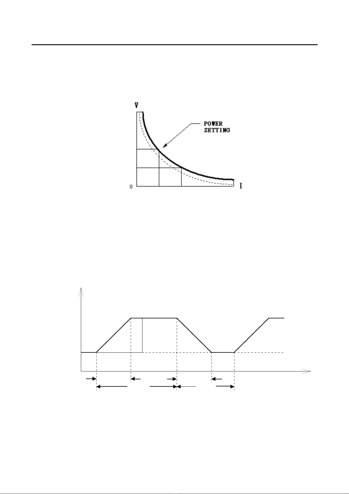
CP Mode:
At Constant Power mode, the 3350F Series Electronic Load will attempt to sink load power
(load voltage x load current) in accordance with the programmed power. (See Fig 1-10).
Fig 1-10 Constant Power mode
Dyna ic wave for definition:
There are six parameters to generate dynamic wave form or pulse wave form, the 3350F
Series Electronic Load will sink current from power source proportional to the dynamic wave
form, the dynamic wave form definition is shown in Fig 1-11. The period of dynamic wave form
is Thigh + Tlow, dynamic frequency = 1 / (Thigh + Tlow), the Duty cycle = Thigh / (Thigh + Tlow)
I
V
LOAD
CURRENT
RISE
SLEW RATE
HIGH LOAD
LOAD
LOW LOAD
LEVEL
THIGH TLOW
FALL SLEW RATE
Fig 1-11 Dynamic Wave form

3350F Series Operation Manual 7
The load current level and load status are can be set with Front panel on each module, GPIB
command. It is called manual operation and GPIB operation respectively, the load input
voltage and load current can be read back to computer through GPIB.
The GPIB operation is described in Chapter 4 GPIB operation.
Slew Rate:
Slew rate is defined as the change in current or voltage over time. A programmable slew rate
allows a controlled transition from one load setting to another to minimize induced voltage
drops on inductive power wiring, or to control induced transients on a test device (such as
would occur during power supply transient response testing).
In cases where the transition from one setting to another is large, the actual transition time can
be Calculated by dividing the voltage or current transition by the slew rate. The actual transition
time is Defined as the time required for the input to change from 10% to 90% or from 90% to
10% of the Programmed excursion. In cases where the transition from one setting to another is
small, the small Signal bandwidth of the load limits the minimum transition time for all
programmable slew rates. Because Of this limitation, the actual transition time is longer than
the expected time based on the slew rate, as Shown in Figure 1-1
Therefore, both minimum transition time and slew rate must be considered when determining
the actual transition time.
The minimum transition time for a given slew rate as about a 30% or greater load change, the
slew rate increases from the minimum transition time to the Maximum transition time at a 100%
load change. The actual transition time will be either the minimum transition time, or the total
slew time (transition divided by slew rate), whichever is longer.
Use the following formula to calculate the minimum transition time for a given slew rate
Min transition time = 36/slew rate (in amps/second)(7. us(36/5)*0.8(10%~90%)=5.76uS)
Use the following formula to calculate the maximum transition time for a given slew rate
Max transition time = 1 0/slew rate (in amps/second) ( 4us(1 0/5)*0.8(10%~90%)=19. uS)
EX. CCH= 4A, CCL=0A Slew Rate = 5A, The expected time is 3.84uS but the actual transition
time will be limited to 5.76uS((36/5)x0.8 )

8 PRODIGIT
Fig 1-1 Rise Time Transition Limitation
3350F Series Operation Manual 9
1-2. Features
1. .1. Flexible configuration of high power Electronic Load.
1. . . Fully GPIB control of Load condition setting and meter read back.
1. .3. Dual high accuracy & resolution 5 digit voltage and current meter.
1. .4. Built-in pulse generator includes wide Thigh/Tlow dynamic load range, independent
Rise/Fall load current slew rate control, and High/Low Load level.
1. .5. Controllable load current slew rate of load level change, load ON/OFF switch
change, and power supply turn ON.
1. .6. Short circuit test and current measure capability.
1. .7. Automatic voltage sense capability.
1. .8. Full protection from over power, over temperature, over voltage, and reverse polarity.
1. .9. Analog programming input capability at rear panel.
1-3. Accessories
1.3.1. 3350F series operation manual 1 PC
1.3. . M8 ROUND SCREW PCs
1.3.3. Vsense - Alligator Clip(red、black) Cable 1 PC
1.3.4. I-monitor - BNC Cable 1 PC
1.3.5. Power Cord 1 PC
1-4. Option
1.4.1. IEEE-488 cable (1 Meter)
1.4. . IEEE-488 cable ( Meter)
1.4.3. RS 3 interface
1.4.4. GPIB interface
1.4.5. USB interface + USB DRIVER CD
1.4.6. LAN interface + LAN DRIVER CD
1-5. Specifications
Table 1-1A 3350F Series Specifications
LI E 115V ± 10﹪ 230V ± 10﹪
FREQUE CY 50/60 Hz
FUSE T2A/250V(5×20 mm)
T1A/250V(5×20 mm)
AC I PUT
MAX. POWER
CO SUMPTIO
100 VA
DIME SIO S (W * H * D) 483 mm × 177 mm × 445Dmm/EA
WEIGHT ET:23.6 Kg

10 PRODIGIT
Model 3350F 3351F 3352F 3353F 3354F 3356F
Power 1200W 1800W 1200W 1800W 1800W 600W
Current 0~120A 0~120A 0~240A 0~240A 0~360A 0~120A
Voltage 0~60V 0~60V 0~60V 0~60V 0~60V 0~60V
Min. Operating Voltage 0.6V @ 120A 0.4V @ 120A 0.7V @ 240A 0.7V @ 240A 0.7V @ 360A 0.6V @ 120A
Constant Current Mode
ange *1 0~12A/120A 0~12A/120A 0~24A/240A 0~24A/240A 0~36A/360A 0~12A/120A
esolution 0.2mA/2mA 0.2mA/2mA 0.4mA/4mA 0.4mA/4mA 0.6mA/6mA 0.2mA/2mA
Accuracy ± 0.1% OF (Setting + ange)
Constant Resistance Mode
ange 0.0083~0.5~30KΩ
0.0083~0.5~30KΩ
0.0041~0.25~15KΩ
0.0041~0.25~15KΩ
0.0027~0.167~10KΩ
0.0083~0.5~30KΩ
esolution 0.0083mΩ/0.033mS
0.0083mΩ/0.033mS
0.0041mΩ/0.066mS
0.0041mΩ/0.066mS
0.0027mΩ/0.1mS 0.0083mΩ/0.033mS
Accuracy ± 0.2% OF (Setting + ange)
Constant Voltage Mode
ange 6V/60V
esolution 0.1mV/1mV 0.1mV/1mV 0.1mV/1mV 0.1mV/1mV 0.1mV/1mV 0.1mV/1mV
Accuracy ± 0.05% OF (Setting + ange)
Constant Power Mode
ange 120W/1200W 180W/1800W 120W/1200W 180W/1800W 180W/1800W 60W/600W
esolution 2mW/20mW 3mW/30mW 2mW/20mW 3mW/30mW 3mW/30mW 1mW/10mW
Accuracy ± 0.5% OF (Setting + ange)
Dynamic Mode CC
Timing
Thigh & Tlow 0.050~9.999 / 99.99 / 999.9 / 9999mS
esolution 0.001 / 0.01 / 0.1 / 1mS
Accuracy 1uS/10uS/100uS/1mS + 50ppm
Slew rate 8mA~500mA/uS
80mA~5000mA/uS
8mA~500mA/uS
80mA~5000mA/uS
0.016A~1A/uS
0.16A~10A/uS
0.016A~1A/uS
0.16A~10A/uS
0.024A~1.5A/uS
0.24A~15A/uS
8mA~500mA/uS
80mA~5000mA/uS
esolution 2/20mA/uS 2/20mA/uS 0.004/0.04A/uS 0.004/0.04A/uS 0.006/0.06A/uS 2m/20mA/uS
Accuracy (5% of setting) ± 10 uS
Min. ise Time 24uS(typical)
Current
ange *2 12A/120A 12A/120A 24A/240A 24A/240A 36A/360A 12A/120A
esolution 0.2mA/2mA 0.2mA/2mA 0.4mA/4mA 0.4mA/4mA 0.6mA/6mA 0.2mA/2mA
Accuracy ± 0.1% OF (Setting + ange)
Measurement
Voltage Read Back
ange (5 Digital) 0~6V/60V 0~6V/60V 0~6V/60V 0~6V/60V 0~6V/60V 0~6V/60V
esolution 0.1mV/1mV 0.1mV/1mV 0.1mV/1mV 0.1mV/1mV 0.1mV/1mV 0.1mV/1mV
Accuracy ± 0.025% OF ( eading + ange)
Current Read Back
ange (5 Digital) 0~12A/120A 0~12A/120A 0~24A/240A 0~24A/240A 0~36A/360A 0~12A/120A
esolution 0.2mA/2mA 0.2mA/2mA 0.4mA/4mA 0.4mA/4mA 0.6mA/6mA 0.2mA/2mA
Accuracy ± 0.1% OF ( eading + ange)
Power Read Back
ange (5 Digital) 0~1200W 0~1800W 0~1200W 0~1800W 0~1800W 0~600W
esolution 0.01W
Accuracy ± 0.125% OF ( eading + ange)
Program mode(Mainframe)
Sequence No. F1~9/16 Steps
T1/T2 (Dwell) 0.1S~9.9S/ epeat 9999
Load Setting(External
Programming) 0~10V for CC mode F.S.
GO/NG Check Voltage/Current/Power
Protections
Over Power 105% of ated Power
Over Current 105% of ated Current
Over Voltage 105% of ated Voltage
Over Temp. Yes
Interface(Mainframe)
S-232 Optional
GPIB Optional
USB Optional

3350F Series Operation Manual 11
Ethernet Optional
Others
Load ON Voltage
ange 0.1~25.0V
esolution 0.1V
Accuracy 1% of Setting + 0.25V
Load OFF Voltage
ange 0~25V
esolution Same as Voltage Meter
Accuracy Same as Voltage Meter
General
Short Circuit
Current 120A 120A 240A 240A 360A 120A
Temperature Coefficient 100ppm/℃(typical)
Power 100Wmax 100Wmax 100Wmax 100Wmax 100Wmax 100Wmax
Operating Temperature *2 0~40℃
Dimension(HxWxD) 177 x 440 x 445 mm/6.97x17.3x17.5 inch
Weight 19.4 kg / 42.77 lbs
23.6 Kg/52.03 lbs 19.4 kg / 42.77 lbs
23.6 Kg/52.03 lbs 23.6 Kg/52.03 lbs 15.2 Kg/33.51 lbs
Safety & EMC CE
Table 1-1B 3350F Series Specifications
This manual suits for next models
6
Table of contents
Other Prodigit Power Supply manuals


