Produal KRM-1 User manual

USER GUIDE
KRM-1 & KRM-2
V2.0 (05.11.2015)
1 (8)
Produal Oy Keltakalliontie 18, 48770 Kotka FINLAND Tel: +358-10-219 9100 / Fax: +358-5-230 9210 [email protected]i www.produal.com
Information is subject to change without prior notice.
5 d
h
3 d
h
5 d
h
SENSOR CONSTRUCTION
A. Electronics.
B. Upper casing with seal.
C. Lower housing with seal
D. Adapter plate with gasket.
E. Optical smoke sensor.
F. Rubber bushing (only for insulated or circular ducts).
G. Air flow in a duct
H. Measuring tube (max. length 3 m).
I. End cap
ASSEMBLY
Device assembly, wiring and commissioning can only be carried out by qualified professionals. Always
make the connections while the power is switched off.
Positioning of the sensor
The KRM is to be positioned in accordance with the current local state regulations on ventilation systems. Reliable
smoke detection must be guaranteed. Depending on the cross section of the ventilation duct the air collecting tube
may be cut to a length of 160 mm. This minimum length of 160 mm must not be undercut. This way, up to <100 mm ø
can be monitored in conjunction with the FP-KRM fitting plate. In the ideal case, install the KRM when structurally
possible, where flow meters, etc. are normally attached, so there is a laminar airflow along the measuring tube.
The KRM is to be installed so that the air collecting tube is constantly in the air stream. In horizontal ventilation ducts
the KRM including air collecting tube should be installed in the upper third of the ventilation ducts or at the top of the
ventilation ducts, if this is structurally possible.
Example of positioning after the
change of air duct direction
Air outlet Example of positioning after air
outlets.
Where there are large temperature differences, outdoors for example, or in places that are dependent on outside
temperature (roof, attic), the air duct smoke sensor has to be insulated.
DC
A
E
G
F
H
I
B
USER GUIDE
KRM-1 & KRM-2
2 (8)
Produal Oy Keltakalliontie 18, 48770 Kotka FINLAND Tel: +358-10-219 9100 / Fax: +358-5-230 9210 [email protected]i www.produal.com
Information is subject to change without prior notice.
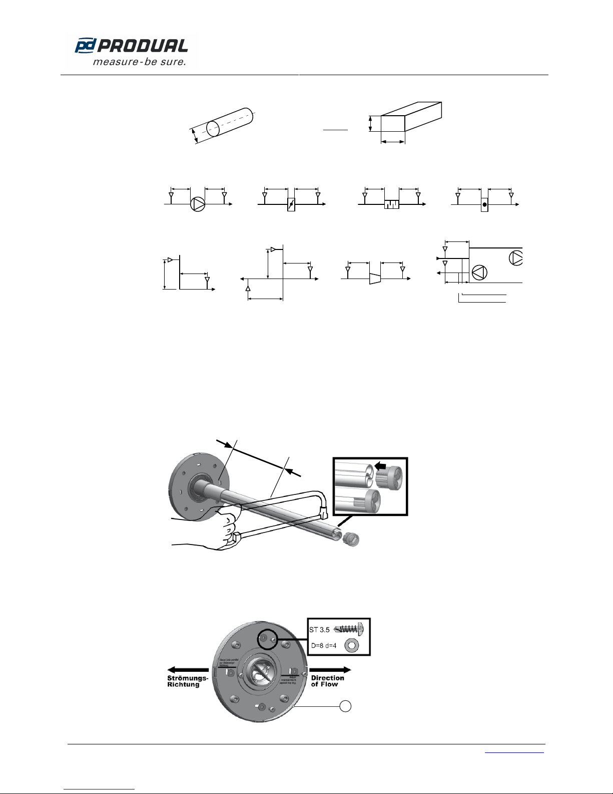
Hydraulic diameters, dh
dh
=2xHxW
H+W
HW
dh=D
øD
Round duct Rectangular duct
Example of positioning (recommendations):
MIN 3xd
h
MIN 5xd
h
MIN 3xd
h
MIN 5xd
h
MIN 3xd
h
MIN 5xd
h
MIN 3xd
h
MIN 5xd
h
KR
M
KRMKRMKRMKRMKRMKRMKRM
Fan Damper Silencer Heater
KRM KRM
KRM KRM KRM
KRM
KRM
KRM
MIN 5xd
h
MIN 3xd
h
MIN 5xd
h
MIN 5xd
h
MIN 3xd
h
MIN 3xd
h
MIN 5xd
h
MIN 5xd
h
MIN 3xd
h
Exhaust air
Supply air
Change in air duct
direction Air duct forking Air duct narrowing / air
duct enlargement Air duct device
Mounting procedure
1. Drill a hole Ø 43…44 mm in diameter at the intended mounting location.
NOTE: Installation of the measuring tube is possible either from the top, bottom or side of the channel for all duct
cross-sections (for round ducts as well).
2. Determine how long the measuring tube must be. If necessary, shorten the tube. Put the end plug back on up to
the stop collar.
min. 160 mm
IMPORTANT: Operation without end plug not permitted.
3. Determine the direction of flow and fit the adapter plate (A) so that the line on the adapter plate under the text
”Strömungsrichtung” is parallel to the flow direction. Four self-tapping screws serve for attaching it to the sheet
metal duct (not included in delivery).
A
USER GUIDE
KRM-1 & KRM-2
3 (8)
Produal Oy Keltakalliontie 18, 48770 Kotka FINLAND Tel: +358-10-219 9100 / Fax: +358-5-230 9210 [email protected]i www.produal.com
Information is subject to change without prior notice.
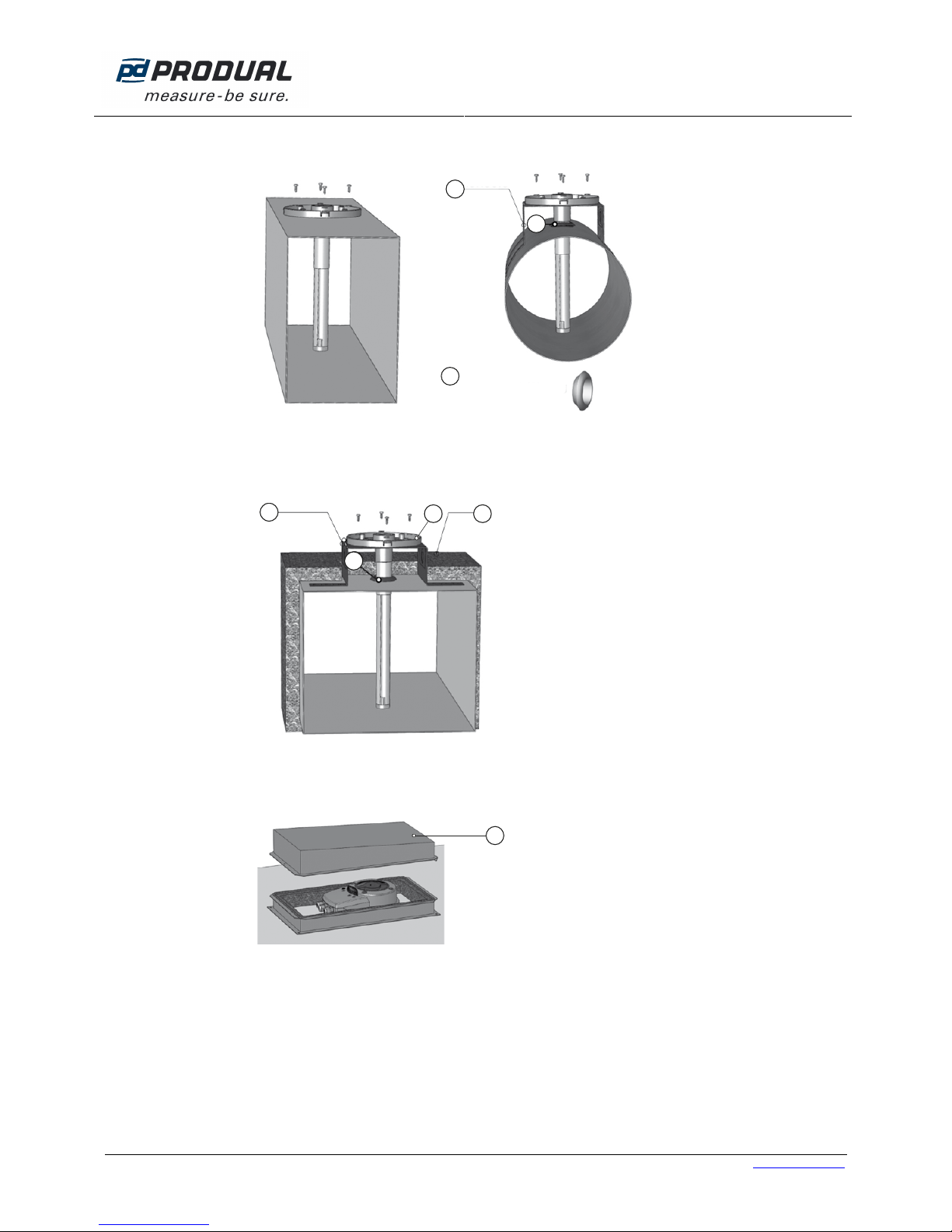
4. Installation on a rectangular air duct, see picture below. When installing on a circular air duct, use KS fitting plate
(B) and rubber bushing (C).
C
B
C
5. When installing on the air ducts with insulation, use the rubber bushing and insert it into opening in the air duct.
Install the fitting plate (B). Insert the assembled adapter plate (A) into the measuring tube by sliding the measur-
ing tube through the grommet, and screw the adapter plate onto the fitting plate (B) using the 4 self-tapping
screws. Install the sensor with fitting plate into air duct. Then the insulation (D) can be installed.
BD
C
A
6. When installing sensor outdoors or in cold environment, special WDG type housing (E) should be used. Housing
prevents the warm air in the smoke detector duct from condensing. The interior of the housing is insulated with
foam rubber.
E
Rubber
bushing, inner oute
r
USER GUIDE
KRM-1 & KRM-2
4 (8)
Produal Oy Keltakalliontie 18, 48770 Kotka FINLAND Tel: +358-10-219 9100 / Fax: +358-5-230 9210 [email protected]i www.produal.com
Information is subject to change without prior notice.
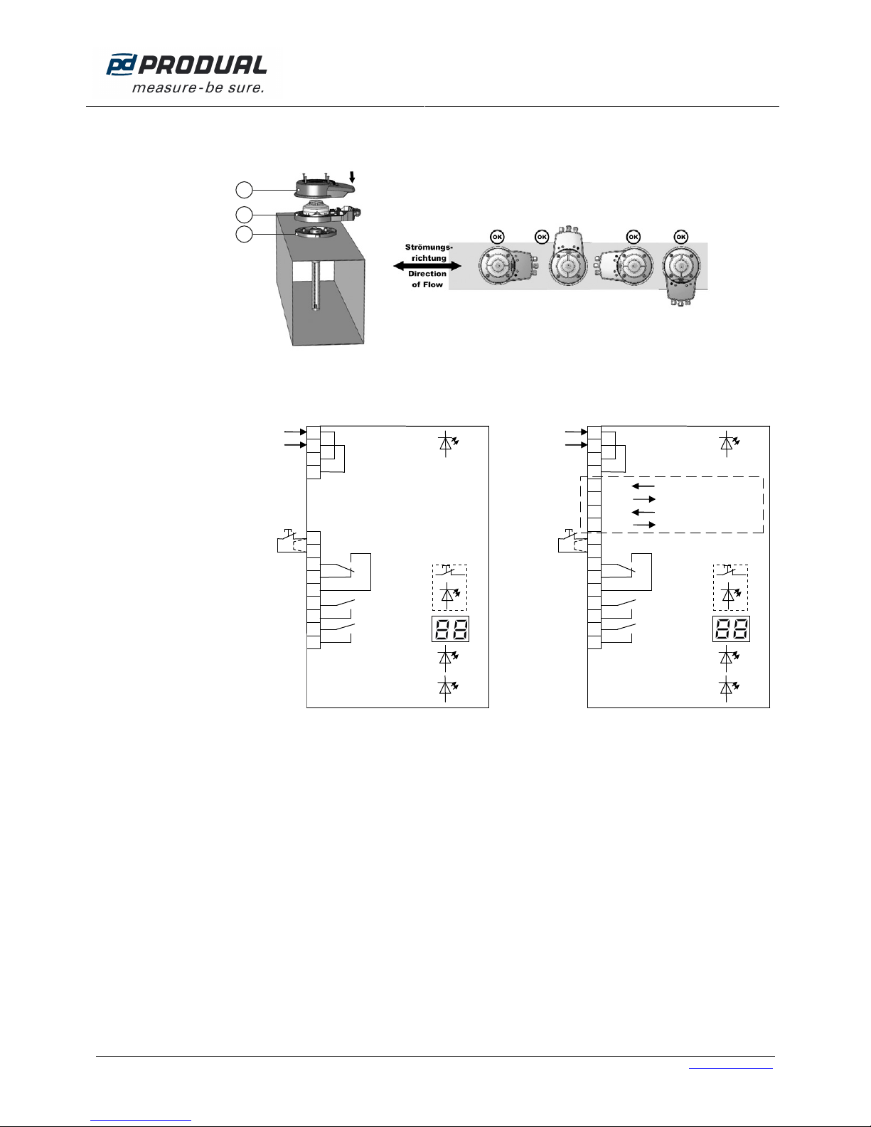
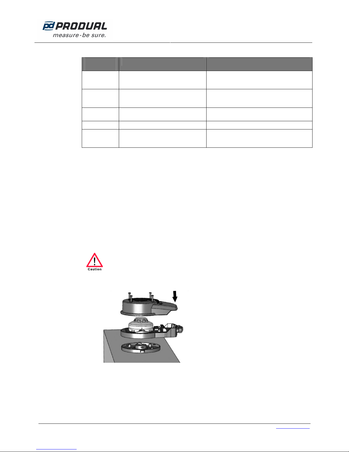
7. Install the housing (F) with the sensor (G). Attach the housing bottom part with the electronics and sensor to the
adapter plate (A). The housing can be attached at increments of 90°. The direction of the housing has no effect
on the measurement result. You can align the housing with the sensor optimally.
F
G
A
8. Wire the unit according to the applicable circuit diagram.
Power supply
230 Vac
Test/Reset
(NC contact)
9
10
11
12
13
14
15
green
16
17
yellow
blue
Smoke alarm
Smoke alarm
Service signal
Contamination
red
Test/Reset
3
4
Power supply
230 Vac
1
2
Power supply
24 Vac/dc
Test/Reset
(NC contact)
9
10
11
12
13
14
15
green
16
17
yellow
blue
Smoke alarm
Smoke alarm
Service signal
Contamination
red
Test/Reset
3
4
Power supply
24 Vac/dc
1
2
5
6
7
8
Bus B
Bus B
Bus A
Bus A
RS485
(for information)
MOD / BAC models
KRM-1 KRM-2, KRM-2-MOD, KRM-2-BAC
NOTES
The cable jacket for field wire connecting must be done as near as possible to the terminal block. For wires
longer than 10 mm, the wire must be fixed by a cable clip near the terminal block or insulated in pairs with a
suitably protective tube.
Test/reset (terminal 9 +10): if bridge circuit is removed, a floating NC contact must be connected.
The floating switching contacts (terminals 11 – 17) are to be assigned as uniformly as possible to an
installation category according to EN 60730-1. These switching contacts are only to be used for 230 Vac or
24 Vac/dc, no combinations are permitted unless at least one contact between the potentials remains
unassigned. A mixed connection of safety extra-low voltage (SELV) and low voltage must not occur. The
assembly may only be operated on one mains phase. The voltage / safeguard activation is to be provided
on site. KRM-1 (230 V versions) with a fuse of 16 A; KRM-2 (24 V version) with a fuse of 4 A

USER GUIDE
KRM-1 & KRM-2
5 (8)
Produal Oy Keltakalliontie 18, 48770 Kotka FINLAND Tel: +358-10-219 9100 / Fax: +358-5-230 9210 [email protected]i www.produal.com
Information is subject to change without prior notice.
Programming the Bus address for the KRM-2-MOD / KRM-2-BAC
Press buttons T3+T4 on the circuit board (to the right, next to the
display) at the same time, so that the display changes from
contamination level to show the bus address (the display will flash).
Press button T3 or T4 to adjust the desired address (1 – 99) and
confirm with simultaneous pressing of T3 and T4. A device return
automatically follows after 3 seconds without pressing a key.
SENSOR OPERATIONAL TESTING
After completing the installation work, doing proper wiring and applying power, the duct smoke sensor is operational.
1. The green LED (H) illuminates.
2. By pressing the alarm / reset button (D), an initial simple functional test can be made. All LEDs must light up and
all the relays drop out. The units connected to the relays are activated! The display (G) indicates the current
degree of sensor contamination. If the button is released, all LEDs will go out except for LED (H), which shows
the supply voltage and the relays functions.
D
GH
J
D
J
3. For testing the smoke sensor the housing must not be opened. It has a self-closing test opening (J) in the centre
of the transparent cover. Use test gas spray. Insert the test spray‘s tube fully into the test opening (appx. 1.5 mm
deep) and release as much test gas as needed until the smoke sensor activates. Please do not spray too much,
otherwise the smoke sensor may display a higher degree of contamination at the next start / reset. The alarm /
reset button lights up, the relays drop out. The electronics are on alert and locked. To release the alarm / reset
button must be pressed. At the time of the reset, the sensor must be free of smoke and test gas. Should there still
be test gas in the chamber a higher degree of contamination will appear. In this case, after some time perform a
reset by disconnecting from the power or by an external reset, or if necessary, remove the housing cover and
blow out the smoke detector.
DISPLAY AND OPERATION FOR DUCT SMOKE SENSOR
A. LED smoke alarm (red).
B. LED failure (yellow).
C. LED alarm (red) and Alarm / reset button.
D. LED alarm (red) and alarm/reset button.
Failure reset: briefly press button and release.
Alarm reset: Press button for at least 2 seconds
until the red LED goes out.
E. LED smoke alarm (red).
F. Display indicator (contamination in % or status).
G. LED power supply (green).
H. LED air flow (blue) lights up when there is insufficient flow
A
B
C
D
E
F
G
H
USER GUIDE
KRM-1 & KRM-2
6 (8)
Produal Oy Keltakalliontie 18, 48770 Kotka FINLAND Tel: +358-10-219 9100 / Fax: +358-5-230 9210 [email protected]i www.produal.com
Information is subject to change without prior notice.
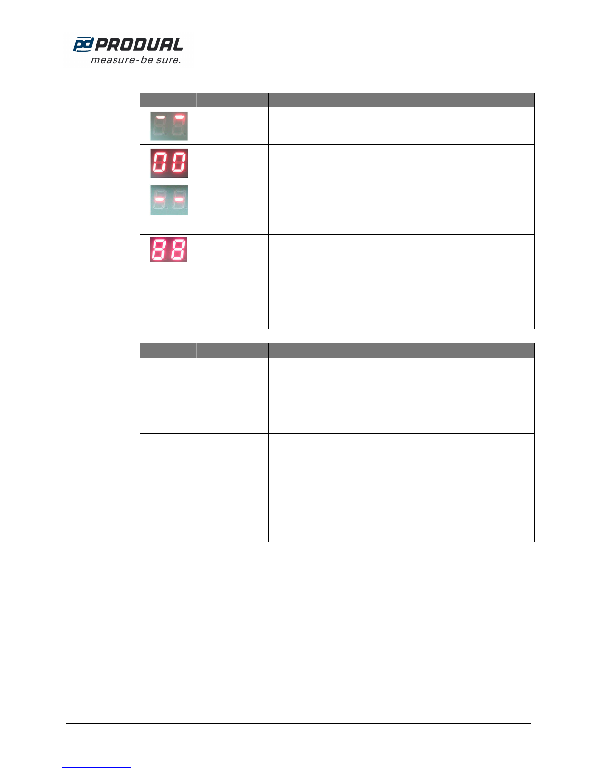
Display Meaning Explanation
Start / calibration Shortly after starting the software version is displayed (4 digits), e. g. 00 then
20 = Software 0020. Thereafter, the rotating segment display follows at start
up or after a power failure.
Contamination in
00 – 99 % Flashes starting at 70 % (relay contamination drops out); at 99 % with display
LED alarm.
Failure e.g. Missing smoke detector, disrupted communication with the smoke
detector, processor failure.
Failure LED (B) & alarm LED (A) light up at the same time
Troubleshooting: change the detector and confirm by pressing the alarm /
reset button (D).
+
all LEDs on
the circuit
board light up
Confirmation reset
/ new start If alarm / reset button (D) is pressed for more than 8 seconds, or if bridge
circuit / terminal 9 / 10 is open (missing bridge circuit or remote reset). Display
goes out after releasing the alarm / reset button or closing the bridge circuit
between terminal 9 + 10.
00 – 99
flashing BUS address Display only with MOD/BAC versions after pressing the address buttons T3
and T4 directly on the circuit board.
LEDs Meaning Explanation
Alarm / reset
(red) Smoke alarm or
failure Reset after failure:
Briefly press alarm / reset button. KRM immediately restarts.
Reset after alarm:
Press and hold the alarm / reset button for at least 2 seconds until the red
alarm LED in the button goes out. Do not release it until then. KRM will start
again only after release. As long as the alarm / reset LED flashes when the
button is pressed, the smoke sensor is still filled with test gas / test spray /
smoke, and can not be reset. In that case blow the sensor out or wait.
Failure
(yellow) Defective circuit
board or missing
smoke alarm
Check / replace circuit board or smoke detector.
Smoke alarm
(2 x red) Smoke alarm or
contamination 99
%
Red LEDs directly on the smoke detector. LEDs permanently on until reset has
taken place.
Power (green) Supply voltage is
on Green LED lights up if supply voltage is on.
Air flow (blue) Air flow is too low Blue LED lights up when air flow is too low. Check smoke detector position in
the duct, check sampling tube for contamination / clean if necessary.
USER GUIDE
KRM-1 & KRM-2
7 (8)
Produal Oy Keltakalliontie 18, 48770 Kotka FINLAND Tel: +358-10-219 9100 / Fax: +358-5-230 9210 [email protected]i www.produal.com
Information is subject to change without prior notice.
Behaviour of the alarm relay and fault relay and displays, plus reset options
Valid with
software 0020 Smoke alarm Device failure / missing detector
Alarm relay,
connectors
11/12/13 Drops out Drops out
Alarm relay,
connectors
14/15 Drops out Drops out
LED
Alarm / Reset Lights up Lights up
LED failure Does not light up Lights up
Alarm reset or
failure reset With power interruption, alarm button or
with terminal 9 / 10 provided that sensing
chamber is free.
With power interruption, alarm button or with
terminal 9/10 provided that sensing chamber is free
+ disturbance has ceased.
MAINTENANCE AND REPAIR
In order to ensure good performance over a longer period of time the smoke alarms must be tested at least once a
year. Without maintenance, and depending on environmental conditions, the sensor will become dirty sooner or later,
and after a certain time will trigger an alarm, which is a false alarm.
NOTE: All types will give a specific maintenance requirement signal at a contamination level of 70 % (display flashes,
relay contamination drops out). There is a contact available for this “contamination” signal (terminals 16/17), and it
should be connected to the automation station. From a 70 % contamination level or higher the smoke sensor must be
changed.
Maintenance and repair procedure
If, due to operational specifications short term shutdowns cannot be tolerated, measures must be taken to prevent this;
if necessary by placing a bridge over the alarm contact, but remembering to remove it after completion of the service
work. After maintenance work, a complete functionality test must be carried out. If defects have appeared they must
be removed immediately.
Before opening the housing, turn off all supply voltages – The housing may only be opened by a qualified
electrician. Supply and switching voltages must be observed.
1. The smoke detector is accessible by removing the cover.
2. By turning the white detector on the base by about 20° to anticlockwise the sensor can be unscrewed. If it is too
dirty (indicator >70 %), and no later than the prescribed standard of exchange cycles, the sensor must be
removed and exchanged for a new sensor.
3. If necessary, clean the cover, measuring tube and the inner housing.
4. Check the electrical connections, possibly tightening the terminals. Make visual inspection and clean the
electrical circuit board if necessary, as well as the inner housing. Check all seals.
5. Assemble all parts.

USER GUIDE
KRM-1 & KRM-2
8 (8)
Produal Oy Keltakalliontie 18, 48770 Kotka FINLAND Tel: +358-10-219 9100 / Fax: +358-5-230 9210 [email protected]i www.produal.com
Information is subject to change without prior notice.
6. Test system by triggering the smoke detector with test spray.
D
J
7. Check with the operator about the function of the downstream systems and components, such as:
Turning off of fans.
Closing of flaps.
Notification to the building automation system.
When checking network failure and recovery, does the sensor return to its normal function and does it
unlock again from the state ”smoke alarm” and return to its normal function when there is no longer any
present?
Release is possible by pressing the reset button with brief power interruptions.
This manual suits for next models
1
Table of contents
Popular Smoke Alarm manuals by other brands

Mircom
Mircom MIX-2251AP Installation and maintenance instructions

Xtralis
Xtralis XAS-2-US Product guide

System Sensor
System Sensor Inovair Flex D4240 Installation and maintenance instructions

Greenheck
Greenheck Combination Fire Smoke Damper SEFSDR-511 Specifications

Firehawk
Firehawk FHB1OW user manual

Landmann
Landmann Smoky Mountain Great Outdoors 3625GD owner's manual


