FIRERAY 50/100 11
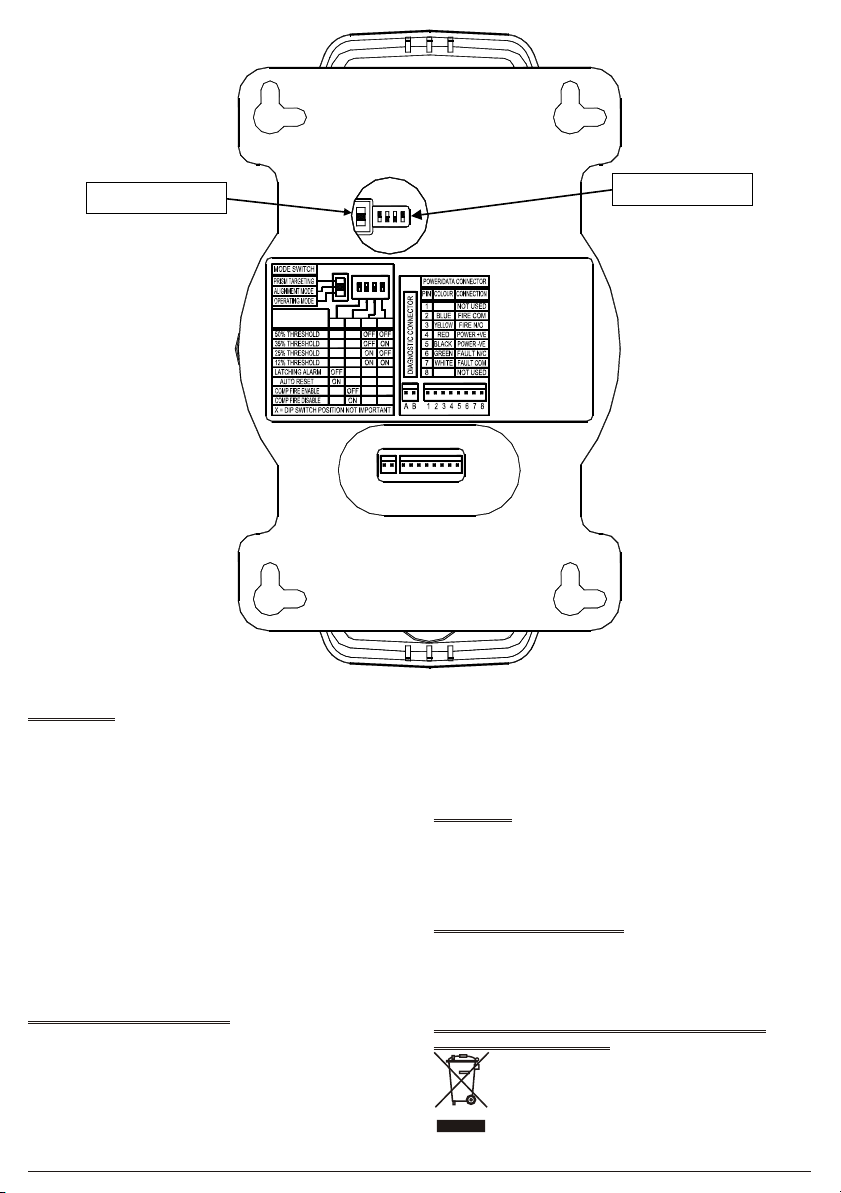
Switch 1 selects latching or auto reset for the alarm relay. Auto reset is the
factory default setting. See Fig.12 for setting options.
Using the mode switch at the back of the unit, (See fig.12 page 16) select
Prism Targeting Mode (Switch will be in its upper position).
The Detector Head Assembly is now ready for installation. If switches 1 to 4
require resetting after installation, a power down reset is required (entering
into Prism Targeting/Alignment Mode can also be used as a reset).
4.1. Detector Head Assembly Installation.
Remove the outer cover before installation; this is only to prevent the cover
becoming dislodged during handling.
!Do not mount on plasterboard, cladded walls, wood or similar ma-
terials, as these surfaces do, and will move.
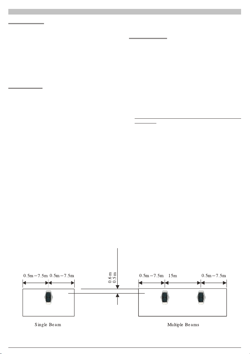
Determine the position of the Head Assembly, which must be mounted on a
solid structure. Ensure that there is a clear line of sight (0.5 metres radius
around the beam) to the proposed position of the prism(s), which is to be
mounted on a solid structure between 5 and 100 metres directly opposite the
Detector (range and number of prisms dependent on model).
Using the template provided mark and install all 4 fixing points to the struc-
ture. The rear mounting plate of the Detector Head Assembly is provided
with 4 keyhole slotted apertures to allow for easy installation onto the 4 fixing
points.
Replace the outer cover.
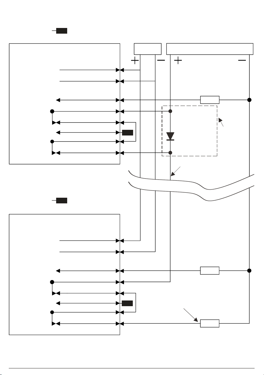
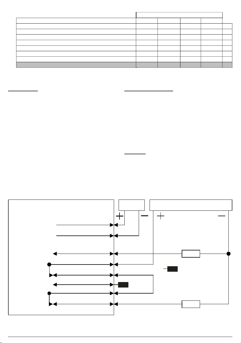
Terminate the field wiring. See section 8.
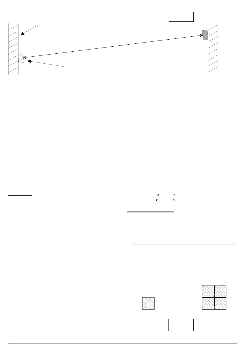
4.2. Prism(s) Installation.
Mount the Prism(s) on a solid structure, 90º to the beam path, between 5 to
50 metres (for the 50 metre Detector), and 50 to 100 metres (for the 100
metre Detector) directly opposite the Detector.
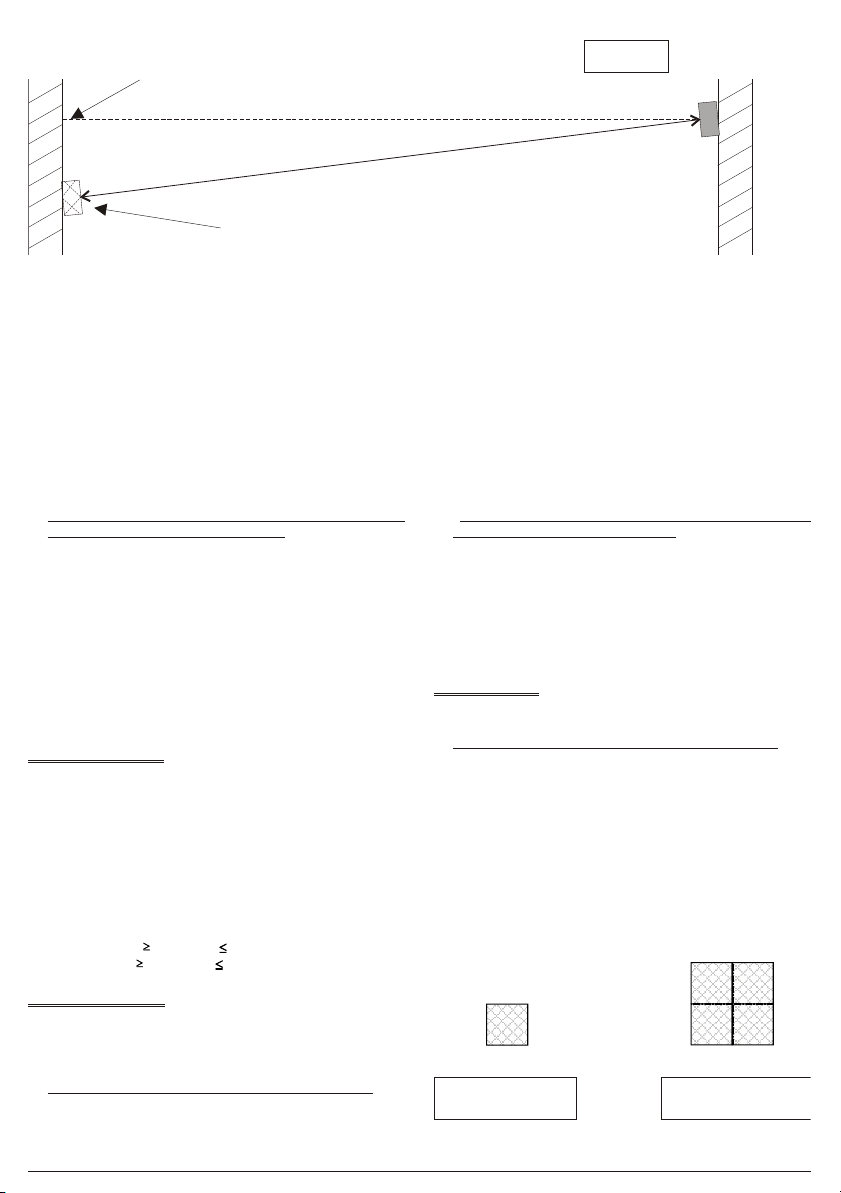
+If the detector is to be placed in an atrium, or near glass/polished surfa-
ces, the prism(s) should be offset from the central line of sight (Refer to
Section 3.2).
Ensure that there is a clear line of sight to the Detector, taking care that no
moving objects i.e. doors, mechanical lifting equipment etc, will interfere
with the beam path between the Detector and Prism(s).
+Note:On ranges of 5 metres and 50 metres use a 50 metre Detector.
On ranges of 50 metres and 100 metres use a 100 metre Detector.
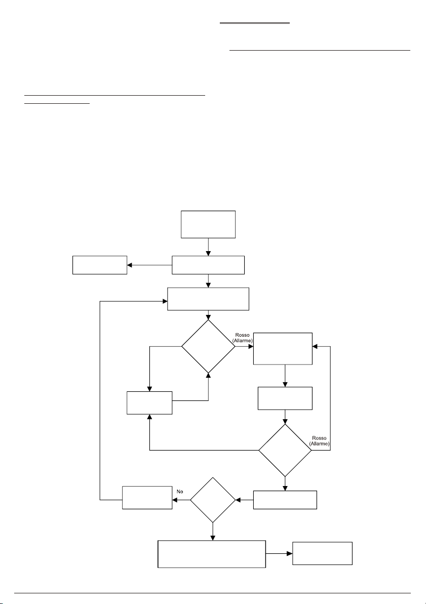
5. Prism Targeting Mode.
Apply power to the Detector. There is a 5 seconds pre-charge delay after
power is applied to allow the internal circuits to stabilise correctly. After this
period the RED indicator will flash once to indicate that the model is a 50
metre Detector or will flash twice to indicate a 100 metre Detector.
!Do not remove the detector from the wall during this action.
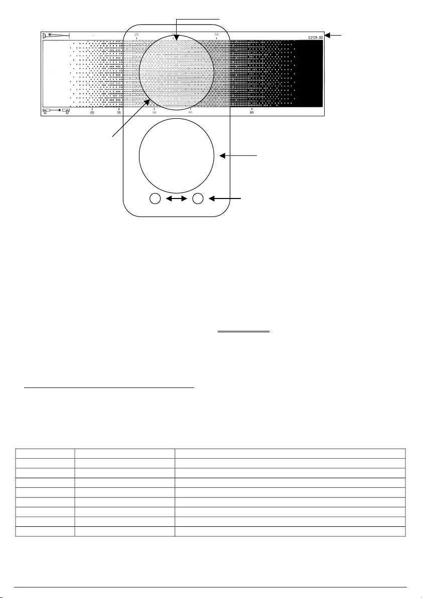
Mechanical alignment is provided by two adjustment thumb wheels on two
sides of the Detector, positioned just behind the Detector Head cover. Ad-
justment is achievable in both vertical and horizontal axis.
Find the prism(s) by adjusting the horizontal and vertical thumbwheels until
the FAULT indicator is continuously to determine the target position.
The FAULT indicator will be OFF when no signal is being received. It will
then flash at an incrementing rate to determine the target position. The
faster the flash rate (the stronger the signal), the nearer you are to the target
(prism). As the beam is moved across the prism the flash rate will increase,
go solid and then go back to a flash rate. A continuous LED indicates that the
prism has been detected. Find the halfway point for each axis, by counting
the amount of turns of the thumbwheel it takes for the LED to go from just
flashing to on, to on to just flashing. At this point reverse the direction of rota-
tion, and turn the thumbwheel half the amount of turns counted.
!It is essential to test that the prism(s), and not another surface, is
reflecting the signal back to the detector.
This can easily be confirmed by covering the prism(s) with a non-reflecting
surface, and confirm that the FAULT indicator changes state, either the
FAULT indicator is OFF or flashing very slowly.
If an area has a large amount of reflective surface along the beam path, do
not at first fit the reflector. When in targeting mode ensure that the AMBER
LED does not flash. Then fit the reflector in a position that turns the AMBER
LED constantly on.
6. Alignment Mode.
6.1. Enabling Alignment Mode.
!Do not remove the detector from the wall during this action.
Using the mode switch (See fig. 12, page 16) select Alignment Mode (Move
switch to the middle position).
6.2. Adjustment in Alignment Mode.
The Detector will automatically adjust its infrared beam power and receiver
sensitivity to give an optimum receiver signal strength (100%).
The alignment progress is indicated by the colour and state of the indicator
lamp on the front of the Detector.
ØFLASHING ALARM (Red LED)
The Detector is receiving a high signal (>100%) and is attempting to re-
duce the infrared power output to compensate.
1 Reflective Prism for
the 50 metre Detector
4 Reflective Prisms for
the 100 metre Detector
FIG. 7 Reflective Prism(s)
Offset Prism position and beam path
Normal Prism position and
central line of sight
Detector
head
Plan View
FIG.6