manuals.online logo
Brands
  1. Home
  2. •
  3. Brands
  4. •
  5. HST
  6. •
  7. Smoke Alarm
  8. •
  9. HST HD103B User manual

HST HD103B User manual

INSTALLATION AND MAINTENANCE INSTRUCTIONS
HD103B
Conventional Photoelectric S oke& Heat Detector
SPECIFICATIONS
Operating Voltage Range: 9 to 28VDC Volts Non-polarized
Standby Current: ≤60 A @ 24 VDC
Maximum Alarm Current (LED on: ) ≤30mA @ 24 VDC
Operating Humidity Range: 10% to 93% Relative Humidity, Non-condensing
Operating Temperature Range: 14°F to 120°F (-10°C to 49°C)
Smoke Sensitivity: 1.06±.26%FT.
Fixed Temperature Rating: 135°F (57°C)
Rate of Rise Detection: Responds to greater than 15°F/min
Height: 2.2˝ (55 mm) installed in Base
Diameter: 4.0˝ (103 mm)
Weight: 5.5 oz. (155 g)
INSTALLATION
BEFORE INSTALLING
NOTICE: This manual should be left with the
owner/user of this equipment.
IMPORTANT: The detector must be tested and
maintained regularly following NFPA 72 requirements.
The detector should be cleaned at least once a year.
GENERAL DESCRIPTION
The device is photoelectronic detector uses a state of-the-
art optical sensing chamber. This detector is designed to
provide open area protection and to be used with most
conventional fire alarm control panel.
Two LEDs on each detector provide local 360° visible
alarm indication. They flash every 3~5 seconds indicating
that power is applied and the detector is working
properly. The LEDs latch on in alarm. LEDs will be off
when a trouble condition exists indicating that the
detector sensitivity is outside the listed limit. The alarm
can be reset only by a momentary power interruption.
INSTALLATION
NOTE: All wiring must conform to applicable local
codes, ordinances, and regulations.
NOTE: Verify that all detector bases are installed, that
the initiating-device circuits have been tested, and that the
wiring is correct.
Remove power from initiating-device circuits before
insta ing detectors.
1. Wire the sensor base per the wiring diagram, Figure 1.
2. Install the sensor into the sensor base. Push the sensor
into the base while turning it clockwise to secure it in
place.
3. After all sensors have been installed, apply power to
the control unit.
4. Test the sensor(s) as described in the TESTING
section of this manual.
5. Notify the proper authorities that the system is in
60mmm
�
C o n v e n t i o n a l F i r e
A l a r m C o n t r o l P a n e l
E O L
R e s i s t o r
U n p o a r i z e d w i r e
Z O N E + B a s e t e r m i n a l , 3 a r e s h o r t c i r c u i t i n s i d e t h e d e t e c t o r
Z O N E -
R e m o t e L E D
R e m o t e L E D
operation.
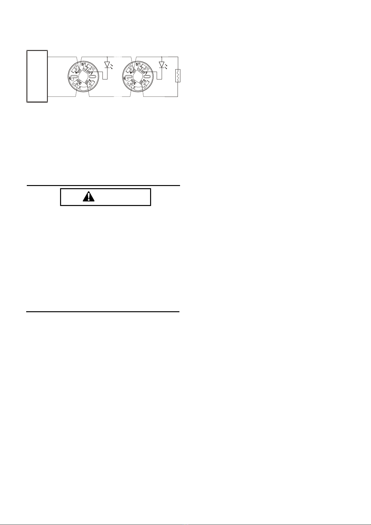
Figure 1. Wiring diagram:
Warning :Forbid connect 4VDC directly without current-limiting
resistance. Otherwise, the detector would be burnt out.
Dust covers are an effective way to imit the entry of
dust into smoke detector sensing chambers. However,
they may not comp ete y prevent airborne dust
partic es from entering the detector. Therefore, We
recommends the remova of detectors before
beginning construction or other dust producing
activity.
Be sure to remove the dust covers from any sensors
that were eft in p ace during construction as part of
returning the system to service.
TAMPER-RESISTANCE
Models DG311 include a tamper-resistant capability that
prevents their removal from the bracket without the use
of a tool.
TESTING
Before testing, notify the proper authorities that the
smoke detector system is undergoing maintenance and
will temporarily be out of service. Disable the zone or
system undergoing maintenance to prevent unwanted
alarms. Detectors must be tested after installation and as
part of periodic maintenance.
NOTE: Before testing the detector, check to ensure the
LEDs blink. If they do not, the detector has lost power
(check the wiring), it is defective (return it for repair), or
the detector sensitivity is outside the listed limits.
The sensor can be tested in the following ways:
A. Smoke Entry test: Aerosol Generator (Gemini 501)
The GEMINI model 501 aerosol generator can be used
for smoke entry testing. Set the generator to represent
4%/ft to 5%/ft obscuration as described in the GEMINI
501 manual. Using the bowl shaped applicator, apply
aerosol until the panel alarms.
B.Direct Heat Method (Hair dryer of 1000 – 1500 watts)
1. From the side of the detector, direct the heat toward the
sensor. Hold the heat source about 6 inches (15cm) away
to prevent damage to the cover during testing.
A sensor that fails any of these tests should be cleaned as
described under CLEANING, and retested. If the sensor
fails after cleaning, it must be replaced.
When testing is complete, restore the system to normal
operation and notify the proper authorities that the system
is back in operation.
CLEANING
Before removing the detector, notify the proper
authorities that the smoke detector system is undergoing
maintenance and will be temporarily out of service.
Disable the zone or system undergoing maintenance to
prevent unwanted alarms.
1. Remove the sensor to be cleaned from the system.
2. Remove the sensor cover by pressing firmly on each
of the four removal tabs that hold the cover in place.
3. Vacuum the screen carefully without removing it. If
further cleaning is required continue with Step 4,
otherwise skip to Step 7.
4. Remove the chamber cover/screen assembly by
pulling it straight out.
5. Use a vacuum cleaner or compressed air to remove
dust and debris from the sensing chamber.
6. Reinstall the chamber cover/screen assembly by
sliding the edge over the sensing chamber. Turn until
it is firmly in place.
7. Replace the cover using the LEDs to align the cover
and then gently pushing it until it locks into place.
8. Reinstall the detector.
9. Test the detector as described in TESTING.
10. Reconnect disabled circuits.
11. Notify the proper authorities that the system is back
on line.
CAUTION
THREE-YEAR LIMITED WARRANTY
We warrants its enclosed smoke detector to be free from defects in materials and workmanship under normal use and service for a period of three years from date of
manufacture. We make no other express warranty for this smoke detector. No agent, representative, dealer, or employee of the Company has the authority to increase or
alter the obligations or limitations of this Warranty. The Company’s obligation of this Warranty shall be limited to the repair or replacement of any part of the smoke
detector which is found to be defective in materials or workmanship under normal use and service during the three year period commencing with the date of manufacture.
After phoning Convoy Security’s technical support number for a Return Authorization number, send defective units postage prepaid to Convoy Security local
representative office. Please include a note describing the malfunction and suspected cause of failure. The Company shall not be obligated to repair or replace units which
are found to be defective because of damage, unreasonable use, modifications, or alterations occurring after the date of manufacture. In no case shall the Company be
liable for any consequential or incidental damages for breach of this or any other Warranty, expressed or implied whatsoever, even if the loss or damage is caused by the
Company’s negligence or fault. Some states do not allow the exclusion or limitation of incidental or consequential damages, so the above limitation or exclusion may not
apply to you. This Warranty gives you specific legal rights, and you may also have other rights which vary from state to state.
FCC STATEMENT
This device complies with part 15 of the FCC Rules. Operation is subject to the following two conditions: (1) This device may not cause harmful interference, and (2)
this device must accept any interference received, including interference that may cause undesired operation.
NOTE: This equipment has been tested and found to comply with the limits for a Class B digital device, pursuant to Part 15 of the FCC Rules. These limits are designed
to provide reasonable protection against harmful interference in a residential installation. This equipment generates, uses and can radiate radio frequency energy and, if
not installed and used in accordance with the instructions, may cause harmful interference to radio communications. However, there is no guarantee that interference will
not occur in a particular installation. If this equipment does cause Harmful interference to radio or television reception, which can be determined by turning the
equipment off and on, the user is encouraged to try to correct the interference by one or more of the following measures:
– Reorient or relocate the receiving antenna.
– Increase the separation between the equipment and receiver.
– Connect the equipment into an outlet on a circuit different from that to which the receiver is connected.
Please refer to insert for the Limitations of Fire Alarm Systems

Other HST Smoke Alarm manuals

HST HD101B User manual

HST

HST HD101B User manual

HST HP101U User manual

HST

HST HP101U User manual

HST HD201B User manual

HST

HST HD201B User manual

HST HD203B User manual

HST

HST HD203B User manual

Popular Smoke Alarm manuals by other brands

Kele SL-2000 Series quick start guide

Kele

Kele SL-2000 Series quick start guide

Eclipse SGD1236 installation instructions

Eclipse

Eclipse SGD1236 installation instructions

Autronica AutroSense Nano Installation handbook

Autronica

Autronica AutroSense Nano Installation handbook

olympia electronics BS-655 quick start guide

olympia electronics

olympia electronics BS-655 quick start guide

Fireray FD2705R manual

Fireray

Fireray FD2705R manual

BRUNATA-METRONA Ei650 User information

BRUNATA-METRONA

BRUNATA-METRONA Ei650 User information

Kidde I12040 user manual

Kidde

Kidde I12040 user manual

Olympia BS-506/WL manual

Olympia

Olympia BS-506/WL manual

Kidde 916 user guide

Kidde

Kidde 916 user guide

System Sensor 2100S Installation and maintenance instructions

System Sensor

System Sensor 2100S Installation and maintenance instructions

Lexing LX-SI-918 manual

Lexing

Lexing LX-SI-918 manual

FUVISION SMK-01 Trouble Shoot

FUVISION

FUVISION SMK-01 Trouble Shoot

System Sensor D4P120 installation instructions

System Sensor

System Sensor D4P120 installation instructions

ELRO Sensus5Z instruction manual

ELRO

ELRO Sensus5Z instruction manual

teko Astra-Z-4545 Operation manual

teko

teko Astra-Z-4545 Operation manual

aguilera AE/C5-OPT Technical manual

aguilera

aguilera AE/C5-OPT Technical manual

SCS DAAF-1Y-CE Installation and use

SCS

SCS DAAF-1Y-CE Installation and use

Hochiki ALG-V installation instructions

Hochiki

Hochiki ALG-V installation instructions

manuals.online logo
manuals.online logoBrands
  • About & Mission
  • Contact us
  • Privacy Policy
  • Terms and Conditions

Copyright 2025 Manuals.Online. All Rights Reserved.