PROEL PLCNTR User manual

Rev. 09/2006
MANUALE UTENTE –USER’S MANUAL
TURTLE SPLITTER
PLCNTR

2
INDICE
DESCRIZIONE.....................................................................................................3
CARATTERISTICHE TECNICHE........................................................................3
ISTRUZIONI GENERALI .....................................................................................3
INDIRIZZAMENTO DMX......................................................................................3
APPENDICE: Corrispondenza dei valori di uscita DMX ......................................5
ATTENZIONE ......................................................................................................5
TABLE OF CONTENTS
PRODUCT DESCRIPTIONS ...............................................................................6
TECHNICAL SPECIFICATIONS..........................................................................6
PRODUCT INSTRUCTION..................................................................................6
SETTING DMX ADDRESS ..................................................................................6
APPENDIX: DMX output values...........................................................................8
WARNING............................................................................................................8

3
DESCRIZIONE
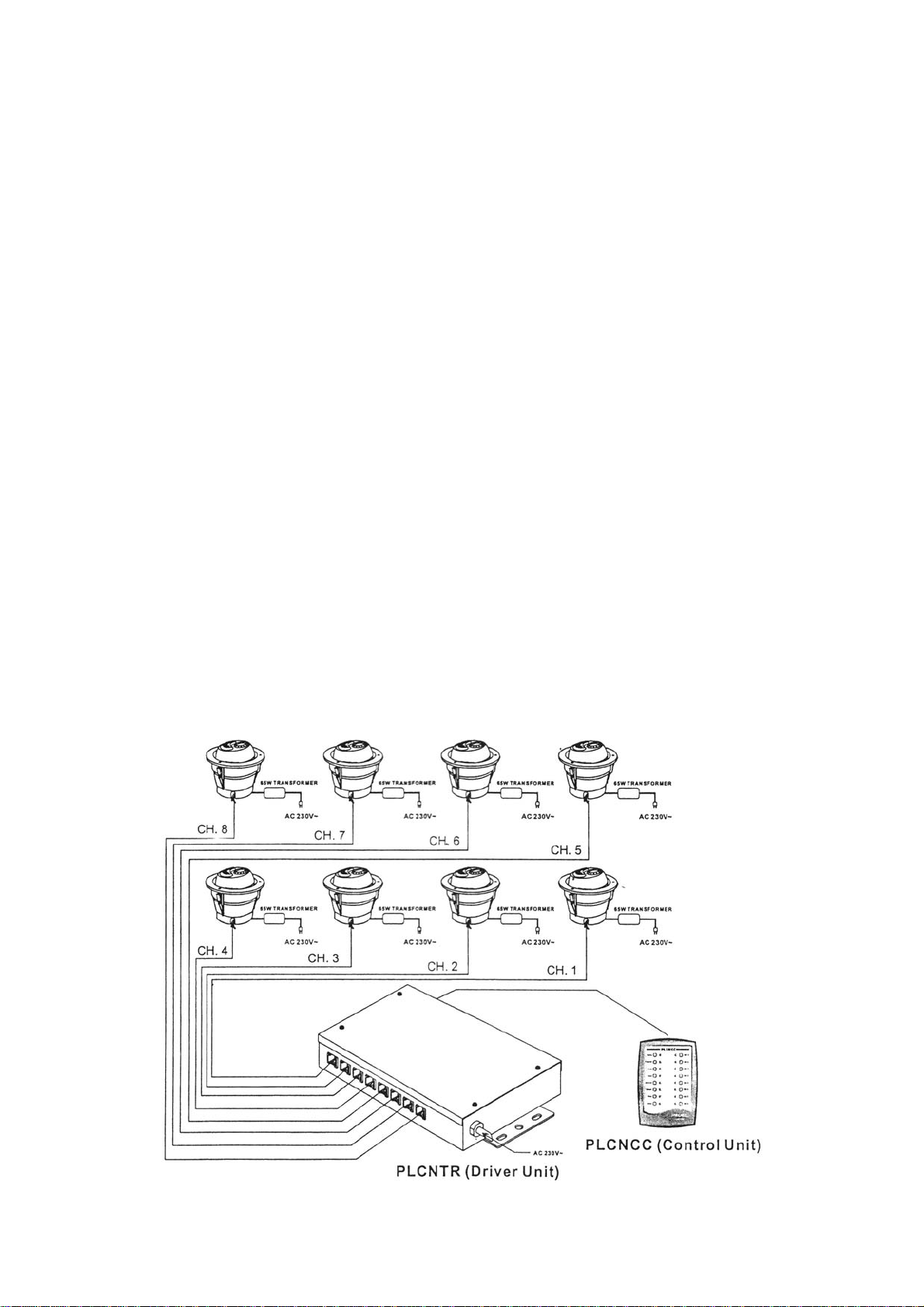
Il TURTLE SPLITTER PLCNTR è l’unità di interfaccia tra faretti Proel PLCCSF e
il controllo Proel PLCNCC. Il PLCNTR ha 8 canali di uscita. Ciascun canale può
controllare fino a 4 faretti, permettendo così di gestire con una sola unità di
interfaccia PLCNTR un massimo di 32 faretti.
CARATTERISTICHE TECNICHE
Alimentazione: AC 230V – 50Hz, 0.5A max
Uscita motore: DC 12V / 0.8A, jack a 6 poli
Presa DMX: Presa XLR tripolare / jack a 4 poli
Fusibile: F0.5A 250V 5x20mm
Dimensioni: 210×125×42 mm
Peso: circa 1,4 Kg
ISTRUZIONI GENERALI
INDIRIZZAMENTO DMX
Prima di tutto installare i faretti PLCCSF secondo la disposizione desiderata.
Collegare in un secondo momento l’interfaccia PLCNTR ai faretti tramite il cavo
a 6 vie. L’impianto così strutturato può essere controllato dal TURTLE
CONTROLLER PLCNCC della Proel oppure da una centralina DMX standard.
Collegare il controller / centralina all’interfaccia PLCNTR utilizzando un cavo a 4
vie. Se si adopera una centralina DMX, connetterla all’interfaccia PLCNTR
tramite un cavo DMX. L’indirizzo dell’interfaccia PLCNTR può essere impostato
tramite i dip-switch su un valore compreso tra 1 e 511.
Se si adopera il controller PLCNCC, è possibile avviare allo stesso modo
l’indirizzamento tramite i dip-switch ma questa volta se si imposta un indirizzo
maggiore di 8, l’unità di interfaccia PLCNTR non riconosce il segnale.

4
TABELLA DI INDIRIZZO DMX
Num. Canale
Iniziale Switch su ON
1 1
2 2
3 1,2
4 3
5 1,3
6 2,3
7 1,2,3
8 4
9 1,4
10 2,4
11 1,2,4
12 3,4
13 1,3,4
14 2,3,4
15 1,2,3,4
16 5
… …
511 1,2,3,4,5,6,7,8,9,
IMPOSTAZIONE INDIRIZZO DMX

5
All’accensione dell’impianto, tutti i faretti TURTLE COLOR PLCCSF collegati
avviano l’operazione di reset. Tale operazione richiede circa 12 secondi durante
i quali i TURTLE COLOR si posizionano sull’effetto ad illuminazione bianca.
Terminato il reset, essi tornano alla posizione memorizzata.
APPENDICE: Corrispondenza dei valori di uscita DMX
0 - 42 bianco 140 - 172 blu
43 - 74 ambra 173 - 204 ciano
75 - 107 verde 205 - 252 arancione
108 - 139 rosa 253 effetto rainbow
ATTENZIONE
L’unità deve essere collegata a terra.
Onde evitare principi di incendio o rischi di scariche elettriche, non esporre
l’apparecchio in zone eccessivamente umide e tenerlo lontano da liquidi.
In caso di sostituzione del fusibile, utilizzarne uno con le stesse caratteristiche.
Non tentare di riparare ma affidarsi a personale qualificato.
ESEMPIO DI CONFIGURAZIONE DI UN IMPIANTO

6
PRODUCT DESCRIPTIONS
PLCNTR is the driver unit of the system. The driver unit has 8 output channels.
Each of the 8 output channels can drive up to 4 PLCCSF units, allowing a
maximum of 32 PLCCSF to be controlled from each PLCNTR driver unit. Please
carefully read this instruction manual for step-by-step setup ad operations.
TECHNICAL SPECIFICATIONS
Power Input: AC 230V – 50 Hz, 0,5A max.
Motor Output: DC 12V / 0,8A, 6 pin telephone jack
DMX socket: 3 pin XLR Neutrik socket / 4 pin telephone jack
Fuse: F0,5A 250V 5x20mm
Dimensions: 210×125×42 mm
Weight: Approx. 1,4 Kg
PRODUCT INSTRUCTION
SETTING DMX ADDRESS
First install the PLCCSF units in the desired location, then connect them to the
driver unit using the 6-way flat cables. The system may be subject to either
PLCNCC (control unit) or any standard DMX controller.
If you are using the control unit, connect it to the driver unit by plugging a 4-way
flat cable into the 4-pin telephone jack. After establishing linkage with the
PLCNCC, you can set the starting address 1-8 using the dip-switches. If you set
an address higher than 8 the driver unit will not respond.
If you are using a DMX controller, connect it to the driver unit using DMX cable.
Now you can set any address within 1-511 when output of the DMX controller is
available.

7
DMX ADDRESS TABLE
Start CH Switch ON
1 1
2 2
3 1,2
4 3
5 1,3
6 2,3
7 1,2,3
8 4
9 1,4
10 2,4
11 1,2,4
12 3,4
13 1,3,4
14 2,3,4
15 1,2,3,4
16 5
… …
511 1,2,3,4,5,6,7,8,9,
DMX ADDRESS SETTING

8
Once you have completed correctly configuration, apply the power on the
system. All PLCCSF units in this system will perform reset function. It may take
about 12 seconds for them to resume white. Subsequently, the PLCCSF units
will move to the previously set position.
APPENDIX: DMX output values
0 - 42 white 140 - 172 blue
43 - 74 amber 173 - 204 cyan
75 - 107 green 205 - 252 orange
108 - 139 pink 253 autoscroll
WARNING
This unit must be earthed
To prevent fire or shock hazard, do not expose this apparatus to rain or moisture
Replace the fuse with the same type
No user serviceable parts inside, do not attempt repairs
Refer to qualified personnel for service.
EXAMPLE OF SYSTEM CONFICURATION

9
Notes:

10

11

PROEL S.p.A.
(World Headquarters – Factory)
Via alla Ruenia 37/43
64027 Sant’Omero (TE) – Italy
Tel. +39 0861 81241
Fax. +39 0861 887862
www.proelgroup.com
Table of contents