Profab FDD- PRO V Operating manual

OPERATING AND MAINTENANCE INSTRUCTION
PROFAB MODEL FDD- PRO V

CD 66
2
2
INDEX
A. INTRODUCTION 4
B. WARRANTY 4
C. DESCRIPTION CAPACITOR DISCHARGE WELDING UNIT 5
1. Identification 5
2. Generality 6
3. Technical data 7
4. Welding control 8
5. Gun: Contact Black 9
D. CONDITIONS OF USE PROVIDED AND NOT PROVIDED 10
1. Intended used 10
2. Unintended used 10
E. PROCEDURE 10
F. COMMISSIONING 11
1. Connection to the electrical power 11
2. Machine adjustment 12
3. Combination of materials 14
4. Cable connecting 14
5. How to get a good weld 14
a. Characteristics of the working surface 14
b. Positioning the pieces 14
c. The gun using 14
6. Operations to avoid 16
G. SECURITY MEASURES 17
1. Safety devices installed on the welding machine 17
2. Verification of safety device 18
H. TROUBLESHOOTING 20
I. MAINTENANCE 20
1. Cleaning inside by professionals 22
2. Routine maintenance 23
3. Extraordinary maintenance and repairs 23
J. EMERGENCY SITUATIONS 24
1. For small fire 24
2. For equipment failure 24
K. TECHNICAL DOCUMENTATION 24
L. RESIDUAL RISKS 25
M. NOISE LEVEL 26
N. PARTS 26
O. INFORMATION ON DEMOLITION 26
P. INDICATIONS FOR UNDERSTANDING THE SAFETY REQUIREMENTS 27
ATTACHMENTS
N. 1 REGISTER OF PERIODICS CHECKS WELDER 28
N. 2 PARTS FOR WELDING CAPACITIVE DISCHARGE 29
N. 3 EXPLODED WELDER WIEW 30
N. 4 CIRCUIT DIAGRAM 31
N. 5 GUN SECTION 32
N. 6 LIST SPECIAL GUN IN CONTACT BLACK 33
CONTACT DETAIL 34

CD 66
3
3
A. Introduction
We want to thank you for your preference with the purchase of a welding
machine CRT Eurosaldature produced entirely in Italy, a guarantee of reliability,
ease of use, durability, with direct assistance and immediate availability of a wide
range of spare parts.
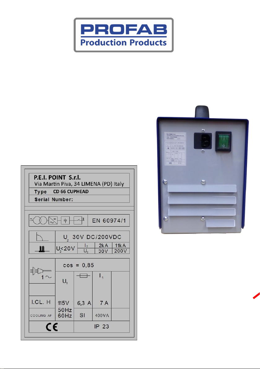
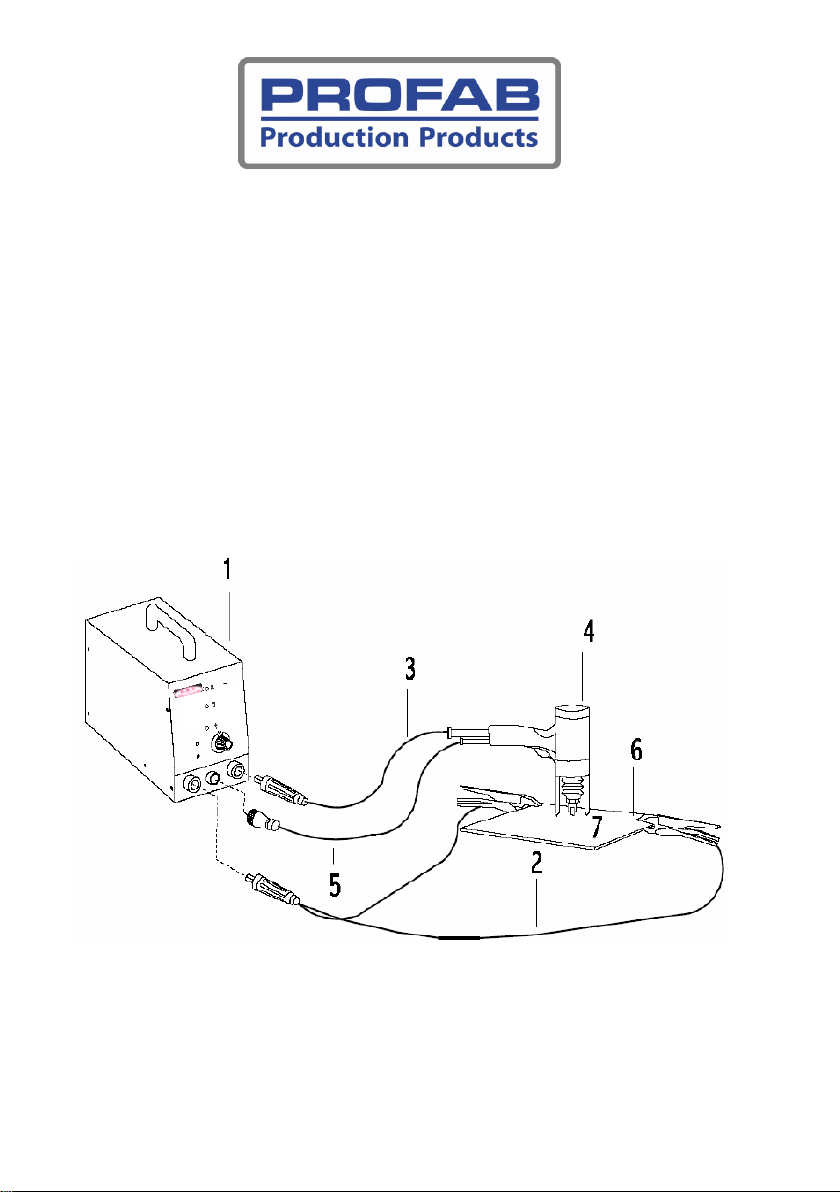
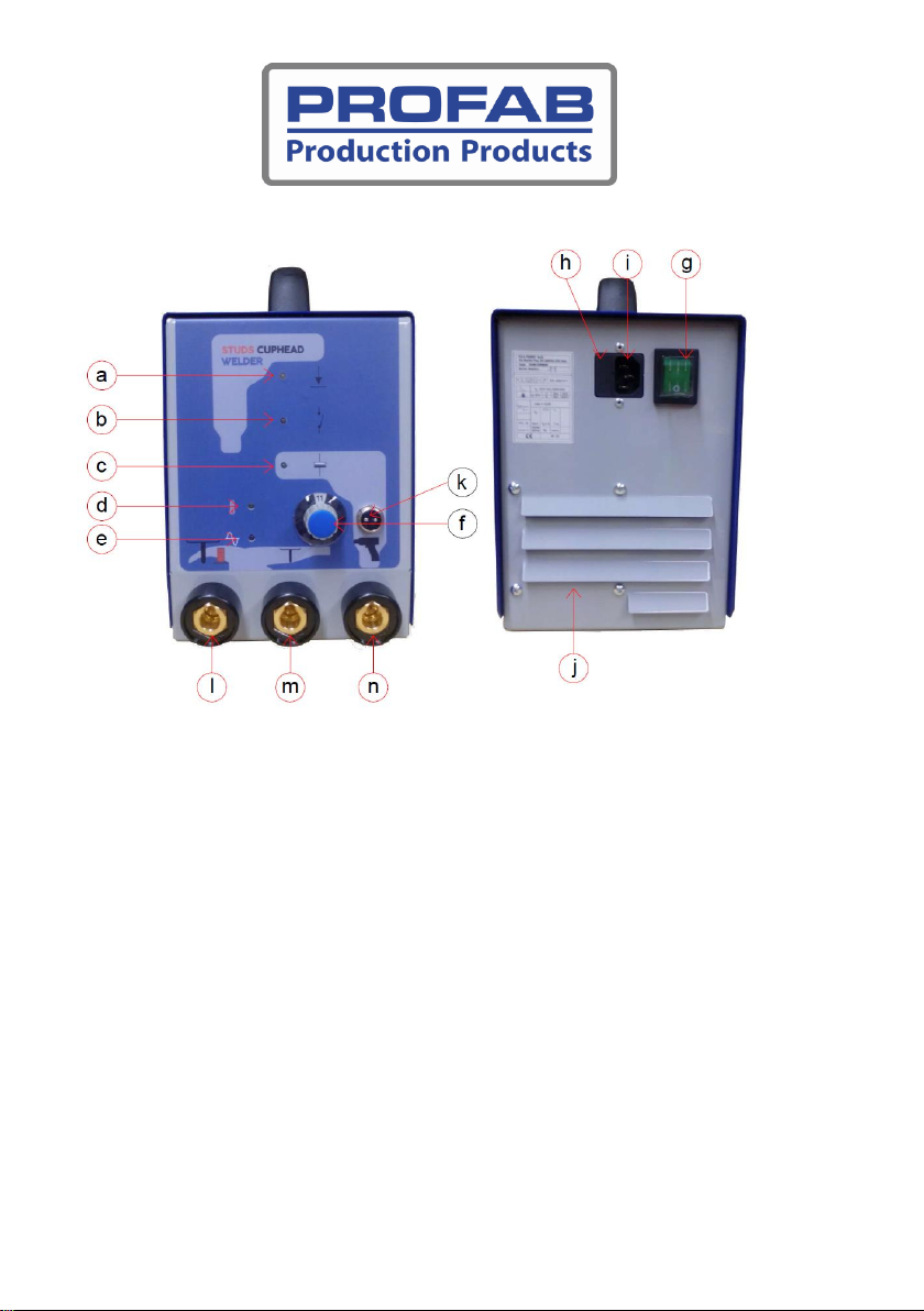
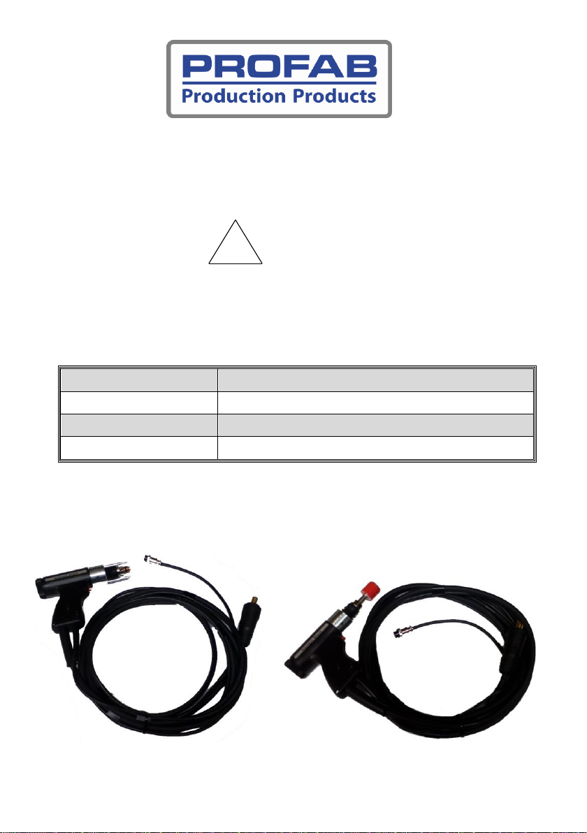
The machine, for the welding capacitor-discharge, provided of special stud
welding gun, is used in various sectors of manufacturing. Such a plant allows the
application of pins and metal inserts of various types.
This manual has been prepared to convey the necessary skills to enable safe
use of the machine. To this end, each user must read it carefully before starting
up the machine, respecting all indications, obligations and prohibitions.
The capacitive discharge welding machine has been designed and built to be
used in the method of welding capacitor-discharge, in combination with the
welding gun of the contact type, supplied.
Within the limits and conditions set out by the following manual, a different
use is contrary to the purpose for which the machine was built.
B. Warranty
Upon delivery of the welder capacitor discharge, the purchaser must verify the
absence of anomalies if any, to be reported within the statutory time limits.
The guarantee, which lasts TWO years from the day of delivery.
It should however be noted that any tampering of any kind, by the user or by
unauthorized personnel will void the warranty, CE marking and the manufacturer's
declaration, raising the manufacturer from any responsibility for any damage to
persons or property caused by such tampering.
The manufacturer is also relieved from liability arising from the following
cases:
•Incorrect maintenance.
•Lack of maintenance on schedule.
•Improper use of welding capacitor discharge.
This manual is provided by CRT EUROSALDATURE srl without any
responsibility. CRT EUROSALDATURE Inc. reserves the right to make this manual
at any time and without notice, changes resulting from typographical errors,
inaccuracies in the content, or improvements of programs and equipment.
Any changes will in any case incorporated into new editions of this manual. In
no event CRT EUROSALDATURE Ltd be liable for any direct, indirect, special,

CD 66
4
4
incidental or consequential, arising from the use or not ability to use the system
or documentation.
Copyright © 2018 C.R.T. EUROSALDATURE srl.
All rights reserved. Printed in Italy.
C. Description welding capacitor discharge
C.1 –Identification
On the welding machine is fixed an
identification plate, on which in addition to the
CE marking shows the general characteristics
of the machine.

CD 66
5
5
C.2 –Generality
With reference to Figure 1, the welding machine must be combined with a gun
for welding so as to constitute a welding system comprising:
(1) capacitor discharge welding unit
(2) ground duble cable
(3) power cord
(4) contact gun
(5) control gun cable
(6) base plate
(7) stud
Fig. 1

CD 66
6
6
C.3 –TECHNICAL DATA
Equipment type
Capacitor discharge welding unit CD 66
CUPHEAD
Diameter pins ferrous
3 ÷ 8 mm
Diameter steel pins - aluminum
3 ÷ 6 mm
Weldable pieces minute
7 ÷ 20
Total capacity
66.000 uF
Energy
1320 Joule
Maximum recharge time
5,0 seconds
Voltage
115 V –50/60 Hz
Power max peak
600 Watt
Contact circuit voltage
15 V
Resistance max allowable contact
30
Charging voltage
30 ÷ 200 VDC
Protection
IP 23
Field working temperatures
0 ÷ 40 °C
Power cord
2 m detachable with plug 10A
Dimensions without handle
16x42x23 cm
Machine weight
14,0 kg
Single ground cable length
5 meters
Gun type
Contact black
Gun cable length.
5 meters

CD 66
7
7
C.4 - WELDING CONTROLS
Fig. 2
a. Yellow LED indicator contact piece.
b. Red LED indicator start command.
c. Green LED indicator took charge of the capacitor.
d. Yellow LED indicator for over temperature protection.
e. Red LED indicator 115 V line.
f. Graduated knob adjustment charge voltage.
g. Lighted bipolar line switch.
h. Storage for two fuses (6,3 A delayed)
i. Socket line cable
j. Ventilation slots.
k. Control cable panel male
l. Ground cable socket for studs and big cuphead
m. Ground cable socket for small cuphead
n. Welding gun socket

CD 66
8
8
C.5- Gun: Contact Black
The welding contact gun is equipped with a magnet for Cuphead use or stud
holder for use with a threaded pin of maximum length 40 mm.
!
IS ABSOLUTELY FORBIDDEN TO MODIFY THE GUN
WITHOUT PRIOR VERIFICATION OF FEASIBILITY BY THE
MANUFACTURER.ANY ACTION CONTRARY TO THIS PROVISION
WILL VOID THE DECLARATION OF CONFORMITY.
Welding gun-type
Contact
Max diameter welded
6 mm Al/Inox - 8 mm Fe
Weight gun with cable
1,9 kg
Cable length
5 m
B.
The gun is equipped with a tripod which has the task of ensuring the
verticality.

CD 66
9
9
D. Conditions of use provided and not provided
D.1 - Intended uses
The capacitor discharge welding machine was built for stud welding.
!
CAUTION
THE CAPACITOR DISCHARGE WELDING MACHINE,WITH
PARTICULAR APPLICATIONS OR MODIFIED,MUST BE SUBJECTED
TO NEW COMPLIANCE VERIFICATION.
D.2 –Not provided
The capacitive discharge welder is not designed to be used at voltages and power
frequencies other than those indicated in the nameplate.
The standard welding gun must be used complete with tripod and spindles
original, there is no use of non-genuine or otherwise of different constitution or
measure.
The welding machine, as supplied, is not required for operation in automatic
cycles of welding.
Any tampering or welding gun will compromise safety.
E. Procedure
The welding process uses the fusion of a small cylindrical appendix, of basic
material, obtained under each pin, caused by the passage of a current of appropriate
intensity and for a suitable and predetermined welding time.
The solder thus obtained, due to the modest energy used not gives rise to
drawbacks of the arc welding or resistance, such as thermal stress or deformation of
the surfaces of the materials.
It will therefore be important that the appendix of the pin is not inserted into
small depressions or punch marks of the base material.
The welding machine is essentially constituted by an electronic circuit which
provides adjustment for the position of electrical capacitors to a voltage proportional
to the diameter of the pins to be welded.
A power module will, on operator command, to the provision of the discharge
current of the capacitor. On complex pin-piece basis, it will be achieved so the fusion
of the appendix of the pin and, for the slight pressure carried out on the same, the
welding, due to the solidification of the material brought to fusion.

CD 66
1
10
0
F. Commissioning
F.1- Connection to the electrical power
!
NOTICE
BEFORE POWERING THE WELDING MACHINE,MAKE SURE THAT
THE ELECTRICAL POWER SUPPLY SYSTEM,HAS BEEN
PERFORMED IN A WORKMANLIKE MANNER;THAT IS EQUIPPED
WITH A PROTECTIVE CONDUCTOR (PE YELLOW -GREEN)AND
DIFFERENTIAL SWITCH.
Do not use many extension cords and adapters.
Highlight with sign of danger wrappers containing live parts.
!
CAUTION
VOLTAGE OPERATING SYSTEM IS 115 V, 50/60 HZ,SINGLE
PHASE
!
CAUTION
BEFORE CONNECTING THE MACHINE TO THE POWER
SUPPLY IS NECESSARY TO ENSURE THAT THE
ELECTRICAL SYSTEM HAS BEEN PERFORMED ARULE OF
ART, AND IS EQUIPPED CIRCUIT PROTECTION ELECTRIC
(PE YELLOW GREEN) AND THE LINE IS PROTECTED BY A
DIFFERENTIAL SWITCH
•Connect the welding gun two poles control plug in the connector panel on
the front of the welding tightening the retaining ring.
•Insert the ground plug in the bush and tighten moderately turning it
clockwise, attach the clamps placed at the other end of the cable to the
base piece.

CD 66
1
11
1
•Connect the plug, marked with the symbol of the gun plug power,
connected to the gun itself and moderately tighten clockwise.
•Connect the machine to the 115 V line , making sure that the main switch
of the same is in the off position (0).
•Before turning on the machine, rotate fully counterclockwise adjustment
potentiometer.
•Switch on the system by bringing the power switch in the on position (on),
to ensure that the LEDs meet the following conditions:
yellow LED alarm overheating
Off
red LED 115 V line
On
green LED OK
On with charged capacitors.
yellow LED contact
Off
red LED button
Off
F.2 –Cable connecting
For smaller diameter Cuphead use, connect the ground cable in
the center bottom plug. For higher diameter Cuphead use, and also
threaded stud, connect the ground cable in the left bottom plug.
F.3 - Machine adjustment
Looking at the tables (tab. A-b) of combinations of voltage-diameter, adjust
accordingly the potentiometer on the values obtained from the table itself.
These values are indicative and will, from time to time, refined from practical
experience, in order to obtain good welds with respect to the processing in use.
A) Tab. A –TABLE OF MATERIALS FERROUS (VOLTAGE REGULATION)
stud
Diameter
Fe 360 / 4.8
Galvanized steel sheet
/ 4.8
Alloy steel / 1.4301
3 mm
3
3
4
4 mm
5
4
5
5 mm
6
5
6
6 mm
8
8
8
8 mm
10
10
-

CD 66
1
12
2
B) TAB. B –TABLE OF MATERIALS NON-FERROUS (VOLTAGE
REGULATION)
Pins
Diameter
Cu Zn 37 / Cu Zn 37
Al Mg / Al Mg3
Al 99, 5 / Al 99,5
3 mm
2
3
3
4 mm
4
4
4
5 mm
5
7
6 mm
7
9
8 mm
9
-
The values in the table are indicative. Appropriate adjustments will be made case
by case
!
NOTICE
IN NO EVENT SHALL THE MANUFACTURER OF THE WELDER IS
RESPONSIBLE FOR ANY DAMAGE CAUSED TO PEOPLE OR TO THE
INEFFICIENCY OF THE WELDS MADE.
!
CAUTION
THE GUARANTEE OF AN EFFECTIVE WELDING WHICH
ENSURES THE MECHANICAL RESISTANCE VALUES
DESIRED, IT SHOULD ALWAYS BE VERIFIED BY
DESTRUCTIVE MECHANICAL TESTS
•Perform, then, a welding and verify visually and mechanically applying a
vertical traction on the pin welded.
•The welding is developed through three phases summarized:
1. Positioning of the gun with pin inserted;
2. Start capacitive discharge, the current flow trough stud.
3. Diving stud in the melt.

CD 66
1
13
3
F.4 –Combination of materials (stud)
As indicated in the table c is possible to weld together materials having similar
compositions. The types of pairings most common are:
C) TAB. C –MATERIALS COMBINATION
F.5 –How to get a good weld
In order to get a good weld is essential that you meet some basic
requirements related to the work surface, positioning the pieces, provision of the
ground plane, use of the gun.
F.5 –a –Characterictis of the working surface
The final quality of a weld is strongly influenced by the characteristics of the work
surface.
The work surface must be:
• Unpainted
• Free of oils or chemicals
• Smooth or with limited roughness (less than or equal to approx. 70 x 10-6 m )
Ferrous materials
Ferrous materials
Type stainless steels
Ferrous materials

CD 66
1
14
4
F.5 - b -Positioning of the pieces
The workpieces must be placed on a surface and not deformable solid, to
ensure the perpendicularity of the gun and of welded pins, while also avoiding the
deformation of the workpiece, especially if of limited thickness.
F.5 - c - The welding gun used
You must first choose the appropriate PIN holding spindle to diameter welding
stud in planned measures and adjust the projection of about 2 mm from the copper
stud holder by adjusting the end stop screw which should then be blocked by the lock
nut.
You should then inserting the stud holder into the gun adjusted by tightening the nut
by means of socket wrench, while checking the tightness and stability of the
supporting feet.
Carrying, therefore, the pin into the exact point of work on the gun by applying a
vertical pressure and compressing, as well, the contrast spring until it rests stably
support feet on the workpiece.
Prestressing of the spring can be varied by turning the ring placed on the gun and
indicated by the index on the left (clockwise increases); thus it is varied the speed of
immersion of the pin into the molten bath welding. Adjust to get the best result.
Retaining the position thus achieved gun press starting the welding cycle and then
remove from the pin welded so absolutely vertical, without lateral bending that
would cause damage to the spindle.
Be sure the internal surface of copper stud holder are in best condition, for haven’t
stud damage.
!
CAUTION
ACHUCK WORN INTERNALLY FROM USE TOO,
COULD RESULT IN ABOW OF POWER BETWEEN SE
'ARMED AND PIN, DISPERSING ENERGY WELDING .

CD 66
1
15
5
F
F.
.6
6
-
-
Operations to avoid
GETTING TO AVOID
CONSEQUENCES
Use of the system without wearing
fireproof clothing, protective glasses,
insulated gloves and protective earplugs
-
Damage operator
Use of the system in humid
-
Damage to plant solder
- Hazardous electrical shock to the
operator
Operate on structures simultaneously
with other welding devices, especially if
high-frequency (inverter)
-
Dangerous interference
Connect the ground clamps away from
the place of welding
-
Damage to structures and systems
Operate in the vicinity of the plant with
electric grinders and grinding plant
-
Damage caused by the aspiration of
ferrous scrap
Make any changes to the stud holder or
the gun in general
-
Hazardous electrical shock to the
operator
Avoid welding in the vicinity and
especially through flammable
materials
-Fire

CD 66
1
16
6
G. Security measures
G.1 - Safety devices installed on the welding machine
The welding machine is equipped with a circuit for measuring the contact
resistance, which enables the flow of the welding current only when the value of
resistance is such as to reinforce a good contact between the pin to be welded, and
ground plate. In this way, during the phases of insertion of the pin in the gun or
manipulation of the same, away from the surface intended to receive the stud
welding and connected to the other pole of the welding circuit, the exposed metal
parts of the gun, are not in dangerous voltage.
During the step of positioning of the pin (pin contact), there is circulation of low
current is not dangerous for humans. In any case, always use suitable clothing to
protect themselves from the danger of electrocution, especially if in the presence of
moisture.
The moment in wich the button is pressed to start the welding cycle, the
resistance of the welding circuit is cheked, if this is lower than that provided by the
manufacturer is enabled by the passage of the arc current, which causes the welding
of the stud.
Are denied access to the internal parts of the welding leads, with power plug
inserted.
In case of use the welding machine is set in place appropriate gloves required PPE
for 'electrical insulation', DPI ear protection (earmuffs or earplugs) and DPI eye
(glasses).
MAKE SURE:
The electrical power supply of the welding machine equipped with differential
switch with high sensitivity (
=
N
I
30 mA), coordinated with an efficient earthing
system, protection against indirect contact.
On welding unit are affixed to the necessary warning information, as specified in
the following diagram.

CD 66
1
17
7
G.2 –Verification of safety
device
!
NOTICE
VERY IMPORTANT TO MAKE THE CHECKS PROVIDED
MANUAL CIRCUIT PROTECTION TO ENSURE THE
SECURITY LEVEL INTENDED BY THE MANUFACTURER.
And therefore essential to proceed as follows:
•welding unit is switched off, connect the ground plug and attach the clamps
to a metal base large enough to hold the plate with insulation resistance
test;
•connect the gun power cable;
•absolutely not connect the control cable
•turn on the system and check that:
•the red light is on (115 V line)
•the yellow light of overheating is off;
•the green light of the battery is charged is on;
•the yellow light contact is off
Indication "Caution
High Voltage"
Label CE marking

CD 66
1
18
8
•the red light button is off;
- insert a stud in a stud holder and push the gun on the metal support thus
verifying the yellow LED contact, is on.
- in the next stage to remove the gun and interpose between it and the metal
base plate (P) of insulation test provided, pushing the gun, the yellow LED of
contact must not light, thus verifying the inhibition of the welding unit to weld
with a value resistance just over 27and much less than that can occur for a
careless operator contact.
!
NOTICE
AND MUST WHEN USING THE MACHINE GLOVES TYPE DPI
ELECTRICAL INSULATION.
In case there is the last condition is essential not to use the system immediately
and contact the supplier or the manufacturer.

CD 66
1
19
9
H. Troubleshooting
FAULT
POSSIBLE CAUSES
REMEDIES
No welding takes
place
Button defective
Check the function through
the respective lamp
-Power cable interrupted
-Control cable interrupted
-Ground cable interrupted
Check the contact function of
the machine via the
respective lamp
Welding machine fails
Contact Technical Service
The welding machine
is in thermal
protection
Fan blocked by the presence
of foreign bodies
Removal of foreign bodies
Contact Technical Service
Welds uneven
Worn stud holder
Replace stud holder
Pliers ground loose or poorly
arranged
Check and replace
Detachment of studs
Insufficient spring pressure
Increase pressure
Loose cables
Cables clamping
Insufficient charging voltage
Adjust according to table
Vertical gun not
Check the height of the feet
Dirty surfaces
Cleaning of surfaces
I. Maintenance
!
CAUTION:
BEFORE ANY MAINTENANCE MAKE SURE THAT THE
POWER CORD, IS OFF.

CD 66
2
20
0
!
CAUTION
THE CAPACITIVE DISCHARGE WELDING UNIT, IS
EQUIPPED WITH A SYSTEM FOR AUTOMATIC DISCHARGE
OF THE CAPACITORS, WHEN POWER IS CUT.
WHEN THE WRAPPER PROTECTION, (TOP COVER)
ENSURE THAT THE RED LED ON THE ELECTRONIC BOARD
IS POWERED OFF, SECURITY DOWNLOAD OCCURRED.
Disconnect power
This manual suits for next models
1
Table of contents