PROFESSIONAL HYDRAULIC JACKS 51605 User manual

Failure to read these warnings may result in loss of load, damage to the jack and/or jack failure resulting
in personal injury or property damage.
This is a lifting device ONLY. Do not move or dolly vehicle while on the jack.
Position this jack to ONLY lift on the areas of the vehicle as specified by the vehicle manufacturer.
After lifting the vehicle, ALWAYS support the load with appropriately rated vehicle support stands
BEFORE working on the vehicle.
Do not overload this jack beyond its rated capacity. Overloading can cause damage to or failure of the
jack.
This jack is designed ONLY for use on hard level surfaces capable of sustaining the load. Use on
other than hard level surfaces can result in jack instability and possible loss of load.
Center load on jack saddle BEFORE lifting vehicle. Off-center loads and loads lifted when the jack is
not level can cause loss of load or damage to the jack.
Study, understand and follow all instructions in this manual BEFORE operating the jack.
SAVE THESE INSTRUCTIONS.
It is important that you read the material to become familiar with the unit BEFORE you begin assembly.
IMPORTANT SAFETY INSTRUCTIONS!
READ ALL INSTRUCTIONS BEFORE USING THIS PRODUCT
Warning
The warnings, cautions, and instructions discussed in this instruction manual cannot cover all possible
conditions and situations that may occur. It must be understood by the operator that COMMON SENSE
AND CAUTION ARE FACTORS TO BE SUPPLIED BY THE OPERATOR.
The Operator
1.Do not operate the product if under the influence of alcohol or drugs. Read warning labels on
prescriptions to determine if your judgment reflexes might be impaired.
2.Do not wear loose clothing or jewelry as they can be caught in moving parts.
3.Protective gloves and non-skid footwear is recommended.
4.Wear restrictive hair covering to contain long hair.
5.Use eye and ear protection. Always wear ANSI approved impact safety goggles.
6.Maintain proper footing and balance at all times.
7.Avoid unintentional starting. Do not carry any tool with your finder on the trigger, whether it is connected
to the compressor or not.
Work Area
TO AVOID RISK OF PERSONAL INJURY, EQUIPMENT DAMAGE, FIRE AND SHOCK, MAKE SURE
YOUR WORK AREA IS:
Free of damp, wet or rainy conditions.
Free of flammable gasses of liquids.
Free of children (never let them handle tools or machinery).
Well-lit.
Clean and uncluttered.
Well-ventilated.

Assembly
Your bumper jack will require no assembly.
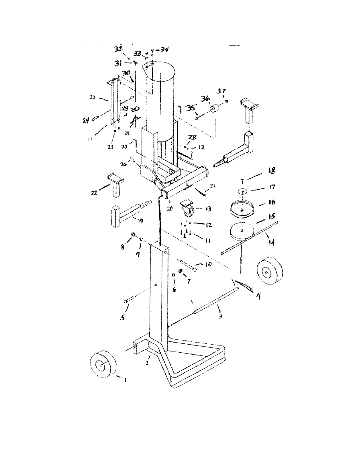
It is important that you read the entire manual to become familiar with the unit BEFORE you use it. Be
sure that you have all parts described in the Parts List.
Air Connection
Step 1 - You will need a Union fitting (sold separately) before you can connect your bumper jack to an air
compressor. Attach the Union fitting to the air inlet and tighten the fitting.
Step 2 - Attach and air coupler (sold separately) to the Union fitting if desired. This is a useful accessory
as it allows quick-coupling action when using a variety of tools with the same air compressor. Your
bumper jack is now ready to use.
Before Operating
Before operating your bumper jack, check for damaged parts. You should also do the following:
DO NOT exceed the tools maximum capacity of 5 Tons. Do not exceed maximum PSI (200psi)
Check for damaged parts. Before using any tool, any part that appears damaged should be carefully
checked to determine that it would operate properly and perform its intended function.
Operation
Never force the tool or attachment to do the work of a larger industrial tool. It is designed to do the job
better and more safely at the rate for which it was intended.
Setup: Frequent, but not excessive, lubrication is required for best performance. Oil added through the
airline connection will lubricate internal parts. An automatic airline oiler is recommended but oil may be
added manually before every operation or after about one (1) hour of continuous use. Only a few drops of
oil at a time are necessary. Too much oil will collect inside of the tool and be blown out during the
exhaust cycle. Use only pneumatic tool oil. Do not use detergent oil or additives as these lubricants will
cause accelerated wear to the seals in the tool.
Dirt and water in the air supply are major causes of pneumatic tool wear. Use a filter/oiler for better
performance and longer life of the tool. The filter must have adequate flow capacity for the specific
application. Consult the manufacturer’s instructions for proper maintenance of your filter.
Using the Bumper Jack
The bumper jack should be tested often and whenever it is suspected of working improperly. Do not use if
working improperly.
Step 1 - Position the vehicle you are working with on a hard, level surface. Make certain the parking
brakes are “ON”, when lifting trailers; lower any landing gear for support.
Step 2 - Position the lift saddle under the frame at locations recommended by the vehicle manufacturer.
Step - Connect the air compressor hose to the air inlet. Turn on the compressor. Turn the valve to the
direction marked “UP” to raise the lift saddle so that it makes contact with the frame of the vehicle. Make
certain that the load is centered with the lift saddle and positioned to prevent load slippage.
Step 4 - Continue to lift the load to a height needed. Making certain that the vehicle stands are in place
under the load, lower the jack by pushing up the lock handle and turning the valve to the direction marked
“DOWN”.
WARNING: Before doing any work, make certain that the load and stands are stable.


Parts List
Item No Desc iption Pa t No Quantity
1 Big wheel 161001 2
2 Base 161002 1
Major Axis 16100 1
4 Split pin 5 x 0 161004 2
5 Bolt M27 x 1 0 161005 1
6 Spring washer 27 161006 1
7 Nut M 27 161007 1
8 Nut M 16 161008 1
9 Spring washer 16 161009 1
10 Bolt M 16 x 220 161010 1
11 Bolt M 8 x 16 161011 6
12 Spring washer 16 161012 5
1 Small wheel 16101 1
14 Guiding wheel 161014 1
15 Piston 161015 1
16 Seal ring 161016 1
17 Washer 161017 1
18 Bolt M 12 x 25 161018 1
19 Adaptable arm 161019 2
20 Frame 161020 1
21 Bolt M 8 x 100 161021 1
22 Saddle 161022 2
2 Nut M 8 16102
24 Handle shell 161024 2
25 Cover 161025 1
26 Handle shell 161026 1
27 Bent pin 161027 2
28 Inverting valve 161028 1
29 Fixed block 161029 1
0 Connecting pipe 1610 0 1
1 Joint 1610 1 1
2 Blocking head 1610 2 1
Spring washer 10 1610 2
4 Nut M 10 1610 4 2
5 Bolt M 24 x 120 1610 5 1
6 Rolls 1610 6 1
7 Nut M 24 1610 7 1
Table of contents