Professor GPM500 User manual

USER’S GUIDE -
SMART GPS TRACKER
Model: GPM500 & GPM500a-D
Main Functions:
1) As a basic positioning tracking device
2) Power shut-down / break off petrol oil through Cloud computing system.
3) Monitoring from platform - When power shut down successfully or not may
notice from monitoring platform in the control center.
4) Alert signal – Whenever the wire of device being cut, the device itself may
transmit this to the control centre and you can see the signal alert on the
platform.
5) Setting - The device is set for 60~999second for every step of setting of
function when not continue to send command /setting then will
automatically stop(enter to sleeping mode)
6) Smart upload -Automatically adjustment for flow of loading, if the car is
moving very fast, then will upload fast .If the car is moving slowly then will
be upload slowly. This is to control the flow /density of uploading for the
purpose of money saving because in many countries the bill of sim-card will
cost very expensive whenever if density of uploading is high. .
7) Small and easy to hide - After installation , if you don’t want anyone else
realize that you have a small device installed for detection then you can
hide it with off the LED light.
8) Counting mileage accurately.

I. Specification:
Power:
1. Power range:9-40vDC
2. Power consumption : 20mA (12VDC):10mA(24VDC)
3. Standby-power : 1mA(12VDC):05mA(24VDC)
GSM:
1. GSM Frequency: 900/1800Mhz (For Dual band)
850/900/1800/1900Mhz (For Quad band)
2. GPRS: TCP/ IP
GPS:
Acquisition Rate:
1. Col start: 42 s(Typical)
2. Hot start: 1 s(Typical)
3. Accuracy Position: 10 m, 2D RMS
Environmental Characteristic:
1. Working Temperature: -30℃~+70℃
Dimension:
95(L) x 45(L) x 16(H)mm
II. Product picture:
GPS signal -- > < -- Sim card
GSM signal -- > *
metal CHIP side should be on top
Power for battery -- >
*Red LED light = no battery
*LED light off = full battery
III. LED Light:
1. Blue LED light (GPS signal)

Signal Description
Flash Searching GPS
Light on
continuously
GPS - receiving under normal status
No Flash GPS under searching status/
standby mode
2. Green LED light (GSM signal)
Signal Description
Flash quickly
GSM sending data
Flash slowly Not connect to GSM/
Searching GSM
Light on
continuously
GPRS connect successfully/
under standby mode
No Flash Under sleeping mode
3. Red LED light (For battery power)
Signal Description
Light on
continuously
Charging Battery
No Flash Battery finished charging
IV. Installation Method
1. GSM SIM card ,should be insert to device and make sure the GPRS is
activate. If your SIM card required enter SIM PIN, please refer to your
hand-phone user’s guide to off the SIM PIN function.
2. Tracker will automatically on whenever the SIM card insert and the GPS
Tracker will start to activate.(Noted: sometimes will not activate if it is no
battery. If this happened please charge the GPS Tracker)
3. To activate the Tracker, please place the side with “This side up” on top. If
the Tracker Blue LED light (GPS) never link will directly enter to sleeping mode.
Need to shack the Tracker until Blue light on steady (This mean successfully
link).
4. When install the tracker, suggest in the open space area, GPS signal is
stronger will help for better and stable GPS signal receive.(Installation: avoid
install in raining or wet area .
5. If Tracker install in covert suggest that:
A Avoid install to metal material of vehicle, this will influence GPS
signal receive.
B Avoid install near to the parking sensors/distance control device/ car
alarm and any other which is easily influence the GPS.
*The tinted window film may easily influence and reduce the GPS receive signal.
6. If GPS abnormal/not receiving GPS, suggest change a new place to install
the Tracker device.
V. Wire accessories
:
1. Red wire, connect to car battery (+),
2. Black wire, connect to car battery ( - )
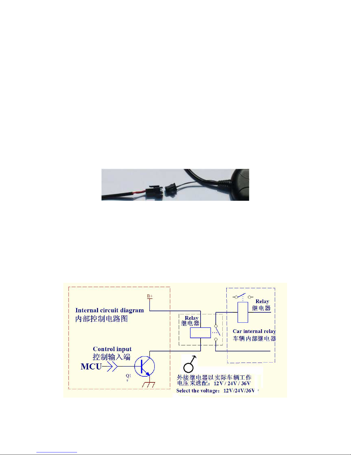
3. Installation for function: Break off petrol oil and power shutdown through
Cloud computing system:
appearance figure
A) Tracker remote control break oil//engine start - the output
relay coil electric /current should be under 1A.
B) After power connection, continue with setting for
parameter.( Please refer to your parameter setting document).
C) The output relay contact point should connect to serial in for
car engine start/oil pump of relay coil.
Block Diagram.

VI .Tracker-Troubleshooting
If monitoring platform shows the vehicle is not active /on line:
1. Please check and make sure the Tracker LED light is in normal status
( Blue /Green LED lights continuously on ) .
2. To check the status you may call from the hand-phone to the Tracker. From
the below, you can check and make sure the status:
A) If cannot reach the line, this mean the Tracker is out of the GSM
service area/ SIM card is not insert properly or you are in
underground/basement. Please drive the car to open space area
for setting.
B) First time setting, need about few minutes. Please make sure on
top the Tracker is no metal material cover to it.
C) After power on for a while, 3 LED lights are off (no signal) then will
be enter to the sleeping mode. .
This manual suits for next models
1
Table of contents
Other Professor GPS manuals


