Profibus PROFIBUS DPV0 User manual

PROFIBUS DPV0
Manual /Users Guide
Gateways & Encoders
Part No 740590-01, Doc. No 740590 Ver. 01

PROFIBUS USER MANUAL Leine & Linde AB
Part Id: 740590-01 2
Document Id: 740590 Ver. 01
Publication date: 2010-06-01
Content
List of tables...........................................................................................................................3
List of pictures .......................................................................................................................4
1 General information...........................................................................................................5
1.1 PROFIBUS GATEWAY.................................................................................................................... 5
1.2 ABSOLUTE ENCODERS ..................................................................................................................... 5
1.3 PROFIBUS TECHNOLOGY............................................................................................................... 5
1.4 ABOUT LEINE &LINDE AB .............................................................................................................5
1.4.1 TECHNICAL AND COMMERCIAL SUPPORT ......................................................................................6
1.5 REFERENCES....................................................................................................................................6
1.5.1 ABBREVIATIONS ...........................................................................................................................6
2 Gateway Installation ..........................................................................................................7
2.1 SETTINGS INSIDE THE GATEWAY......................................................................................................7
2.1.1 NODE ADDRESS ............................................................................................................................7
2.1.2 BUS TERMINATION........................................................................................................................8
2.2.1 POWER SUPPLY .............................................................................................................................9
2.2.1 BUS LINES.................................................................................................................................. 10
2.3 SHIELDING PHILOSOPHY ................................................................................................................11
2.4 GSD-FILES ....................................................................................................................................11
2.5 LED INDICATION ...........................................................................................................................12
3 RSA/RHA 6X8, Encoder Installation ................................................................................13
3.1 SETTINGS INSIDE THE ENCODER..................................................................................................... 13
3.1.1 NODE ADDRESS ..........................................................................................................................13
3.1.2 BUS TERMINATION......................................................................................................................13
3.2 CONNECTING THE ENCODER ..........................................................................................................14
3.2.1 POWER SUPPLY ...........................................................................................................................14
3.2.1 BUS LINES.................................................................................................................................. 15
3.3 SHIELDING PHILOSOPHY ................................................................................................................15
3.4 GSD-FILES ....................................................................................................................................16
3.5 LED INDICATION ...........................................................................................................................17
4 Profile overview ................................................................................................................18
4.1 DPV0 ENCODER CLASSES ..............................................................................................................19
5 Encoder and Gateway functionality, DPV0 ....................................................................20
5.1 BASIC FUNCTIONALITY ..................................................................................................................20
5.2 PROFIBUS DATA TRANSFER PRINCIPLE........................................................................................ 20
5.2.1 DURING CONFIGURATION (DDLM_CHK_CFG MODE)................................................................ 20
5.2.2 DURING PARAMETERIZATION (DDLM_SET_PRM MODE)........................................................... 20
5.2.3 NORMAL OPERATION (DDLM_DATA-EXCHANGE MODE) ..........................................................20
5.3 CONFIGURATION,DPV0................................................................................................................20
5.4 PARAMETERIZATION,DPV0..........................................................................................................21
5.4.1 CODE SEQUENCE.........................................................................................................................21
5.4.2 CLASS 2FUNCTIONALITY............................................................................................................ 22
5.4.3 COMMISSIONING DIAGNOSTICS...................................................................................................22
5.4.4 SCALING FUNCTION CONTROL .................................................................................................... 22
5.4.5 MEASURING UNITS PER REVOLUTION..........................................................................................23
5.4.6 TOTAL MEASURING RANGE (UNITS) ............................................................................................ 24
5.4.7 VELOCITY CONTROL ...................................................................................................................26
5.4.8 VELOCITY CALCULATION ........................................................................................................... 26
5.5 DATA TRANSFER IN NORMAL OPERATION (DDLM_DATA_EXCHANGE)........................................27
5.5.1 DATA EXCHANGE MODE ............................................................................................................. 27
5.5.2 PRESET FUNCTION ...................................................................................................................... 28
5.6 DIAGNOSTICS ................................................................................................................................29

PROFIBUS USER MANUAL Leine & Linde AB
Part Id: 740590-01 3
Document Id: 740590 Ver. 01
Publication date: 2010-06-01
5.6.1 DIAGNOSTIC HEADER .................................................................................................................29
5.6.2 ALARMS .....................................................................................................................................30
5.6.3 OPERATING STATUS ...................................................................................................................30
5.6.4 ENCODER TYPE ........................................................................................................................... 31
5.6.5 SINGLETURN RESOLUTION OR MEASURING STEP .........................................................................32
5.6.6 NUMBER OF DISTINGUISHABLE REVOLUTIONS ........................................................................... 32
5.6.7 ADDITIONAL ALARMS ................................................................................................................32
5.6.8 SUPPORTED ALARMS ..................................................................................................................33
5.6.9 WARNINGS .................................................................................................................................33
5.6.10 SUPPORTED WARNINGS ............................................................................................................34
5.6.11 PROFILE VERSION..................................................................................................................... 35
5.6.12 SOFTWARE VERSION ................................................................................................................35
5.6.13 OPERATING TIME......................................................................................................................35
5.6.14 OFFSET VALUE .........................................................................................................................36
5.6.15 OFFSET VALUE OF THE ENCODER MANUFACTURER ................................................................. 36
5.6.16 SCALING PARAMETERS SETTINGS ............................................................................................ 36
5.6.17 ENCODER SERIAL NUMBER ......................................................................................................37
6 Encoder commissioning example, DPV0 ........................................................................38
Appendix A History .............................................................................................................42
List of tables
Table 1 Terminating switch settings .................................................................................... 8
Table 2 Pinning M12 power supply connector..................................................................... 9
Table 3 Pinning M12 bus in/out – lines.............................................................................. 10
Table 4 Available GSD file for DPV0 gateway ................................................................... 11
Table 5 LED indication.......................................................................................................... 12
Table 6 Terminating switch settings .................................................................................. 14
Table 7 Pinning M12 power supply ..................................................................................... 14
Table 8 Pinning M12 bus in/out – lines............................................................................... 15
Table 9 Available GSD file for DPV0 encoders................................................................... 16
Table 10 LED indication........................................................................................................ 17
Table 11 Operating parameters in DPV0 ............................................................................ 21
Table 12 Octet 9, Parameter definition............................................................................... 21
Table 13 Singleturn scaling parameter format ................................................................. 23
Table 14 Multiturn scaling parameter format................................................................... 23
Table 15 Octet 39 Velocity Control...................................................................................... 26
Table 16 Data exchange 32-bits .......................................................................................... 27
Table 17 Data exchange 16-bits .......................................................................................... 27
Table 18 Preset value, 32-bit format ................................................................................... 28
Table 19 Preset value, 16-bit format ................................................................................... 28
Table 20 Diagnostics message, DPV0.................................................................................. 29
Table 21 Diagnostic header.................................................................................................. 30
Table 22 Alarms .................................................................................................................... 30
Table 23 Operating status .................................................................................................... 31
Table 24 Diagnostics, encoder type .................................................................................... 31
Table 25 Diagnostics, singleturn resolution ...................................................................... 32
Table 26 Diagnostics, number of distinguishable revolutions ........................................ 32
Table 27 Diagnostics, additional alarms ............................................................................ 32
Table 28 Diagnostics, supported alarms ............................................................................ 33
Table 29 Diagnostics, warnings........................................................................................... 34
Table 30 Diagnostics, supported warnings ........................................................................ 34
Table 31 Diagnostics, profile version .................................................................................. 35
Table 32 Diagnostics, software version .............................................................................. 35
Table 33 Diagnostics, operating time ................................................................................. 36
Table 34 Diagnostics, offset value....................................................................................... 36
Table 35 Diagnostics, offset value of the encoder manufacturer .................................. 36
Table 36 Diagnostics, scaling parameters setting............................................................. 37

PROFIBUS USER MANUAL Leine & Linde AB
Part Id: 740590-01 4
Document Id: 740590 Ver. 01
Publication date: 2010-06-01
Table 37 Diagnostics, encoder serial number.................................................................... 37
List of pictures
Picture 1 Placement of screws ............................................................................................... 7
Picture 2 PCB-view of a cable gland PROFIBUS gateway .................................................... 8
Picture 3 Orientation of M12 power supply connector....................................................... 9
Picture 4 Terminal connections of power supply cables.................................................... 9
Picture 5 Orientation of M12 bus connectors .................................................................... 10
Picture 6 Terminal connection of bus line cables ............................................................. 10
Picture 7 PCB-view of a cable gland PROFIBUS encoder................................................... 13
Picture 8 Orientation of M12 power supply connector..................................................... 14
Picture 9 Terminal connection of power supply cables ................................................... 14
Picture 10 Orientation of M12 bus connectors .................................................................. 15
Picture 11 Terminal connection of bus line cables ........................................................... 15
Picture 12 Overview encoder profile and related documents.......................................... 18
Picture 13 Basic functionality .............................................................................................. 20
Pictur 14 Cyclic Scaling......................................................................................................... 24
Picture 15 Non-cyclic scaling............................................................................................... 25
Leine & Linde AB claims copyright on this documentation. It is not allowed to modify, extend or to hand
over to a third party and/or copy this documentation without written approval from Leine & Linde AB.
Specifications and content in this document are subject to change without prior notice due to our
continuous strives to improve functionality and performance of our products.

PROFIBUS USER MANUAL Leine & Linde AB
Part Id: 740590-01 5
Document Id: 740590 Ver. 01
Publication date: 2010-06-01
1 General information
This manual describes installation and configuration options of Leine & Linde devices
with PROFIBUS DPV0 interfaces. The PROFIBUS-DP gateway is the solution for
applications with high ambient temperature. Encoders with integral PROFIBUS DP
interface are advantageous if a very compact solution is required.
In view of the certification by PNO (PROFIBUS user organization) all products can be
used in all PROFIBUS DPV0 systems without restrictions. Among other things this
means that all possible baud rates, the complete address range and the device
characteristics are supported according to the PROFIBUS device profile for encoders.
1.1 PROFIBUS Gateway
The advantages of the gateway concept is that it allows the use of small and very
robust EnDat encoders, which make the gateway solution suitable in applications
where very high ambient temperature is a limiting factor. The Gateway works with all
Leine & Linde EnDat encoders with either M12 or M23 (EML) connectors. The
PROFIBUS gateway supports singleturn encoders with up to 31 bit resolution and
multiturn encoders with up to 37 bits resolution with the limitations described in this
manual.
1.2 Absolute encoders
With an absolute encoder each angular position is assigned a coded position value
generated by a code disc equipped with several parallel fine graduations tracks which
are scanned individually. On singleturn encoders, i.e. an encoder producing absolute
positions within one revolution, the absolute position information repeats itself with
every revolution. So called multiturn encoders can also distinguish between
revolutions. The numbers of unique revolutions is determined by the resolution of the
multiturn scanning and repeats itself after the total resolution is reached.
1.3 PROFIBUS technology
PROFIBUS is a powerful and versatile 2-wire non-proprietary open fieldbus standard
defined by several international standards such as EN 50170, IEC 61158 together with
different device profiles. There are 3 different PROFIBUS versions available today, DP,
FMS and PA. Leine & Linde products support the DP version. In addition to
manufacturer-specific functions, the Leine & Linde products described in this manual
supports class 1 and 2 according to the encoder profile 3.062. The encoder device
profile describing encoder functionality and additional information about PROFIBUS
can be ordered from PROFIBUS User Organization, PNO or directly from Leine & Linde
AB.
PROFIBUS User Organization
Haid-und-Nue Straβe 7
D 76131 Karlsruhe
Tel: +49 721 96 58 590
Fax: + 49 721 96 58 589
Web: www.profibus.com
1.4 About Leine & Linde AB
For more than 40 years, the Swedish based company Leine & Linde has concentrated
on one thing – development and manufacturing of advanced encoders that meet the
most rigorous demands a user can place on them. That is why a wide assortment of
incremental and absolute encoders with obvious concentration on robust products
and quality down to the last detail can be offered. Leine & Lindes encoders provide
the utmost in reliability year after year, in working conditions where vibration, dirt,
cold and other harsh environments are common.

PROFIBUS USER MANUAL Leine & Linde AB
Part Id: 740590-01 6
Document Id: 740590 Ver. 01
Publication date: 2010-06-01
Leine & Linde can meet very specific individual demands. The encoders are easily
adopted due to a modular design in the collection exactly to the customer’s needs
with respect to resolution, electrical connections and interfaces, voltage, casings, etc.
That is due to the fact that tomorrow’s technology already is used today in Leine &
Linde products. Leine & Linde concentrate on advanced development of intelligent
encoders with integrated ASICs, new special features and with adaptations to
different fieldbus systems. This enables us to meet the need for increasingly effective
and dependable machines and automation to an even higher degree.
1.4.1 Technical and commercial support
Leine & Linde are represented by subsidiaries in many countries around the world. In
addition to the address listed here, there are many services agencies and distributors
located worldwide ready to reply to commercial enquires or technical support. For
more contact information, please visit our web site or contact Leine & Linde in
Strängnäs, Sweden.
Leine & Linde AB
Olivehällsvägen 8
SE-645 21 Strängnäs, Sweden
web: www.leinelinde.com Fax: +46 152 265 05
1.5 References
PROFIBUS Encoder profile V1.1, Order No. 3.062
1.5.1 Abbreviations
PROFIBUS Process Field Bus
PI PROFIBUS International
PNO PROFIBUS Nutzerorganisation e.V.
(PROFIBUS user organization)
GSD German term "Gerätestammdaten". A GSD is
the device database file, also called “device
datasheet”.
DP Decentral Periphery
Input data Data which the master receives from the
encoder
Output data Data which the encoder receives from the
master.
PDU Protocol Data Unit
DDLM Direct Data Link Mapper, the interface
between PROFIBUS-DP functions and
the encoder software
DDLM_Set_Prm Interface during parameterization
DDLM_Data_Exchange Interface during data exchange (normal
operation)
DDLM_Slave_Diag Interface during diagnostics data transfer
DDLM _Chk_Cfg Interface during configuration

PROFIBUS USER MANUAL Leine & Linde AB
Part Id: 740590-01 7
Document Id: 740590 Ver. 01
Publication date: 2010-06-01
2 Gateway Installation
2.1 Settings inside the gateway
The gateway addressing switches and bus termination must be configured during
commissioning of the device. This is done by removing the back cover, i.e. screwing
off the three screws at the rear of the gateway.
Picture 1 Placement of screws
2.1.1 Node address
The node address of the gateway can be set via three decimal rotary switches located
inside the back cover. The weighting, x100, x10 and x1 are specified on the circuit
card besides the switches. Permissible address range is between 0 and 126 but the
lower addresses 0 to 2 are usually used by the master and not recommended to be
used by the device. Each address used in a PROFIBUS network must be unique and
may not be used by other devices.
The device address is only read and adopted when the gateway power supply is
switched on. A restart of the gateway is therefore required in order to adopt changes
done to the address settings.
Screws to remove the
back cover

PROFIBUS USER MANUAL Leine & Linde AB
Part Id: 740590-01 8
Document Id: 740590 Ver. 01
Publication date: 2010-06-01
Picture 2 PCB-view of a cable gland PROFIBUS gateway
Example: To set the node address to 115, the switch to the left (x100) shall be set to 1,
the switch in the middle(x10) should also be set to 1 and the switch to the right(x1)
shall be set to 5.
2.1.2 Bus termination
In a PROFIBUS net, all devices are connected in a bus structure. Up to 32 devices
(master and/or slaves) can be connected in one segment. When more devices are
needed repeaters should be used to amplify the signals between segments. An active
termination must be added in the beginning and end of each bus segment in order to
ensure error-free operation. In case of the gateway such terminators are integrated
inside the back cover and can be activated via dip switches as shown in picture 2. If
the device is un-powered the A and B lines are internally terminated by a 220Ω
resistor.
Bit 1 Bit 2 Effect
ON ON There is a 220 ohm resistor between bus-A and bus-B line.
ON OFF Not a valid setting.
OFF ON Not a valid setting.
OFF OFF There is no resistor between bus-A and bus-B line.
Table 1 Terminating switch settings
When gateways with M12 connectors are used the termination can also be done using
a terminating resistor plug. The terminating resistor plug is available as an accessory
from Leine & Linde.
Note: When M12 terminating resistor plugs are used, the internal terminating
switch shall not be activated.
Bus termination
switch
(
on/of
f
)
Node address switches
(x100 to the left, x10 in the
middle and x1 to the right)
Screw
terminals

PROFIBUS USER MANUAL Leine & Linde AB
Part Id: 740590-01 9
Document Id: 740590 Ver. 01
Publication date: 2010-06-01
2.2.1 Power supply
The power supply connection of M12 equipped gateways are constituted by a male A-
coded 4 pin M12 connector.
Picture 3 Orientation of M12 power supply connector
Gateways equipped with cable glands are delivered with a dust protection foil from
the factory. The protection foil needs to be removed prior to installing the cables.
Gateways equipped with cable glands should always be equipped with a shielded
power supply cable with conductor area between 0,34 mm2to 1.5 mm2. Permissible
outer cable diameter is ø 6 mm to ø 8 mm for the power supply cable. The power
supply screw terminal is located inside the back cover of the gateway.
In the case were the gateway is the last node in the bus-structure and only the cable
glands for Supply and Bus-in is in use, the Bus out cable gland should be replaced
with a filler plug to ensure proper sealing. The filler plug is available as an accessory
from Leine & Linde.
The +E terminal shall be used to connect +E Volt (9-36Vdc).
The 0V terminal shall be used to connect 0 Volt.
Picture 4 Terminal connections of power supply cables
Note: Tighten all screws in the terminal, even if no cable has been attached.
Note: The two +E terminals are internally connected to each other and the two 0V
terminals are also connected to each other, i.e. it does not matter to which
pair the +E Volt and 0 Volt are connected to.
Power supply M12 version
Function Pin
+E Volt (9-36Vdc) 1
Not connected 2
0 Volt 3
Not connected 4
Table 2
Pinnin
g
M12 power suppl
y
connector
Power supply

PROFIBUS USER MANUAL Leine & Linde AB
Part Id: 740590-01 10
Document Id: 740590 Ver. 01
Publication date: 2010-06-01
2.2.1 BUS lines
The PROFIBUS bus line connections of the M12 equipped devices are constituted by a
male B-coded 5 pin M12 connector (bus in), and a female B-coded 5 pin M12 connector
(bus out).
Picture 5 Orientation of M12 bus connectors
The cable gland gateways shall be equipped with twisted pair shielded cable in
accordance with EN 50170 and PROFIBUS guidelines. The guidelines recommend a
conductor area higher than 0,34 mm2. Permissible outer cable diameter is ø 8 mm to ø
10 mm for the bus lines cables. Located inside the back cover are four screw terminals
containing the required bus line terminals marked A and B. Cable glands not used,
should be replaced with a filler plug to ensure proper sealing. The filler plug is
available as an accessory from Leine & Linde.
The A terminal shall be used to connect the A-line.
The B terminal shall be used to connect the B-line.
Picture 6 Terminal connection of bus line cables
Note: Tighten all screws in the terminal, even if no cable has been attached.
Note: The two A -terminals are internally connected to each other and the two B-
terminals are also internally connected to each other so it does not matter to
which the bus lines are connected to.
Bus in- lines Bus out- lines
Function Pin Function Pin
Not connected
1 VP 1
A 2 A 2
Not connected
3 DGND 3
B 4 B 4
Chassi 5 Chassi 5
Table 3
Pinnin
g
M12 bus in/out
–
lines
Bus in Bus out

PROFIBUS USER MANUAL Leine & Linde AB
Part Id: 740590-01 11
Document Id: 740590 Ver. 01
Publication date: 2010-06-01
2.3 Shielding philosophy
To achieve the highest possible noise immunity and resistance against other EMI
related disturbances the bus and power supply cables shall always be shielded.
The screen should be connected to ground on both ends of the cable. In certain cases
compensation current might flow over the screen. Therefore a potential
compensation wire is recommended.
2.4 GSD-files
PROFIBUS Gateways can be configured and parameterized corresponding to the
requirements of the user. When the system is started, the PROFIBUS devices are set
and configured in DDLM_Set_Prm mode, i.e. the application class set by means of the
GSD file in the configuration tool and the operating parameters are transferred to the
respective slave.
Available GSD files can be downloaded from www.leinelinde.com.
GSD file
Gateway Functionality GSD file
Gateway, DPV0 llpb0680.gsd
(ll__0680.gsd)
Table 4 Available GSD file for DPV0 gateway
Note: GSD file ll__0680 is supported only for compatibility with old Leine & Linde
Profibus gateway, and is not recommended for new customers.
When configuring the gateways two device classes (Class 1 or Class 2) can be selected
as described in chapter 4. Selectable parameters and functionality of the device
depend on the selected encoder class. This data, saved in the PROFIBUS master is
transferred once to the gateway when the system is powered on. If the gateway has
been started with one GSD file and a new GSD file with a different ID-number shall be
used, the gateway needs to be restarted before it can use the new GSD file.
After the configuration and parameter data have been received, the gateway enters
normal operation with cyclic data transfer i.e. "DDLM_Data_Exchange mode".
Installation of GSD-files:
1. Select and save the GSD file for the respective device from our homepage
www.leinelinde.com and then copy the *.gsd file into the respective directory
of the PROFIBUS configuration tool.
2. Select the bitmap file of the respective device and copy the *.bmp file into the
respective directory of the PROFIBUS configuration tool.
3. Update the GSD files (SCAN).

PROFIBUS USER MANUAL Leine & Linde AB
Part Id: 740590-01 12
Document Id: 740590 Ver. 01
Publication date: 2010-06-01
2.5 LED indication
In order to determine the status of the gateway two LEDs are visible on the front of
the gateway. The module LED indicates status of the module itself. The bus LED
indicates the status of the bus. The table below defines the diagnostic messages using
a bicoloured red/green LED for bus and module.
Bicolour
(Bus status)
Bicolour
(Module)
Meaning Cause
Off Off No Power
Red Green No connection to another device
Criterion: no data exchange
- Bus disconnected
- Master not available / switched off
Red
2)
Red
2)
No connection to another device
No connection between EnDat
encoder and PROFIBUS PCB
- No connection to EnDat Encoder at
power up
Blinking
1 )
Green Parameterization or
configuration fault
- Configuration received differs from
the supported configuration.
- Parameter error in the
parameterization.
Green Red
System Failure - Diagnosis exists, slave in data
Exchange mode
- Position error
Green Green Data exchange.
Slave and operation ok.
Table 5 LED indication
1) The blinking frequency is 0.5 Hz. Minimal indication time is 3 sec.
2) Position error is when an alarm occurs in the encoder or if the EnDat encoder
is disconnected from the PROFIBUS interface PCB.

PROFIBUS USER MANUAL Leine & Linde AB
Part Id: 740590-01 13
Document Id: 740590 Ver. 01
Publication date: 2010-06-01
3 RSA/RHA 6X8, Encoder Installation
3.1 Settings inside the encoder
The encoder node address and bus termination must be configured during
commissioning of the device. This is done by removing the back cover, i.e. screwing
off the three screws at the rear of the encoder.
3.1.1 Node address
The node address of the encoder can be set via two decimal rotary switches located
inside the back cover. The weighting, x10 or x1 are specified beside the switches.
Permissible address range is between 0 and 99 but the lower addresses 0 to 2 are
usually used by the master and not recommended to be used by the device. Each
address used in a PROFIBUS network must be unique and may not be used by other
devices.
The device address is only read and adopted when the encoder power supply is
switched on. A restart of the encoder is therefore required in order to adopt changes
done to the address settings.
Picture 7 PCB-view of a cable gland PROFIBUS encoder
Example: If the node address shall be set to 85, the left(x10) switch shall be set to 8
and the right(x1) switch shall be set to 5.
3.1.2 Bus termination
In a PROFIBUS net, all devices are connected in a bus structure. Up to 32 devices
(master and/or slaves) can be connected in one segment. When more devices are
needed repeaters should be used to amplify the signals between segments. An active
termination must be added in the beginning and end of each bus segment in order to
ensure error-free operation. In case of the encoder such terminators are integrated
inside the back cover and can be activated via dip switches as shown in picture 7. If
the device is un-powered the A and B lines are internally terminated by a 220Ω
resistor.
Bus termination
switch (on/off)
Node address switches
(x10 to the left, x1 to the right)
Screw terminal
PROFIBUS USER MANUAL Leine & Linde AB
Part Id: 740590-01 14
Document Id: 740590 Ver. 01
Publication date: 2010-06-01
Bit 1 Bit 2 Effect
ON ON There is a 220 ohm resistor between bus-A and bus-B line.
ON OFF Not a valid setting.
OFF ON Not a valid setting.
OFF OFF There is no resistor between bus-A and bus-B line.
Table 6 Terminating switch settings
When encoders with M12 connectors are used the termination can also be done using
a terminating resistor plug. The terminating resistor plug is available as an accessory
from Leine & Linde.
Note: When M12 terminating resistor plugs are used, the internal terminating
switch shall not be activated.
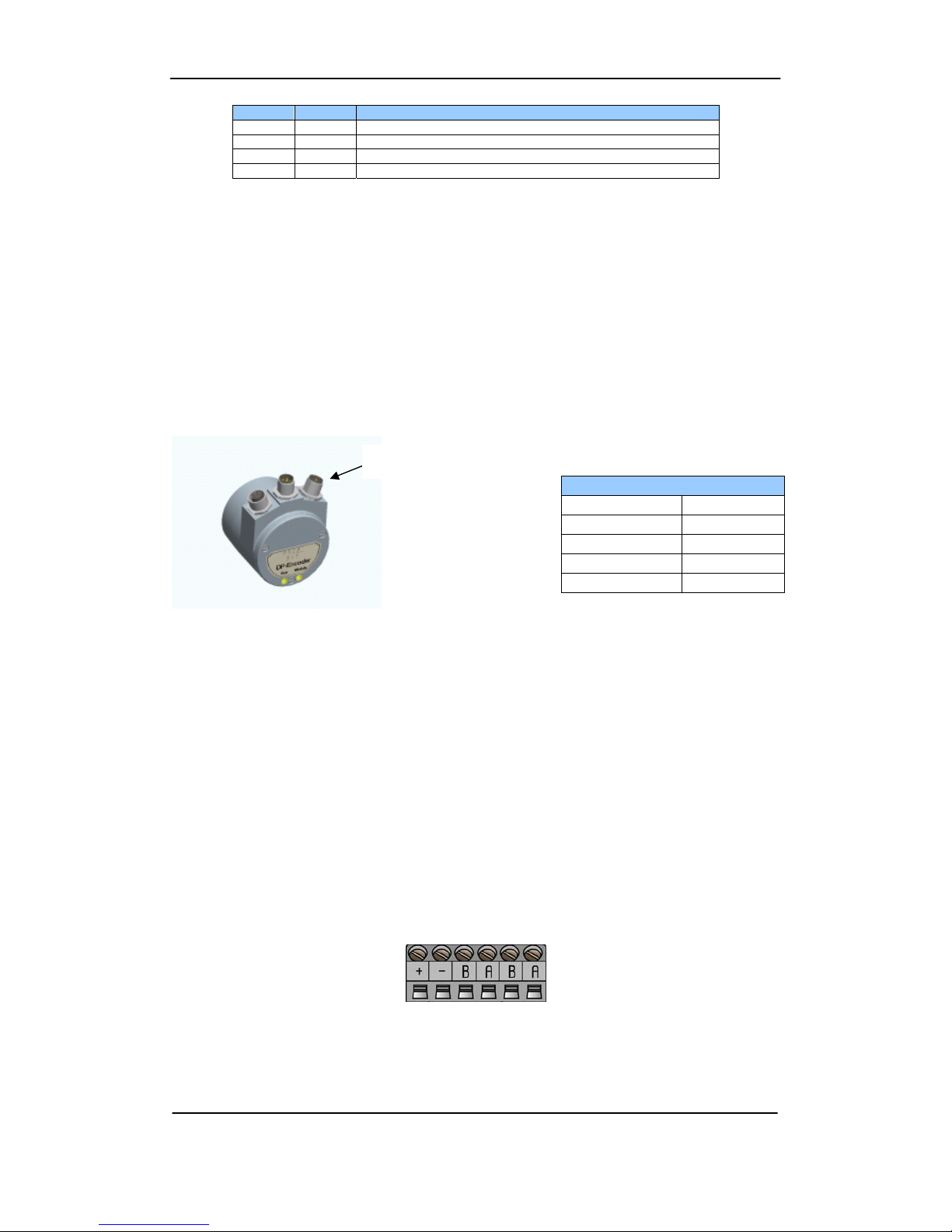
3.2 Connecting the encoder
3.2.1 Power supply
The power supply connection of M12 equipped encoders are constituted by a male A-
coded 4 pin M12 connector.
Picture 8 Orientation of M12 power supply connector
Encoders equipped with cable glands are delivered with a dust protection foil from
the factory. The protection foil needs to be removed prior to install the cables.
The cable gland encoders should always be equipped with a shielded power supply
cable with conductor area between 0,34mm2to 1.5mm2. Permissible outer cable
diameter is ø 6 mm to ø8 mm for the power supply cable. Located inside the back
cover are two screw terminals containing the required power supply terminals
marked (+) and (-).
In the case were the encoder is the last node in the bus-structure and only the cable
glands for Supply and Bus-in is in use, the Bus out cable gland should be replaced
with a filler plug to ensure proper sealing. The filler plug is available as an accessory
from Leine & Linde.
The (+) terminal shall be used to connect the +EV-line (9-36Vdc).
The (-) terminal shall be used to connect the 0V-line.
Picture 9 Terminal connection of power supply cables
Note: Tighten all screws in the terminal, even if no cable has been attached.
Power supply M12 version
Function Pin
+EV (9-36Vdc) 1
Not connected 2
0V 3
Not connected 4
Table 7 Pinning M12 power supply
Power supply

PROFIBUS USER MANUAL Leine & Linde AB
Part Id: 740590-01 15
Document Id: 740590 Ver. 01
Publication date: 2010-06-01
3.2.1 BUS lines
The PROFIBUS bus line connections of the M12 equipped devices are constituted by a
male B-coded 5 pin M12 connector (bus in), and a female B-coded 5 pin M12 connector
(bus out).
Picture 10 Orientation of M12 bus connectors
The cable gland encoders shall be equipped with twisted pair shielded cable in
accordance with EN 50170 and PROFIBUS guidelines. The guidelines recommend a
conductor area higher than 0,34mm2. Permissible outer cable diameter is ø 8 mm to ø
10 mm for the bus line cables. Located inside the back cover are four screw terminals
containing the required bus line terminals marked (A) and (B). Cable glands not used
should be replaced with a filler plug to ensure proper sealing. The filler plug is
available as an accessory from Leine & Linde.
The (A) terminal shall be used to connect the A-line.
The (B) terminal shall be used to connect the B-line.
Picture 11 Terminal connection of bus line cables
Note: Tighten all screws in the terminal, even if no cable has been attached.
Note: The two A-terminals are internally connected to each other and the two B-
terminals are also internally connected to each other so it does not matter to
which terminal the bus lines are connected to.
3.3 Shielding philosophy
To achieve the highest possible noise immunity and resistance against other EMI
related disturbances the bus and power supply cables shall always be shielded.
The screen should be connected to ground on both ends of the cable. In certain cases
compensation current might flow over the screen. Therefore a potential
compensation wire is recommended.
Bus in- lines Bus out- lines
Function Pin Function Pin
Not connected
1 VP 1
A 2 A 2
Not connected
3 DGND 3
B 4 B 4
Chassi 5 Chassi 5
Table 8
Pinnin
g
M12 bus in/out
–
lines
Bus
out Bus in

PROFIBUS USER MANUAL Leine & Linde AB
Part Id: 740590-01 16
Document Id: 740590 Ver. 01
Publication date: 2010-06-01
3.4 GSD-files
Absolute encoders with PROFIBUS can be configured and parameterized
corresponding to the requirements of the user. When the system is started, the
PROFIBUS devices are set and configured in DDLM_Set_Prm mode, i.e. the encoder
class set by means of the GSD file in the configuration tool and the operating
parameters are transferred to the respective slave.
Available GSD files can be downloaded from www.leinelinde.com
GSD file
Encoder functionality GSD file
Integrated encoder, DPV0 enc_a401.gsd
(llpba401.gsd)
Table 9 Available GSD file for DPV0 encoders
When configuring the encoders various encoder classes can be selected as described
in chapter 4. Selectable parameters and functionality of the device depend on the
selected encoder class. This data, saved in the PROFIBUS master is transferred once to
the encoder when the system is powered on. If the encoder has been started with the
GSD file for DPV0 functionality and a GSD file with a different ID-number shall be
used, the encoder needs to be restarted before it can use the new GSD file.
After the configuration and parameter data have been received the encoder enters
normal operation with cyclic data transfer i.e. "DDLM_Data_Exchange mode".
Installation of GSD-files:
1) Select and save the GSD file for the respective device from our homepage
www.leinelinde.com and then copy the *.gsd file into the respective directory
of the PROFIBUS configuration tool.
2) Select the bitmap file of the respective device on the floppy disk and copy the
*.bmp file into the respective directory of the PROFIBUS configuration tool.
3) Update the GSD files (SCAN).

PROFIBUS USER MANUAL Leine & Linde AB
Part Id: 740590-01 17
Document Id: 740590 Ver. 01
Publication date: 2010-06-01
3.5 LED indication
In order to determine the status of the encoder two LEDs are visible from the rear end
of the encoder. The module LED indicates status of the module itself. The bus LED
indicates the status of the bus. The table below defines the diagnostic messages using
a red (BUS) and a bicolor, Red/Green, LED (MODULE).
Bus Module
Meanin
g
Cause
Off Off No Power
Red Green No connection to another device
Criterion: no data exchange
- Bus disconnected
- Master not available / switched off
Red
2)
Red
2)
No connection to another device
No connection between EnDat
encoder and PROFIBUS PCB
- No connection to EnDat Encoder at
power up
Blinking Red
1 )
Green Parameterization or configuration
fault
- Configuration received differs from
the supported configuration.
- Parameter error in the
parameterization.
Green Red
System Failure - Diagnosis exists, slave in data
Exchange mode
- Position error
Green Green Data exchange.
Slave and operation ok.
Table 10 LED indication
1) The blinking frequency is 0.5 Hz. Minimal indication time is 3 sec.
2) Position error is when an alarm occurs in the encoder or if the EnDat encoder is
disconnected from the PROFIBUS interface PCB.

PROFIBUS USER MANUAL Leine & Linde AB
Part Id: 740590-01 18
Document Id: 740590 Ver. 01
Publication date: 2010-06-01
4 Profile overview
Encoder Profile for DPV0, version 1.1, Order no 3.062.
The operating functions in this profile are divided into two device classes named
Class 1 and Class 2. Class 1 encoders offer basic functions that all PROFIBUS-DP
encoders must support. An encoder of class 1 can optionally support selected
functions of class 2 but these functions must be implemented according to the
profile. To support early PROFIBUS-DP implementations the size of the protocol data
units (PDU) is limited to 16 bytes. Encoders of class 2 must support all functions of
class 1 as well as the additional functionality of class 2. In addition to the two classes,
parameters and diagnostic ranges are reserved for manufacturer-specific functions.
For further information regarding the encoder functionality refer to the device profile.
The profile and PROFIBUS technical information can be ordered at PNO in Karlsruhe,
Germany (www.profibus.com).
Picture 12 Overview encoder profile and related documents

PROFIBUS USER MANUAL Leine & Linde AB
Part Id: 740590-01 19
Document Id: 740590 Ver. 01
Publication date: 2010-06-01
4.1 DPV0 encoder classes
The device can be configured as a class 1 or class 2 PROFIBUS slave device. Class 2
configuration is extended to optionally access velocity information from the encoder.
CLASS 1 In the CLASS 1 configuration, only input data are assigned. Depending
on the encoder resolution, this is one input data word (16 bits) or two (32
bits).
The following functions can be performed:
•Changed direction of counting (Code sequence)
•Diagnostic data up to octet 16
Configuration data:
Singleturn Class 1 – 16 Bit: D0hex, 1 input data word, data consistency
Multiturn Class 1 – 32 Bit: D1hex, 2 input data words, data consistency
CLASS 2 In the CLASS 2 configuration output data values and input data words
are transferred. Depending on the encoder resolution, this is one input
data word (16 bits) and one output data word (16 bits) or two input data
words (32 bits) and two output data words (32 bits).
The following functions are available in addition to the class 1
functions:
•Scaling function
•Preset Value Function
•Velocity read-out
•Extended diagnostic data
Configuration data:
Singleturn Class 2 – 16 bits: F0hex, 1 input data word, 1 output data word
for preset value, data consistency
Multiturn Class 2 – 32 bits: F1hex, 2 input data word, 2 output data words
for preset value, data consistency
Position + Class 2 – 32+16 bits: F1+D0hex, 3 input data word, 2 output
velocity data words for preset value, data consistency
The selection of class depends on the demands required by the application but for
enabling full functionality of the device it is recommended to choose: Encoder class 2
32 bit + velocity.

PROFIBUS USER MANUAL Leine & Linde AB
Part Id: 740590-01 20
Document Id: 740590 Ver. 01
Publication date: 2010-06-01
5 Encoder and Gateway functionality, DPV0
5.1 Basic functionality
The Picture below gives an overview of the basic encoder and gateway functions and
how the functionality is conducted within the device.
Picture 13 Basic functionality
5.2 PROFIBUS data transfer principle
The PROFIBUS-DP devices can be configured and parameters can be set according to
the user's needs. In this context it is useful to know that with PROFIBUS there are
different types of data transmission.
5.2.1 During Configuration (DDLM_Chk_Cfg mode)
The configuration function allows the DP-Master to send the configuration data to the
DP-device for checking. The main purpose is to define the number of bytes used for
the Data_Exchange function.
5.2.2 During parameterization (DDLM_Set_Prm mode)
When the system is started, the PROFIBUS devices are parameterized (DDLM_Set_Prm
mode), i.e. the encoder class set by means of the GSD file in the configuration tool (see
chapter 4) and the set operating parameters (see chapter 5.4) are transferred to the
respective slave.
5.2.3 Normal operation (DDLM_Data-Exchange mode)
In the normal mode (DDLM_Data-Exchange mode), data are exchanged between
master and slaves. The preset function can be carried out only in this operating mode.
The data exchange is described in chapter 5.5.
5.3 Configuration, DPV0
The configuration of a DPV0 device is conducted by choosing encoder class, i.e. setting
the input/output data structure. The configuration options are 16-bit, 32-bit or 32-bit
+ 16-bit velocity input data, for explanation view chapter 4.1.
Table of contents
Popular Gateway manuals by other brands


Nortel
Nortel 3050 Implementation guide

Pepperl+Fuchs
Pepperl+Fuchs AS-I 3.0 PROFIBUS manual

ArtDio
ArtDio IPS-3101h user manual

Danfoss
Danfoss Ally Gateway user guide

Endress+Hauser
Endress+Hauser WirelessHART Fieldgate SWG70 operating instructions

Casa Systems
Casa Systems NetComm CloudMesh NL19MESH troubleshooting guide


