Proficient Audio Systems M4 User manual

16
1514
M4 QUICK START GUIDE
M4 SPECIFICATIONS
For technical inquiries, please call 877.888.9004 or email us at
techsupport@proficientaudio.com. We are available to assist you every
weekday, except holidays, between the hours of 7:00 a.m. and 5:00 p.m. PST.
940 Columbia Avenue, Riverside, CA 92507
877.888.9004 • Fax 951.787.8747 • proficientaudio.com
Audio Sections
Rated Power/Channel 30 Watts, 20Hz - 20kHz
(RMS, 2 channels driven into 8 Ω)
THD (at rated power) < 0.7%
Power/Channel 45 Watts @ 1kHz
(RMS, 2 channels driven into 4 Ω)
Input Sensitivity 300 mV
(For rated power @ max VC)
Input Impedance (source inputs) > 22 k
Input Overload (source inputs) 2.5 V
Output Voltage @ Pre-Outs 1.7 V, VC Setting, VC Max
(w/300 mV @ source inputs) 810 mV, NVC Setting
Output Impedance (pre-outs) < 300
Frequency Response (@ 1 watt @ 8 Ω) 20Hz - 20kHz ± 1.5dB
Channel Separation > 50dB @ 10kHz
Crosstalk Between Sources > 65dB @ 10kHz
S/N Ratio (re: rated output, > 95dB (VC 20dB IEC A,
source inputs shorted) below FCW)
Bass Control Range ±10dB @ 100Hz
Treble Control Range ±10dB @ 10kHz
Control Sections
Contact Closures (dry) 2A, 30V AC/DC Max
Phone Page In Audio Line Level, > 22 k
– Voltage/Impedance
Doorbell/Status In 1 & 2, 10 mA @ 12V AC/DC
3V - 30V AC or DC
Common IR Out
– HI (high power) 9 V Active High, 82 (110 mA Peak)
– LO (emitter power) 9 V Active High, 670 (13 mA Peak)
Zone IR Outs 9.2 V Active High, 620 (13 mA Peak)
– Voltage/Impedance
Source IR Outs (and loop) 11.5 V Active High, 390 (29 mA Peak)
– Voltage/Impedance
Common Status Out 9.5 V @ 100 mA
(0-12V DC)
General
Power Consumption
No Signal (idle) 50 Watts
At 1/8 Rated Power 110 Watts
(3.75 watts/channel)
Line Ratings (120V AC version) 120V AC, 1.8A
Rear Panel Fuse (120V AC version) T5AL 250V
Line Ratings (230V AC versions) 230V AC, 0.9A
Rear Panel Fuse (230V AC versions) T2.5AL 250V
Dimensions (H x W x D) 513 ⁄16" x 17⁄" x 151⁄2"
148mm x 435mm x 394mm
Weight 20 lbs (9.1 kg)
Limited Two-Year Warranty
Proficient Audio Systems warrants to the original retail purchaser only that this product will
be free from defects in materials and workmanship for a period of two years, provided the
speaker was purchased from a Proficient Audio Systems Authorized Dealer.
Defective products must be shipped, prepaid and insured, together with proof of purchase,
to the Proficient Audio Systems Authorized Dealer from whom they were purchased, or to
Proficient Audio Systems at the address listed on this installation instruction manual. Freight
collect shipments will be refused. It is preferable to ship this product in the original shipping
container to lessen the chance of transit damage. In any case, the risk of loss or damage in transit
is to be borne by the purchaser.
If, upon examination at the Factory or Proficient Audio Systems Authorized Dealer, it is
determined that the unit was defective in materials or workmanship at any time during this
warranty period, Proficient Audio Systems or the Proficient Audio Systems Authorized Dealer
will, at its option, repair or replace this product at no additional charge, except as set forth
below. If this model is no longer available and can not be repaired effectively, Proficient Audio
Systems, at its sole option, may replace the unit with a current model of equal or greater value.
In some cases where a new model is substituted, a modification to the mounting surface may
be required. If mounting surface modification is required, Proficient Audio Systems assumes
no responsibility or liability for such modification. All replaced parts and product become the
property of Proficient Audio Systems. Products replaced or repaired under this Warranty will
be returned to the original retail purchaser, within a reasonable time, freight prepaid.
This Warranty does not include service or parts to repair damage caused by accident, disaster,
misuse, abuse, negligence, inadequate packing or shipping procedures, commercial use, volt-
age inputs in excess of the rated maximum of the unit, or service, repair or modification of the
product which has not been authorized or approved by Proficient Audio Systems. This Warranty
also excludes normal cosmetic deterioration caused by environmental conditions. This warranty
will be void if the Serial Number on the product has been removed, tampered with or defaced.
This Warranty is in lieu of all other expressed warranties. If the product is defective in materials
or workmanship as warranted above, the purchaser’s sole remedy shall be repair or replacement
as provided above. In no event will Proficient Audio Systems be liable for any incidental or con-
sequential damages arising out of the use or inability to use the product, even if Proficient Audio
Systems, or a Proficient Audio Systems Authorized Dealer has been advised of the possibility of
such damages, or for any claim by any other party. Some states do not allow the exclusion or
limitation of consequential damages, so the above limitation and exclusion may not apply.
All implied warranties on the product are limited to the duration of this expressed Warranty.
Some states do not allow limitation on the length of an implied warranty. If the original retail
purchaser resides in such a state, this limitation does not apply.
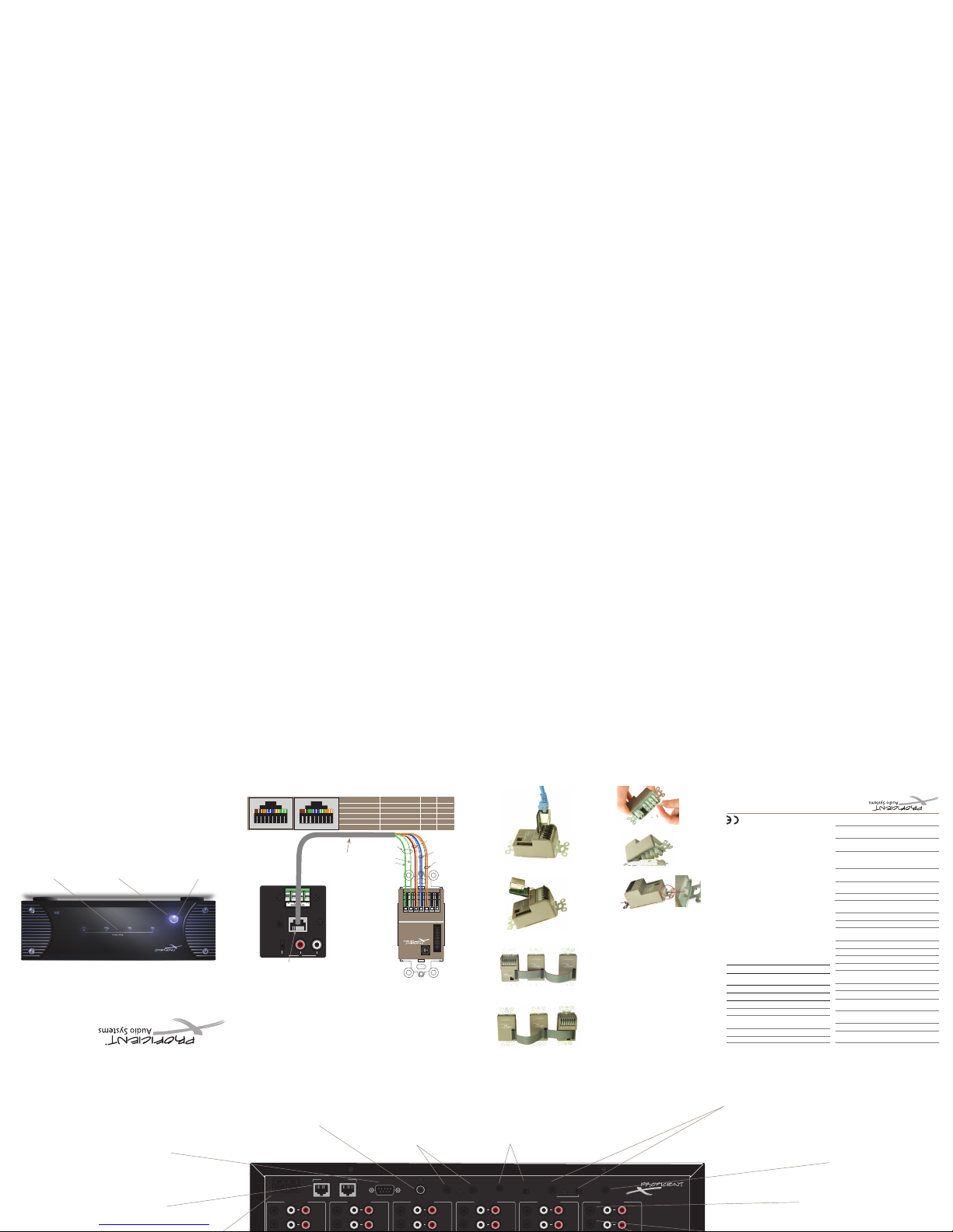
ZONE STATUS LEDS
LED indicators and labels:
Four blue LEDs indicate
that one or more zones
are currently active.
MASTER POWER SWITCH
When pressed in, the M4
permits zones to be turned
ON and OFF by keypad or
touch panel commands.
BLUE INDICATOR LIGHT
Blue indicates the master
power switch is ON and one
or more zones are active.
Red is OFF.
Keypad RJ45 T568B Standard T568A Standard
12V Pin 2, 7 Orange, White/Brown Green, White/Brown
DATA/IR Pin 4, 5 Blue, White/Blue Blue, White/Blue
GND Pin 1, 8 White/Orange, Brown White/Green, Brown
485A Pin 3 White/Green White/Orange
485B Pin 6 Green Orange
1 2 3 4 5 6 7 8
T568A Standard
1 2 3 4 5 6 7 8
T568B Standard
SPKRS
LR+
+ – –
ZONE 4
L R PRE-OUT
VC
NVC
KEYPAD
IR OUT
PMKIR
Master Keypad
with IR Receiver
ADDRESS
KEYPAD EXPANSION
Riverside, CA. USA • Made in China
proficientaudio.com
+ RELAY
– RELAY
+12V
DATA
GND
485 A
485 B
M4
Keypad
Connector
Rear View
CAUTION:
Colors shown are based on
T568B RJ45 termination.
SEE CHART BELOW
for T568A and T568B
wiring termination.
Inter-Room
Twisted Pair
CAT5 Cable
1,000' (305m) Max.
Orange
White/Brown
Blue
White/Blue
Brown
White/Orange
White/Green
Use Twisted Pair
for 485A & 485B
Green
Figure 11 Ribbon Cable – PMKIR Right
Figure 12 Ribbon Cable – PMKIR Left
KEYPAD HOOKUP
NOTE: The numeric and function keypads will not
work on their own. They must be connected to a
master keypad using the 3-connector ribbon cable
supplied (included with each model). The cable is
symmetrical so it can be connected with the red
striped side up or down, to best fit the configuration.
Figure 11 shows it connected so that the PMKIR
master keypad will be to the right of the PNK numeric
and PFK function keypads when mounted, whereas
Figure 12 places the PMKIR to the left.
Figure 13 RJA-1.1 Adapter
Figure 14 RJA-1.1 Attached to Keypad and CAT5
Figure 15
Using CAT5 Cable to Connect PMKIR Keypads to M4
Figure 10 Moving and Placing Buttons
Figure 9 Remove Decorator Insert Panel
1. The keypads have a pre-installed set of buttons in
place. These may not match the source and function
arrangements you need or desire. To change them,
release the tabs on each end of the keypad, Figure 8,
and remove the decorator insert panel, exposing the
key buttons, Figure 9.
2. Starting with the Zone 1 PMKIR (master keypad),
and using the extra buttons supplied, if needed,
move and place the source and function buttons in
the arrangement you want. See Figure 10. When you
finish the arrangement, replace the decorator insert
panel over the buttons, being careful to see that the
buttons align correctly with the panel openings.
Press the panel down until the tabs “snap” into place.
3. Repeat these steps for each of the other zone
master keypads. Each zone can have its own unique
configuration… but, it is best to keep them as similar
as possible to simplify programming and operation.
4. In the same way, configure the buttons on the
numeric and function keypads (not included) that
you may chose to use in some zones.
5. Connect all keypads to their assigned zones on
the M4 as shown in Figure 7. Be sure to strip then
connect the various colored CAT5 leads to the correct
terminals on each keypad end. Refer to Figure 15.
CONFIGURE THE KEYPAD BUTTONS
NOTE 1: If you want to use RJ45 connectors for
connecting the CAT5 cable to the keypads, you can do
so by using the Proficient model RJA-1.1 RJ45-to-Wire Pin
Adapters. See Figure 13 and Figure 14. Simply insert the
RJA-1.1 pins into the keypad’s connection terminals and
snap the levers in place. Be sure to orient them correctly
as shown.
Figure 8 Release Tab
1301-72400 (rev1)
Figure 1
M4 Front Panel Features
RS232
PHONE (PAGE IN) DOORBELL / STATUS IN
12
CONTROL
PORT
FIRMWARE
UPGRADE
OFF ON
COMMON
IR OUT
LO HI
STATUS OUT: 0 to +12V
120V 60Hz 1.8A ~
FUSE: T5AL 250V
DATA I/O
CONTACT CLOSURE
EXPANSION PORTS
COMMON
M4
SOURCE 1
LOOP
OUT
IR
LOOP
L R
INPUTS
SOURCE 2
LOOP
OUT
IR
LOOP
L R
INPUTS
SOURCE 3
LOOP
OUT
IR
LOOP
L R
INPUTS
SOURCE 4
LOOP
OUT
IR
LOOP
L R
INPUTS
SOURCE 5
LOOP
OUT
IR
LOOP
L R
INPUTS
SOURCE 6
LOOP
OUT
IR
LOOP
L R
INPUTS
SPKRS
LR+
+ – –
ZONE 4
L R PRE-OUT
VC
NVC
KEYPAD
IR OUT
Riverside, CA. USA
Made in Taiwan
SPKRS
LR+
+ – –
ZONE 3
L R PRE-OUT
VC
NVC
KEYPAD
IR OUT
SPKRS
LR+
+ – –
ZONE 2
L R PRE-OUT
VC
NVC
KEYPAD
IR OUT
SPKRS
LR+
+ – –
ZONE 1
L R PRE-OUT
VC
NVC
KEYPAD
IR OUT
5
4
3
2
M4 FEATURES
M4 Multi-Zone Audio Amplifier/Controller
The M4 is a four-zone, six-source Audio Amplifier/Controller. It serves as the
“brains” of the entire keypad system. The M4 provides audio switching for
six sources and 30W/channel audio power amplifiers for four zones. It also
has connection termination facilities for the controlled whole house system.
DOORBELL/STATUS IN 1 & 2 JACKS
These 3.5mm mini phone trigger inputs work in
conjunction with the PHONE PAGE IN jack. When
triggered, the phone inputs can be turned on as
programmed by Proficient Editor. If audio paging is
not required, these 1 & 2 jacks may also be pogrammed
as STATUS inputs for power management of source or
zone components. They accept input levels of 3V to 30V
AC or DC for the trigger ON condition. The voltage level
must drop below 1V AC or DC for the OFF condition.
IR OUT
This 3.5mm mini jack, one for each zone, provides dedicated Zone IR
output initiated from the respective zone inputs. They may control
specific zone components when you want to prevent the control of it
from the other zones.
EXPANSION PORTS
RJ45 jacks provide for connection
of specialized RS485 controlled
products and for looping to
additional M4 controllers for zone
expansion capability.
RS-232 DATA I/O
Communication port.
PHONE PAGE IN JACK
This jack provides input porting for audio feeds from
door mikes or other forms of phone or doorbell
paging. The jack is programmable by Proficient
Editor, to turn on as events, when triggered by the
DOORBELL/STATUS IN Jack.
CONTACT CLOSURE
Provides a single pole dry relay
contact to activate any device that
can be controlled or triggered by a
switch closure. The closure can be
programmed within Proficient Editor
to be activated by keypad presses,
Command Library IR, or within macros
for Momentary, Toggle and Open/
Close Paired operations. Spring-loaded
terminals accept wire sizes from 28 to 14
AWG. Internal relay contacts are rated at
2A/30V AC or DC.
CONTROL PORT & FIRMWARE UPGRADE SWITCH
3.5mm 4-circuit mini phone jack allows several control functions. All keypad
programming is accomplished via this port using Proficient Editor in conjunction
with the mating Transfer Cable. It also accommodates factory firmware updates
in conjunction with the FIRMWARE UPGRADE OFF/ON Switch. Be sure to leave
this switch in the OFF position at all times, except, as instructed within Proficient
Editor, when you are doing a firmware update. Such updates ensure that you can
always have the latest functionality improvements in the field. Another function of
this port is that you can control installed system components with bi-directional
data via touch panels or computers using RS232 protocol.
COMMON IR OUTPUT & HI/LO SWITCH
3.5mm mini phone jack provides a common IR output derived from all of
the zone IR inputs and from keypad initiated IR commands derived from
the internal IR library. High or low IR power output is set by means of the
HI/LO switch. Set it to the LO setting when driving standard low power
emitters (i.e, Proficient IR single flasher). Set it to the HI position when
driving a high power emitter (i.e, a blaster) for teaching IR commands into
learning remotes. Caution: The HI position will damage or destroy low
power emitters!
COMMON STATUS OUT PORT
This 3.5mm mini phone jack will go high (+12V DC)
when any zone is turned ON and will go LOW (under 1V
DC) when the last zone is turned OFF. The max. output
of this jack is 100 mA at 9.5V DC.
IR OUT JACKS
These 3.5mm mini phone jacks, one for each source, provide
dedicated IR output to specific source components. When a
source is selected on a keypad, IR function commands are
routed directly to that source. This prevents cross-control
interference between two or more sources that have
identical IR commands.
IR LOOP JACKS
These six 3.5mm mini phone jacks, one for each source, are
provided exclusively for zone expansion capability when
using two or more M4 controllers. They permit the
source IR signals from the added zones to be carried to
the source component emitters.
L & R AUDIO IN & LOOP JACKS
These RCA jacks – four for each source – provide audio
signal inputs and buffered loop outputs, for each
source. The buffered outputs can be used to drive local
components or loop the signals to the additional zone
inputs of other M4 controllers when using them for source
expansion.
IEC TYPE AC
Mains receptacle and fuse mates with included AC
power cord. Also houses the rear panel replaceable AC
mains fuse (T5AL 250V for 120V, and T2.5AL 250V for
230V/240V)
L & R PRE-OUT JACKS
These RCA jacks provide line level
audio outputs for driving external
power amplifiers for additional rooms
within zones, where needed.
VCNVC SWITCH
The audio output from the PRE-OUT jacks can
either be controlled by the internal volume
control of the M4 (VC position) or be a fixed
line level output in the no volume control
(NVC position). In either case, the tone control
remains available for room “EQ” settings.
KEYPAD ZONE INPUTS
These RJ45 terminals allow for easy
connection of the inter-room wiring
from keypads in the various rooms.
Normally this is accomplished using
CAT5 cable with home-run lengths of
up to 1000'.
L & R SPEAKERS TERMINALS
These 4-circuit plugable screw-down
terminals accept wire sizes from 14 to
28 AWG. They allow quick connection of
the internal amplifiers to stereo pairs of
speakers in the various zone rooms.
Figure 2
M4 Rear Panel Features
16
1514
M4 QUICK START GUIDE
M4 SPECIFICATIONS
For technical inquiries, please call 877.88 8.9004 or email us at
weekday, except holidays, between the hours of 7:00 a.m. and 5:00 p.m. PST.
940 Columbia Aven ue, Riverside, CA 92507
877.888.9004 • Fax 951.787.8747 • proficientaud io.com
Audio Sections
Rated Power/Channel 30 Watts, 20Hz - 20kHz
(RMS, 2 channels driven into 8 Ω)
THD (at rated power) < 0.7%
Power/Channel 45 Watts @ 1kHz
(RMS, 2 channels driven into 4 Ω)
Input Sensitivity 300 mV
(For rated power @ max VC)
Input Impedance (source inputs) > 22 k
Input Overload (source inputs) 2.5 V
Output Voltage @ Pre-Outs 1.7 V, VC Setting, VC Max
(w/300 mV @ source inputs) 810 mV, NVC Setting
Output Impedance (pre-outs) < 300
Frequency Response (@ 1 watt @ 8 Ω) 20Hz - 20kHz ± 1.5dB
Channel Separation > 50dB @ 10kHz
Crosstalk Between Sources > 65dB @ 10kHz
S/N Ratio (re: rated output, > 95dB (VC 20dB IEC A,
source inputs shorted) below FCW)
Bass Control Range ±10dB @ 100Hz
Treble Control Range ±10dB @ 10kHz
Control Sections
Contact Closures (dry) 2A, 30V AC/DC Max
Phone Page In Audio Line Level, > 22k
– Voltage/Impedance
Doorbell/Status In 1 & 2, 10 mA @ 12V AC/DC
3V - 30V AC or DC
Common IR Out
– HI (high power) 9 V Active High, 82 (110 mA Peak)
– LO (emitter power) 9 V Active High, 670 (13 mA Peak)
Zone IR Outs 9.2 V Active High, 620 (13mA Peak)
– Voltage/Impedance
Source IR Outs (and loop) 11.5 V ActiveHigh,390 (29mA Peak)
– Voltage/Impedance
Common Status Out 9.5 V @ 100 mA
(0-12V DC)
General
Power Consumption
No Signal (idle) 50 Watts
At 1/8 Rated Power 110 Watts
(3.75 watts/channel)
Line Ratings (120V AC version) 120V AC, 1.8A
Rear Panel Fuse (120V AC version) T5AL 250V
Line Ratings (230V AC versions) 230V AC, 0.9A
Rear Panel Fuse (230V AC versions) T2.5AL 250V
Dimensions (H x W x D) 513⁄16" x 17⁄" x 151⁄2"
148mm x 435mm x 394mm
Weight 20 lbs (9.1 kg)
Limited Two-Year Warranty
Proficient Aud io Systems warrants to the ori ginal retail purchase r only that this product w ill
be free from de fects in materials and wo rkmanship for a perio d of two years, provide d the
speaker was purch ased from a Proficient A udio Systems Authorized De aler.
Defective product s must be shipped, prepaid and insured, to gether with proof of purchase,
to the Proficient Audio Systems Authorized D ealer from whom they were purchased, or to
Proficient Audio Systems at the address lis ted on this installation instruction manual . Freight
collect shipments will be r efused. It is preferable to ship this produc t in the original shipping
container to lessen the chance of transit dama ge. In any case, the risk of loss or damage in transit
is to be borne by the purchaser.
If, upon examina tion at the Factory or Prof icient Audio Systems Author ized Dealer, it is
determined tha t the unit was defective in m aterials or workmanshi p at any time during this
warranty per iod, Proficient Audi o Systems or the Proficient Au dio Systems Authorized De aler
will, at its optio n, repair or replace this p roduct at no additiona l charge, except as set for th
below. If this mode l is no longer available an d can not be repaired ef fectively, Profici ent Audio
Systems, at its sol e option, may replace the uni t with a current model of eq ual or greater value.
In some cases whe re a new model is substitute d, a modification to th e mounting surface may
be required. I f mounting surface mo dification is requir ed, Proficient Audio Sys tems assumes
no responsibil ity or liability for s uch modification . All replaced parts an d product become the
propert y of Proficient Audio Syste ms. Products replace d or repaired under this War ranty will
be returned to th e original retail purch aser, within a reasonable tim e, freight prepaid.
This Warranty does not inc lude service or parts to repa ir damage caused by accident, disaster,
misuse, abuse, negligen ce, inadequate packing or shipping pr ocedures, commercial use, volt-
age inputs in excess of the rate d maximum of the unit, or service, re pair or modification of the
product which has not be en authorized or approved by Profi cient Audio Systems. This Warranty
also excludes normal cosme tic deterioration caused by environm ental conditions. This warrant y
will be void if the Serial Num ber on the product has been remove d, tampered with or defaced.
This Warranty is in lieu of all other ex pressed warranties. If the product is de fective in materials
or workmanship as warranted above, the p urchaser’s sole remedy shall be repair or repl acement
as provided above. In no event will Profi cient Audio Systems be liable for any incidental or con-
sequential damages arising out of th e use or inability to use the product, even if Pro ficient Audio
Systems, or a Proficient Audio Systems Authori zed Dealer has been advised of the possibi lity of
such damages, or for any claim by any other par ty. Some states do not allow the exclusion or
limitation of consequential damage s, so the above limitation and exclusion may not apply.
All implied war ranties on the product a re limited to the duration of th is expressed Warrant y.
Some states do no t allow limitation on the le ngth of an implied warra nty. If the original retai l
purchaser resid es in such a state, this limita tion does not apply.
ZONE STATUS LEDS
LED indicators and labels:
Four blue LEDs indicate
that one or more zones
are currently active.
MASTER POWER SWITCH
When pressed in, the M4
permits zones to be turned
ON and OFF by keypad or
touch panel commands.
BLUE INDICATOR LIGHT
Blue indicates the master
power switch is ON and one
or more zones are active.
Red is OFF.
Keypad RJ45 T568B Standard T568A Standard
12V Pin 2, 7 Orange, White/Brown Green, White/Brown
DATA/IR Pin 4, 5 Blue, White/Blue Blue, White/Blue
GND Pin 1, 8 White/Orange, Brown White/Green, Brown
485A Pin 3 White/Green White/Orange
485B Pin 6 Green Orange
1 2 3 4 5 6 7 8
T568A Standard
1 2 3 4 5 6 7 8
T568B Standard
SPKRS
LR+
+ – –
ZONE 4
L R PRE-OUT
VC
NVC
KEYPAD
IR OUT
PMKIR
Master Keypad
with IR Receiver
ADDRESS
KEYPAD EXPANSION
Riverside, CA. USA • Made in China
proficientaudio.com
+ RELAY
– RELAY
+12V
DATA
GND
485 A
485 B
M4
Keypad
Connector
Rear View
CAUTION:
Colors shown are based on
T568B RJ45 termination.
SEE CHART BELOW
for T568A andT568B
wiring termination.
Inter-Room
Twisted Pair
CAT5 Cable
1,000' (305m) Max.
Orange
White/Brown
Blue
White/Blue
Brown
White/Orange
White/Green
Use Twisted Pair
for 485A & 485B
Green
Figure 11 Ribbon Cable – PMKIR Right
Figure 12 Ribbon Cable – PMKIR Left
KEYPAD HOOKUP
NOTE: The numeric and function keypads will not
work on their own. They must be connected to a
master keypad using the 3-connector ribbon cable
supplied (included with each model). The cable is
symmetrical so it can be connected with the red
striped side up or down, to best fit the configuration.
Figure 11 shows it connected so that the PMKIR
master keypad will be to the right of the PNK numeric
and PFK function keypads when mounted, whereas
Figure 12 places the PMKIR to the left.
Figure 13 RJA-1.1 Adapter
Figure 14 RJA-1.1 Attached to Keypad and CAT5
Figure 15
Using CAT5 Cable to Connect PMKIR Keypads to M4
Figure 10 Moving and Placing Buttons
Figure 9 Remove Decorator Insert Panel
1. The keypads have a pre-installed set of buttons in
place. These may not match the source and function
arrangements you need or desire. To change them,
release the tabs on each end of the keypad, Figure 8,
and remove the decorator insert panel, exposing the
key buttons, Figure 9.
2. Starting with the Zone 1 PMKIR (master keypad),
and using the extra buttons supplied, if needed,
move and place the source and function buttons in
the arrangement you want. See Figure 10. When you
finish the arrangement, replace the decorator insert
panel over the buttons, being careful to see that the
buttons align correctly with the panel openings.
Press the panel down until the tabs “snap” into place.
3. Repeat these steps for each of the other zone
master keypads. Each zone can have its own unique
configuration… but, it is best to keep them as similar
as possible to simplify programming and operation.
4. In the same way, configure the buttons on the
numeric and function keypads (not included) that
you may chose to use in some zones.
5. Connect all keypads to their assigned zones on
the M4 as shown in Figure 7. Be sure to strip then
connect the various colored CAT5 leads to the correct
terminals on each keypad end. Refer to Figure 15.
CONFIGURE THE KEYPAD BUTTONS
NOTE 1: If you want to use RJ45 connectors for
connecting the CAT5 cable to the keypads, you can do
so by using the Proficient model RJA-1.1 RJ45-to-Wire Pin
Adapters. See Figure 13 and Figure 14. Simply insert the
RJA-1.1 pins into the keypad’s connection terminals and
snap the levers in place. Be sure to orient them correctly
as shown.
Figure 8 Release Tab
1301-72400 (rev1)
Figure 1
M4 Front Panel Features
RS232
PHONE (PAGE IN) DOORBELL / STATUS IN
12
CONTROL
PORT
FIRMWARE
UPGRADE
OFF ON
COMMON
IR OUT
LO HI
STATUS OUT: 0 to +12V
120V 60Hz 1.8A ~
FUSE: T5AL 250V
DATA I/O
CONTACT CLOSURE
EXPANSION PORTS
COMMON
M4
SOURCE 1
LOOP
OUT
IR
LOOP
L R
INPUTS
SOURCE 2
LOOP
OUT
IR
LOOP
L R
INPUTS
SOURCE 3
LOOP
OUT
IR
LOOP
L R
INPUTS
SOURCE 4
LOOP
OUT
IR
LOOP
L R
INPUTS
SOURCE 5
LOOP
OUT
IR
LOOP
L R
INPUTS
SOURCE 6
LOOP
OUT
IR
LOOP
L R
INPUTS
SPKRS
LR+
+ – –
ZONE 4
L R PRE-OUT
VC
NVC
KEYPAD
IR OUT
Riverside, CA. USA
Made in Taiwan
SPKRS
LR+
+ – –
ZONE 3
L R PRE-OUT
VC
NVC
KEYPAD
IR OUT
SPKRS
LR+
+ – –
ZONE 2
L R PRE-OUT
VC
NVC
KEYPAD
IR OUT
SPKRS
LR+
+ – –
ZONE 1
L R PRE-OUT
VC
NVC
KEYPAD
IR OUT
5
4
3
2
M4 FEATURES
M4 Multi-Zone Audio Amplifier/Controller
The M4 is a four-zone, six-source Audio Amplifier/Controller. It serves as the
“brains” of the entire keypad system. The M4 provides audio switching for
six sources and 30W/channel audio power amplifiers for four zones. It also
has connection termination facilities for the controlled whole house system.
DOORBELL/STATUS IN 1 & 2 JACKS
These 3.5mm mini phone trigger inputs work in
conjunction with the PHONE PAGE IN jack. When
triggered, the phone inputs can be turned on as
programmed by Proficient Editor. If audio paging is
not required, these 1 & 2 jacks may also be pogrammed
as STATUS inputs for power management of source or
zone components. They accept input levels of 3V to 30V
AC or DC for the trigger ON condition. The voltage level
must drop below 1V AC or DC for the OFF condition.
IR OUT
This 3.5mm mini jack, one for each zone, provides dedicated Zone IR
output initiated from the respective zone inputs. They may control
specific zone components when you want to prevent the control of it
from the other zones.
EXPANSION PORTS
RJ45 jacks provide for connection
of specialized RS485 controlled
products and for looping to
additional M4 controllers for zone
expansion capability.
RS-232 DATA I/O
Communication port.
PHONE PAGE IN JACK
This jack provides input porting for audio feeds from
door mikes or other forms of phone or doorbell
paging. The jack is programmable by Proficient
Editor, to turn on as events, when triggered by the
DOORBELL/STATUS IN Jack.
CONTACT CLOSURE
Provides a single pole dry relay
contact to activate any device that
can be controlled or triggered by a
switch closure. The closure can be
programmed within Proficient Editor
to be activated by keypad presses,
Command Library IR, or within macros
for Momentary, Toggle and Open/
Close Paired operations. Spring-loaded
terminals accept wire sizes from 28 to 14
AWG. Internal relay contacts are rated at
2A/30V AC or DC.
CONTROL PORT & FIRMWARE UPGRADE SWITCH
3.5mm 4-circuit mini phone jack allows several control functions. All keypad
programming is accomplished via this port using Proficient Editor in conjunction
with the mating Transfer Cable. It also accommodates factory firmware updates
in conjunction with the FIRMWARE UPGRADE OFF/ON Switch. Be sure to leave
this switch in the OFF position at all times, except, as instructed within Proficient
Editor, when you are doing a firmware update. Such updates ensure that you can
always have the latest functionality improvements in the field. Another function of
this port is that you can control installed system components with bi-directional
data via touch panels or computers using RS232 protocol.
COMMON IR OUTPUT & HI/LO SWITCH
3.5mm mini phone jack provides a common IR output derived from all of
the zone IR inputs and from keypad initiated IR commands derived from
the internal IR library. High or low IR power output is set by means of the
HI/LO switch. Set it to the LO setting when driving standard low power
emitters (i.e, Proficient IR single flasher). Set it to the HI position when
driving a high power emitter (i.e, a blaster) for teaching IR commands into
learning remotes. Caution: The HI position will damage or destroy low
power emitters!
COMMON STATUS OUT PORT
This 3.5mm mini phone jack will go high (+12V DC)
when any zone is turned ON and will go LOW (under 1V
DC) when the last zone is turned OFF. The max. output
of this jack is 100 mA at 9.5V DC.
IR OUT JACKS
These 3.5mm mini phone jacks, one for each source, provide
dedicated IR output to specific source components. When a
source is selected on a keypad, IR function commands are
routed directly to that source. This prevents cross-control
interference between two or more sources that have
identical IR commands.
IR LOOP JACKS
These six 3.5mm mini phone jacks, one for each source, are
provided exclusively for zone expansion capability when
using two or more M4 controllers. They permit the
source IR signals from the added zones to be carried to
the source component emitters.
L & R AUDIO IN & LOOP JACKS
These RCA jacks – four for each source – provide audio
signal inputs and buffered loop outputs, for each
source. The buffered outputs can be used to drive local
components or loop the signals to the additional zone
inputs of other M4 controllers when using them for source
expansion.
IEC TYPE AC
Mains receptacle and fuse mates with included AC
power cord. Also houses the rear panel replaceable AC
mains fuse (T5AL 250V for 120V, and T2.5AL 250V for
230V/240V)
L & R PRE-OUT JACKS
These RCA jacks provide line level
audio outputs for driving external
power amplifiers for additional rooms
within zones, where needed.
VCNVC SWITCH
The audio output from the PRE-OUT jacks can
either be controlled by the internal volume
control of the M4 (VC position) or be a fixed
line level output in the no volume control
(NVC position). In either case, the tone control
remains available for room “EQ” settings.
KEYPAD ZONE INPUTS
These RJ45 terminals allow for easy
connection of the inter-room wiring
from keypads in the various rooms.
Normally this is accomplished using
CAT5 cable with home-run lengths of
up to 1000'.
L & R SPEAKERS TERMINALS
These 4-circuit plugable screw-down
terminals accept wire sizes from 14 to
28 AWG. They allow quick connection of
the internal amplifiers to stereo pairs of
speakers in the various zone rooms.
Figure 2
M4 Rear Panel Features
13
12
1110
SYSTEM CONNECTIONS AND CONFIGURATION
RS232
PHONE (PAGE IN) DOORBELL / STATUS IN
12
CONTROL
PORT
FIRMWARE
UPGRADE
OFF ON
COMMON
IR OUT
LO HI
STATUS OUT:
0 to +12V
120V 60Hz 1.8A~
FUSE: T5AL 250V
DATA I/O
CONTACT CLOSURE
EXPANSION PORTS
COMMON
M4
SOURCE 1
LOOP
OUT
IR
LOOP
L R
INPUTS
SOURCE 2
LOOP
OUT
IR
LOOP
L R
INPUTS
SOURCE 3
LOOP
OUT
IR
LOOP
L R
INPUTS
SOURCE 4
LOOP
OUT
IR
LOOP
L R
INPUTS
SOURCE 5
LOOP
OUT
IR
LOOP
L R
INPUTS
SOURCE 6
LOOP
OUT
IR
LOOP
L R
INPUTS
SPKRS
LR+
+ – –
ZONE 4
L R PRE-OUT
VC
NVC
KEYPAD
IR OUT
Riverside, CA. USA
Made in Taiwan
SPKRS
LR+
+ – –
ZONE 3
L R PRE-OUT
VC
NVC
KEYPAD
IR OUT
SPKRS
LR+
+ – –
ZONE 2
L R PRE-OUT
VC
NVC
KEYPAD
IR OUT
SPKRS
LR+
+ – –
ZONE 1
L R PRE-OUT
VC
NVC
KEYPAD
IR OUT
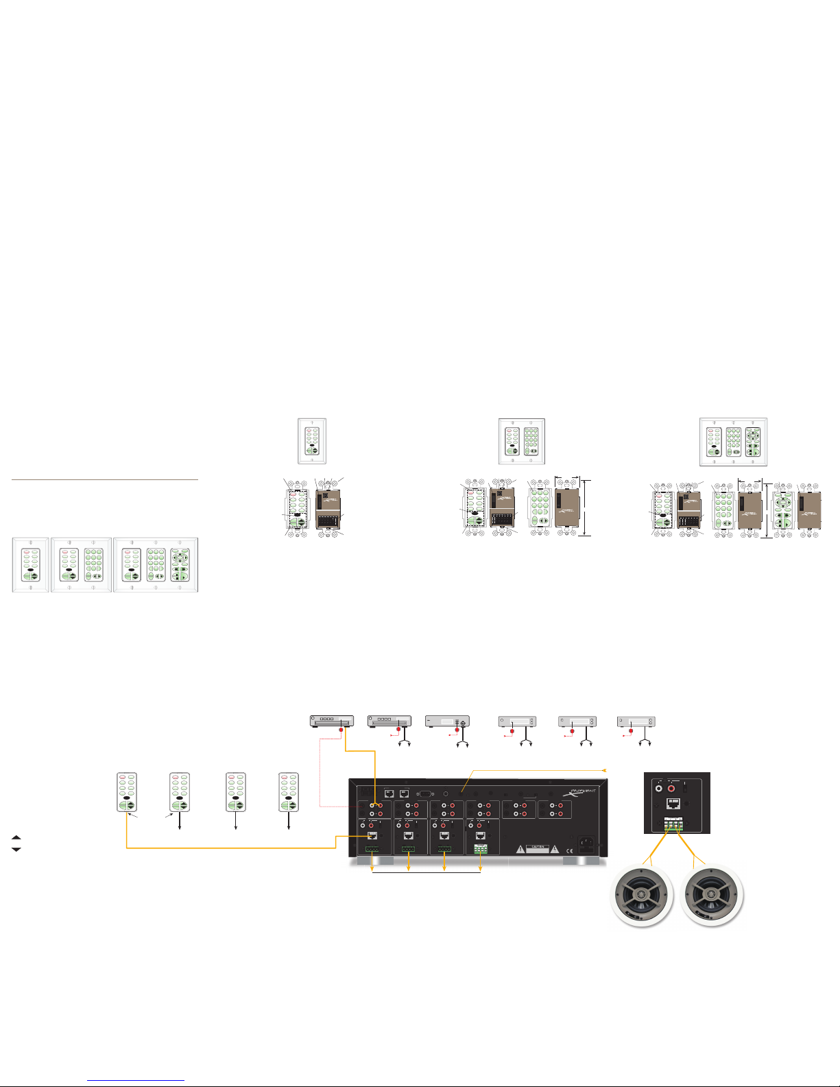
To
Zone 1
Keypad Jack
CAT5 Cable Carries
RS485 Control, IR Signal
and Keypad Power
From Doorbell Trigger
To Source 1
Inputs
L / R
IR Out from Source 1 IR Out from Source 2 IR Out from Source 3 IR Out from Source 4
TUNER 2
TUNER 1 SATELLITE CD PLAYER
Speaker Feeds to Each Zone
To Source 2
Inputs
L R
To Source 3
Inputs
L R
To Source 4
Inputs
L R
IR Out from Source 5
CD PLAYER 2
To Source 5
Inputs
L R
IR Out from Source 6
MP3 PLAYER
To Source 6
Inputs
L R
IR Flasher
Zone 1
PMKIR
Keypad
SAT CD
MUTE
TNR1 TNR2
PWR
CD2 MP3
BASS TREB
MUTE
PWR
SAT CD
TNR1 TNR2
CD2 MP3
BASS TREB
SAT CD
MUTE
TNR1 TNR2
PWR
CD2 MP3
BASS TREB
To
Zone 2
Keypad Jack
Zone 2
PMKIR
Keypad
SAT CD
MUTE
TNR1 TNR2
PWR
CD2 MP3
BASS TREB
MUTE
PWR
SAT CD
TNR1 TNR2
CD2 MP3
BASS TREB
SAT CD
MUTE
TNR1 TNR2
PWR
CD2 MP3
BASS TREB
To
Zone 3
Keypad Jack
Zone 3
PMKIR
Keypad
SAT CD
MUTE
TNR1 TNR2
PWR
CD2 MP3
BASS TREB
MUTE
PWR
SAT CD
TNR1 TNR2
CD2 MP3
BASS TREB
SAT CD
MUTE
TNR1 TNR2
PWR
CD2 MP3
BASS TREB
To
Zone 4
Keypad Jack
Zone 4
PMKIR
Keypad
SAT CD
MUTE
TNR1 TNR2
PWR
CD2 MP3
BASS TREB
MUTE
PWR
SAT CD
TNR1 TNR2
CD2 MP3
BASS TREB
SAT CD
MUTE
TNR1 TNR2
PWR
CD2 MP3
BASS TREB
Factory Default System
As mentioned earlier, the M4 comes with a set of four
pre-configured PMKIR keypads, one for each zone. In
addition, the M4 is pre-programmed at the factory
with a default project so that the entire system will
function “right out of the box.” The installer can use
this default as a base on which to build customized
projects. The default project has the following
functionality: (Refer to Figures 3 & 7).
1. Six Source keys: TNR1, TNR2, SAT, CD, CD2, MP3
2. Six Function keys: BASS, TREB, MUTE, PWR, VOL UP,
VOL DOWN
3. The six Source keys are set as Zone ON keys and
are programmed to select the M4 rear panel Audio
Source inputs as follows:
TNR1 = Audio Source 1, TNR2 = Audio Source 2,
SAT = Audio Source 3, CD = Audio Source 4, CD2 =
Audio Source 5, MP3 = Audio Source 6. In addition,
a Mute Off command is programmed under each
Source key.
4. The six Function keys are programmed as follows:
BASS: 1st press changes Vol UP/Down to Bass Up/
Down. 2nd press = Bass Flat.
TREB: 1st press changes Vol Up/Down to Treble Up/
Down. 2nd press = Treble Flat.
: Volume Up command. Also serves as Bass or
Treble Up after first pressing BASS or TREB keys.
: Volume Down command. Also serves as Bass
or Treble Down after first pressing BASS or TREB keys.
NOTE: While in the Treble or Bass tone modes, the
selected Source button will blink at a medium rate,
to indicate the tone setting mode. The tone setting
mode is defeated by one press of any button other
than the Tone and Volume buttons.
MUTE: Set for Internal Preamp Muting. Toggles
ON/OFF. Pressing Source and Volume buttons also
un-mutes. During Mute, selected source key blinks
slowly.
PWR: Set as Zone Power OFF. Will NOT turn the zone
ON. Press and Hold for two seconds turns all zones
OFF (Whole House).
Whole House/Party Mode
5. All zones are set for Whole House/Party Mode
capability Whole House/Party Mode: Forces all zones
to the same source and allows volume and mute
functions to operate all zones in unison.
- To engage Whole House/Party Mode, press and
hold a desired Source button for longer than two
seconds. During press and hold, source button
blinks rapidly (busy).
- Release button when blinking stops. Source
button then turns Amber in color, indicating
system is now in Whole House/Party Mode.
- Source selection, Volume Control and Mute
functions will now operate in all zones from the
initiating zone only.
- To transfer Whole House/Party Mode control to
another zone, above steps are repeated from the
desired zone.
- To cancel Whole House/Party Mode, press and
hold a Source button from the initiating zone for
longer than two seconds (until blinking stops).
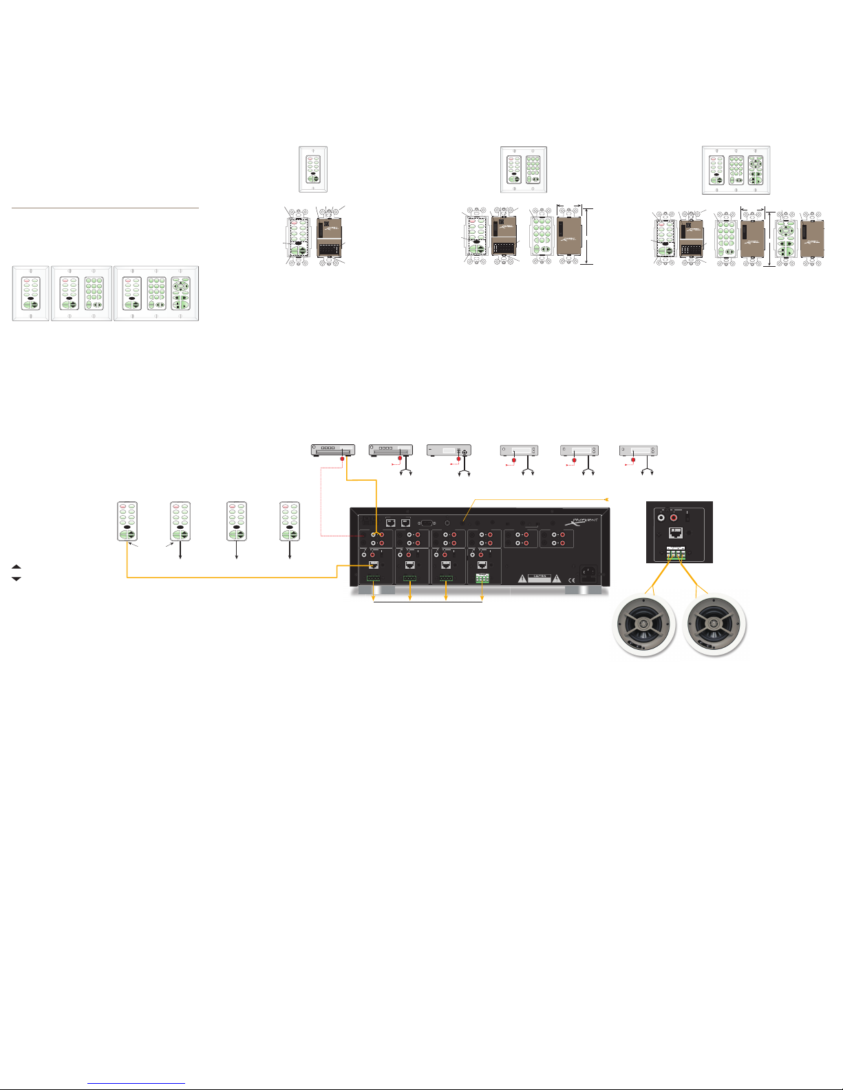
A TYPICAL M4 INSTALLATION
Perhaps the best way to become familiar with the
M4/keypad system is to show its application in a
typical installation. Figure 7 shows the four PMKIR
keypads (included) controlling the M4 and related
source components in a four-zone application
NOTE: The system in Figure 7 is given to illustrate
the basics on how to configure and program
a system, not to show all aspects of such an
installation. For instance, for simplicity, the speakers
in each zone are not shown in Figure 7, even though
such components would be required for a complete
working system.
NOTE: Maximum recommended lead length for the
keypads with CAT5 cable is 1000' (305m).
The recommended steps to install such a system
would be as follows:
1. Pull all wiring for the keypads, speakers, etc., from
the various zone rooms (home runs) to a central
equipment area.
2. Set up and make all the necessary audio
connections from the source components to the
M4, the amplifiers to speakers in rooms, etc.
3. Make sure all system components function first,
with their own remote controls, before configuring
the keypads.
4. Flasher placement: Locate each source
component’s IR Sensor window. Place emitters on
each of the source components and plug them into
the corresponding Source IR Outputs on the M4.
NOTE: Zones other than the initiating zone will have
red active Source buttons and will operate as normal
independent zones.
6. Priority is set to ON for all zones. This means
that commands from any keypad in any zone will
execute, regardless of previous command executions
in other zones.
7. When a zone is first turned on, the volume will be
at a default medium background level. After that, it
will come on at the last volume used prior to zone
turn OFF.
9
8
76
KEYPAD GANG CONFIGURATIONS
The M4 System comes with four single gang PMKIR
pre-configured keypads, one for each zone as shown
for the single gang version in Figure 3. The cover
plates and the other configurations are optional.
Screw-less “Snap-On” type cover plates are also
accommodated. Each keypad comes with a set of
factory installed “default buttons” plus a good variety
ofadditional buttons. The default buttons can be easily
changed to meet the needs of the installation.
PMKIR Master Keypad
(included with the M4)
MUTE
PWR
Rear View
0
1
2
3
4
5
6
7
8
9
A
B
C
D
E
F
SAT CD
TNR1 TNR2
CD2 MP3
BASS TREB
PMKIR
MasterKeypad
withIR Receiver
+RELAY
– RELAY
+12V
DATA
GND
485A
485B
ADDRESS
KEYPADEXPANSION
Riverside,CA. USA • Made in China
proficientaudio.com
SAT CD
MUTE
TNR1 TNR2
PWR
CD2 MP3
BASS TREB
SAT CD
MUTE
TNR1 TNR2
PWR
CD2 MP3
BASS TREB
1
6
8
PMKIR
(included)
PMKIR
MasterKeypad
withIR Receiver
+RELAY
– RELAY
+12V
DATA
GND
485A
485B
ADDRESS
KEYPADEXPANSION
Riverside,CA. USA • Made in China
proficientaudio.com
2 3 4
4
5
7
Single Gang Set-Up
1. PMKIR Source/Function Buttons – Six of this set
of eight buttons are programmed as source select
for the M4. When the system is off, all buttons have
a background green color. When a source button is
pressed, it turns to a low-level red color to show that
it is the active source and the system is on.
2. Keypad Expansion Terminal – This 16-pin header
terminal is used to inter-connect the optional numeric
and function keypad modules for expansion as
needed. A 3-connector ribbon cable is packed with
each module for making these connections.
3. Address Switch – A unique hex address must be
set for each master keypad when connected on a
common bus within a single zone. Unique addresses
are not required zone-to-zone. It provides up to 16
addresses (0 to F).
4. Snap Tabs – These tabs hold the decorator style
insert panel to the metal mounting plate and are
easily released for custom changing of the buttons.
5. Mounting Plate – Standard plate allows the
keypad module to be attached to standard in-wall
J-Boxes using the two screws provided. Allows
attachment of standard decorator type cover plates
(also screw-less snap-on plates).
6. IR Receiver Lens – Version PMKIR includes
Proficient’s exclusive ANS IR receiver, built-in. It allows
the use of a handheld remote for control of system
components.
7. Connection Terminals – for CAT5 home-run
termination. + Relay and – Relay - for future use.
+12V – Powers the keypad, including the internal IR
receiver on model PMKIR. Includes reverse voltage
protection. Data – Sends IR control signals for
control of system components. GND – Return for
power, IR signal and data. 485 A / 485 B – Balanced,
bi-directional system communications data.
8. Function Buttons – These lower four buttons (can
be programmed for any function except source select.)
The Proficient M4 System consists of four subsystems.
First, the keypads themselves can be configured in
many key icon arrangements and placed in a one,
two or three gang set-up to meet virtually any client
requirement. They are connected via convenient
CAT5 cable with home-run lengths of up to 1000'
(305m or longer, if heavier gauge wire is used) to the
centrally located M4 Multi-Zone Audio Amplifier/
Controller located near the controlled equipment.
The M4 contains the “brains” of the system, taking
key location data from the keypads to trigger the
actual controlling IR, RS232 and RS485 commands
that are passed to all of the installed system
components. Programming is accomplished by the
use of Proficient Editor, a Proficient developed
Windows software system. A fourth item, the
optional Command Interface (sold separately), is an
installer’s tool for learning and teaching special IR
commands that are not included in the Proficient
Editor internal library.
PMKIR PNK PFK
(included) (optional) (optional)
1 2 3
4 5 6
7 8 9
0
TRK DSC
RDM
RPT
PLAY
ESC INFO
MENUGUIDE
MUTE
PWR
PMKIR PNK
MUTE
PWR
1 2 3
4 5 6
7 8 9
0
TRK DSC
RDM
PMKIR
(included)
SAT CD
MUTE
TNR1 TNR2
PWR
SEL
CD2 MP3
BASS TREB
SAT CD
TNR1 TNR2
CD2 MP3
BASS TREB
GBL
RPT
SAT CD
TNR1 TNR2
CD2 MP3
BASS TREB
(included) (optional)
SAT CD
MUTE
TNR1 TNR2
PWR
CD2 MP3
BASS TREB
SAT CD
MUTE
TNR1 TNR2
PWR
CD2 MP3
BASS TREB
PLAY
ESC INFO
MENUGUIDE
SEL
1 2 3
4 5 6
7 8 9
0
DSC
RDM
RPT
TRK
1 2 3
4 5 6
7 8 9
0
DSC
RDM
RPT
TRK
Single Gang Double Gang Triple Gang
MUTE
PWR
1 2 3
4 5 6
7 8 9
0
TRK DSC
RDM
SAT CD
TNR1 TNR2
CD2 MP3
BASS TREB
GBL
RPT
SAT CD
MUTE
TNR1 TNR2
PWR
CD2 MP3
BASS TREB
1 2 3
4 5 6
7 8 9
0DISK
RND
RPT
TRK
PMKIR PNK
(included) (optional)
1.77"
4.07"
PNK Numeric Keypad
(Not included with M4)
1 2 3
4 5 6
7 8 9
0
TRK DSC
RDM
RPT
Rear View
9
KEYPADEXPANSION
Riverside,CA. USA • Made in China
proficientaudio.com
PNK
NumericKeypad
1 2 3
4 5 6
7 8 9
0DSC
RDM
RPT
TRK
PMKIR Master Keypad
(Included with M4)
Rear View
MUTE
PWR
SAT CD
TNR1 TNR 2
CD2 MP3
BASS TREB
GBL
0
1
2
3
4
5
6
7
8
9
A
B
C
D
E
F
PMK
MasterKeypad
+RELAY
– RELAY
+12V
DATA
GND
485A
485B
ADDRESS
KEYPADEXPANSION
Riverside,CA. USA • Made in China
proficientaudio.com
SAT CD
MUTE
TNR1 TNR 2
PWR
CD2 MP3
BASS TREB
2
1
3 4
6
7
4
8
5
PMKIR
MasterKeypad
withIR Receiver
+RELAY
– RELAY
+12V
DATA
GND
485A
485B
ADDRESS
KEYPADEXPANSION
Riverside,CA. USA • Made in China
proficientaudio.com
Double Gang Set-Up
1. PMKIR Source/Function Buttons – Six of this set
of eight buttons are programmed as source select
for the M4. When the system is off, all buttons have
a background green color. When a source button is
pressed, it turns to a low-level red color to show that
it is the active source and the system is on.
2. Keypad Expansion Terminal – This 16-pin header
terminal is used to inter-connect the optional numeric
and function keypad modules for expansion as
needed. A 3-connector ribbon cable is packed with
each module for making these connections.
3. Address Switch – A unique hex address must be
set for each master keypad when connected on a
common bus within a single zone. Unique addresses
are not required zone-to-zone. It provides up to 16
addresses (0 to F).
4. Snap Tabs – These tabs hold the decorator style
insert panel to the metal mounting plate and are
easily released for custom changing of the buttons.
5. Mounting Plate – Standard plate allows the
keypad module to be attached to standard in-wall
J-Boxes using the two screws provided. Allows
attachment of standard decorator type cover plates
(also screw-less snap-on plates).
6. IR Receiver Lens – Version PMKIR includes
Proficient’s exclusive ANS IR receiver, built-in. It allows
the use of a handheld remote for control of system
components.
7. Connection Terminals – for CAT5 home-run
termination. +Relay and – Relay - for future use.
+12V – Powers the keypad, including the internal IR
receiver on model PMKIR. Includes reverse voltage
protection. Data – Sends IR control signals for
control of system components. GND – Return for
power, IR signal and data. 485 A / 485 B – Balanced,
bi-directional system communications data.
8. Function Buttons – These lower four buttons (can
be programmed for any function except source select.
9. Numeric and Function Buttons – Require
programming via Proficient Editor. All buttons glow
background green and can be configured to go off
after a set time, or stay on via Proficient Editor.
PMKIR PNK PFK
(included) (optional) (optional)
1 2 3
4 5 6
7 8 9
0
TRK DSC
RDM
RPT
PLAY
ESC INFO
MENUGUIDE
MUTE
PWR
SEL
SAT CD
TNR1 TNR2
CD2 MP3
BASS TREB
SAT CD
MUTE
TNR1 TNR2
PWR
CD2 MP3
BASS TREB
PLAY
ESC INFO
MENUGUIDE
SEL
1 2 3
4 5 6
7 8 9
0DISK
RND
RPT
TRK
1.77"
4.07"
PNK Numeric Keypad
(Not included with M4)
1 2 3
4 5 6
7 8 9
0
TRK DSC
RDM
RPT
Rear View
9
KEYPADEXPANSION
Riverside,CA. USA • Made in China
proficientaudio.com
PNK
NumericKeypad
1 2 3
4 5 6
7 8 9
0DSC
RDM
RPT
TRK
PMKIR Master Keypad
(included with the M4)
MUTE
PWR
Rear View
0
1
2
3
4
5
6
7
8
9
A
B
C
D
E
F
SAT CD
TNR1 TNR2
CD2 MP3
BASS TREB
PMKIR
MasterKeypad
withIR Receiver
+RELAY
– RELAY
+12V
DATA
GND
485A
485B
ADDRESS
KEYPADEXPANSION
Riverside,CA. USA • Made in China
proficientaudio.com
SAT CD
MUTE
TNR1 TNR2
PWR
CD2 MP3
BASS TREB
2
134
6
7
4
8
5
PFK Function Keypad
(Not included with M4)
PLAY
ESC INFO
MENUGUIDE
Rear View
2
9
SEL
KEYPADEXPANSION
Riverside,CA. USA • Made in China
proficientaudio.com
PFK
FunctionKeypad
PLAY
ESC INFO
MENUGUIDE
SEL
PMKIR
MasterKeypad
withIR Receiver
+RELAY
– RELAY
+12V
DATA
GND
485A
485B
ADDRESS
KEYPADEXPANSION
Riverside,CA. USA • Made in China
proficientaudio.com
SINGLE GANG
Figure 4
DOUBLE GANG
Figure 5
TRIPLE GANG
Figure 6
Triple Gang Set-Up
1. PMKIR Source/Function Buttons – Six of this set
of eight buttons are programmed as source select
for the M4. When the system is off, all buttons have
a background green color. When a source button is
pressed, it turns to a low-level red color to show that
it is the active source and the system is on.
2. Keypad Expansion Terminal – This 16-pin header
terminal is used to inter-connect the optional numeric
and function keypad modules for expansion as
needed. A 3-connector ribbon cable is packed with
each module for making these connections.
3. Address Switch – A unique hex address must be
set for each master keypad when connected on a
common bus within a single zone. Unique addresses
are not required zone-to-zone. It provides up to 16
addresses (0 to F).
4. Snap Tabs – These tabs hold the decorator style
insert panel to the metal mounting plate and are
easily released for custom changing of the buttons.
5. Mounting Plate – Standard plate allows the
keypad module to be attached to standard in-wall
J-Boxes using the two screws provided. Allows
attachment of standard decorator type cover plates
(also screwless snap-on plates).
6. IR Receiver Lens – Version PMKIR includes
Proficient’s exclusive ANS IR receiver, built-in. It allows
the use of a handheld remote for control of system
components.
7. Connection Terminals – for CAT5 home-run
termination. +Relay and – Relay - for future use.
+12V – Powers the keypad, including the internal IR
receiver on model PMKIR. Includes reverse voltage
protection. Data – Sends IR control signals for
control of system components. GND – Return for
power, IR signal and data. 485 A / 485 B – Balanced,
bi-directional system communications data.
8. Function Buttons – These lower four buttons (can
be programmed for any function except source select.
9. Numeric and Function Buttons – Require
programming via Proficient Editor. All buttons glow
background green and can be configured to go off
after a set time, or stay on via Proficient Editor.
Figure 3
The Keypad Gang Configurations
M4 AUDIO CONTROLLER WITH KEYPAD SYSTEM
Keypad Features
The keypads come in four basic modules as shown.
The PMK (13 buttons) and PMKIR (12 buttons) are the
master keypads and must be used in each system.
As mentioned earlier, the M4 comes with a pre-
configured version of the PMKIR, for the convenience
of the installer. It is usable right "out of the box" in
conjunction with a default project that is factory
programmed into the M4. The PMKIR includes an
IR receiver and has one less function button, but is
otherwise identical to the PMK. The PNK Numeric (16
buttons) and PFK Function (14 buttons) keypad modules
can be thought of as “slaves” to the master unit
(they will not work alone), providing additional key
locations for numeric and function commands.
A TYPICAL M4 KEYPAD CONTROLLED SYSTEM
SPKRS
LR+
+ – –
ZONE 4
L R PRE-OUT
VC
NVC
KEYPAD
IR OUT
L+L-R+R-
Figure 7
13
12
1110
SYSTEM CONNECTIONS AND CONFIGURATION
RS232
PHONE (PAGE IN) DOORBELL / STATUS IN
12
CONTROL
PORT
FIRMWARE
UPGRADE
OFF ON
COMMON
IR OUT
LO HI
STATUS OUT:
0 to +12V
120V 60Hz 1.8A~
FUSE: T5AL 250V
DATA I/O
CONTACT CLOSURE
EXPANSION PORTS
COMMON
M4
SOURCE 1
LOOP
OUT
IR
LOOP
L R
INPUTS
SOURCE 2
LOOP
OUT
IR
LOOP
L R
INPUTS
SOURCE 3
LOOP
OUT
IR
LOOP
L R
INPUTS
SOURCE 4
LOOP
OUT
IR
LOOP
L R
INPUTS
SOURCE 5
LOOP
OUT
IR
LOOP
L R
INPUTS
SOURCE 6
LOOP
OUT
IR
LOOP
L R
INPUTS
SPKRS
LR+
+ – –
ZONE 4
L R PRE-OUT
VC
NVC
KEYPAD
IR OUT
Riverside, CA. USA
Made in Taiwan
SPKRS
LR+
+ – –
ZONE 3
L R PRE-OUT
VC
NVC
KEYPAD
IR OUT
SPKRS
LR+
+ – –
ZONE 2
L R PRE-OUT
VC
NVC
KEYPAD
IR OUT
SPKRS
LR+
+ – –
ZONE 1
L R PRE-OUT
VC
NVC
KEYPAD
IR OUT
To
Zone 1
Keypad Jack
CAT5 Cable Carries
RS485 Control, IR Signal
and Keypad Power
From Doorbell Trigger
To Source 1
Inputs
L / R
IR Out from Source 1 IR Out from Source 2 IR Out from Source 3 IR Out from Source 4
TUNER 2
TUNER 1 SATELLITE CD PLAYER
Speaker Feeds to Each Zone
To Source 2
Inputs
L R
To Source 3
Inputs
L R
To Source 4
Inputs
L R
IR Out from Source 5
CD PLAYER 2
To Source 5
Inputs
L R
IR Out from Source 6
MP3 PLAYER
To Source 6
Inputs
L R
IR Flasher
Zone 1
PMKIR
Keypad
SAT CD
MUTE
TNR1 TNR2
PWR
CD2 MP3
BASS TREB
MUTE
PWR
SAT CD
TNR1 TNR2
CD2 MP3
BASS TREB
SAT CD
MUTE
TNR1 TNR2
PWR
CD2 MP3
BASS TREB
To
Zone 2
Keypad Jack
Zone 2
PMKIR
Keypad
SAT CD
MUTE
TNR1 TNR2
PWR
CD2 MP3
BASS TREB
MUTE
PWR
SAT CD
TNR1 TNR2
CD2 MP3
BASS TREB
SAT CD
MUTE
TNR1 TNR2
PWR
CD2 MP3
BASS TREB
To
Zone 3
Keypad Jack
Zone 3
PMKIR
Keypad
SAT CD
MUTE
TNR1 TNR2
PWR
CD2 MP3
BASS TREB
MUTE
PWR
SAT CD
TNR1 TNR2
CD2 MP3
BASS TREB
SAT CD
MUTE
TNR1 TNR2
PWR
CD2 MP3
BASS TREB
To
Zone 4
Keypad Jack
Zone 4
PMKIR
Keypad
SAT CD
MUTE
TNR1 TNR2
PWR
CD2 MP3
BASS TREB
MUTE
PWR
SAT CD
TNR1 TNR2
CD2 MP3
BASS TREB
SAT CD
MUTE
TNR1 TNR2
PWR
CD2 MP3
BASS TREB
Factory Default System
As mentioned earlier, the M4 comes with a set of four
pre-configured PMKIR keypads, one for each zone. In
addition, the M4 is pre-programmed at the factory
with a default project so that the entire system will
function “right out of the box.” The installer can use
this default as a base on which to build customized
projects. The default project has the following
functionality: (Refer to Figures 3 & 7).
1. Six Source keys: TNR1, TNR2, SAT, CD, CD2, MP3
2. Six Function keys: BASS, TREB, MUTE, PWR, VOL UP,
VOL DOWN
3. The six Source keys are set as Zone ON keys and
are programmed to select the M4 rear panel Audio
Source inputs as follows:
TNR1 = Audio Source 1, TNR2 = Audio Source 2,
SAT = Audio Source 3, CD = Audio Source 4, CD2 =
Audio Source 5, MP3 = Audio Source 6. In addition,
a Mute Off command is programmed under each
Source key.
4. The six Function keys are programmed as follows:
BASS: 1st press changes Vol UP/Down to Bass Up/
Down. 2nd press = Bass Flat.
TREB: 1st press changes Vol Up/Down to Treble Up/
Down. 2nd press = Treble Flat.
: Volume Up command. Also serves as Bass or
Treble Up after first pressing BASS or TREB keys.
: Volume Down command. Also serves as Bass
or Treble Down after first pressing BASS or TREB keys.
NOTE: While in the Treble or Bass tone modes, the
selected Source button will blink at a medium rate,
to indicate the tone setting mode. The tone setting
mode is defeated by one press of any button other
than the Tone and Volume buttons.
MUTE: Set for Internal Preamp Muting. Toggles
ON/OFF. Pressing Source and Volume buttons also
un-mutes. During Mute, selected source key blinks
slowly.
PWR: Set as Zone Power OFF. Will NOT turn the zone
ON. Press and Hold for two seconds turns all zones
OFF (Whole House).
Whole House/Party Mode
5. All zones are set for Whole House/Party Mode
capability Whole House/Party Mode: Forces all zones
to the same source and allows volume and mute
functions to operate all zones in unison.
- To engage Whole House/Party Mode, press and
hold a desired Source button for longer than two
seconds. During press and hold, source button
blinks rapidly (busy).
- Release button when blinking stops. Source
button then turns Amber in color, indicating
system is now in Whole House/Party Mode.
- Source selection, Volume Control and Mute
functions will now operate in all zones from the
initiating zone only.
- To transfer Whole House/Party Mode control to
another zone, above steps are repeated from the
desired zone.
- To cancel Whole House/Party Mode, press and
hold a Source button from the initiating zone for
longer than two seconds (until blinking stops).
A TYPICAL M4 INSTALLATION
Perhaps the best way to become familiar with the
M4/keypad system is to show its application in a
typical installation. Figure 7 shows the four PMKIR
keypads (included) controlling the M4 and related
source components in a four-zone application
NOTE: The system in Figure 7 is given to illustrate
the basics on how to configure and program
a system, not to show all aspects of such an
installation. For instance, for simplicity, the speakers
in each zone are not shown in Figure 7, even though
such components would be required for a complete
working system.
NOTE: Maximum recommended lead length for the
keypads with CAT5 cable is 1000' (305m).
The recommended steps to install such a system
would be as follows:
1. Pull all wiring for the keypads, speakers, etc., from
the various zone rooms (home runs) to a central
equipment area.
2. Set up and make all the necessary audio
connections from the source components to the
M4, the amplifiers to speakers in rooms, etc.
3. Make sure all system components function first,
with their own remote controls, before configuring
the keypads.
4. Flasher placement: Locate each source
component’s IR Sensor window. Place emitters on
each of the source components and plug them into
the corresponding Source IR Outputs on the M4.
NOTE: Zones other than the initiating zone will have
red active Source buttons and will operate as normal
independent zones.
6. Priority is set to ON for all zones. This means
that commands from any keypad in any zone will
execute, regardless of previous command executions
in other zones.
7. When a zone is first turned on, the volume will be
at a default medium background level. After that, it
will come on at the last volume used prior to zone
turn OFF.
9
8
76
KEYPAD GANG CONFIGURATIONS
The M4 System comes with four single gang PMKIR
pre-configured keypads, one for each zone as shown
for the single gang version in Figure 3. The cover
plates and the other configurations are optional.
Screw-less “Snap-On” type cover plates are also
accommodated. Each keypad comes with a set of
factory installed “default buttons” plus a good variety
ofadditional buttons. The default buttons can be easily
changed to meet the needs of the installation.
PMKIR Master Keypad
(included with the M4)
MUTE
PWR
Rear View
0
1
2
3
4
5
6
7
8
9
A
B
C
D
E
F
SAT CD
TNR1 TNR2
CD2 MP3
BASS TREB
PMKIR
MasterKeypad
withIR Receiver
+RELAY
– RELAY
+12V
DATA
GND
485A
485B
ADDRESS
KEYPADEXPANSION
Riverside,CA. USA • Made in China
proficientaudio.com
SAT CD
MUTE
TNR1 TNR2
PWR
CD2 MP3
BASS TREB
SAT CD
MUTE
TNR1 TNR2
PWR
CD2 MP3
BASS TREB
1
6
8
PMKIR
(included)
PMKIR
MasterKeypad
withIR Receiver
+RELAY
– RELAY
+12V
DATA
GND
485A
485B
ADDRESS
KEYPADEXPANSION
Riverside,CA. USA • Made in China
proficientaudio.com
2 3 4
4
5
7
Single Gang Set-Up
1. PMKIR Source/Function Buttons – Six of this set
of eight buttons are programmed as source select
for the M4. When the system is off, all buttons have
a background green color. When a source button is
pressed, it turns to a low-level red color to show that
it is the active source and the system is on.
2. Keypad Expansion Terminal – This 16-pin header
terminal is used to inter-connect the optional numeric
and function keypad modules for expansion as
needed. A 3-connector ribbon cable is packed with
each module for making these connections.
3. Address Switch – A unique hex address must be
set for each master keypad when connected on a
common bus within a single zone. Unique addresses
are not required zone-to-zone. It provides up to 16
addresses (0 to F).
4. Snap Tabs – These tabs hold the decorator style
insert panel to the metal mounting plate and are
easily released for custom changing of the buttons.
5. Mounting Plate – Standard plate allows the
keypad module to be attached to standard in-wall
J-Boxes using the two screws provided. Allows
attachment of standard decorator type cover plates
(also screw-less snap-on plates).
6. IR Receiver Lens – Version PMKIR includes
Proficient’s exclusive ANS IR receiver, built-in. It allows
the use of a handheld remote for control of system
components.
7. Connection Terminals – for CAT5 home-run
termination. + Relay and – Relay - for future use.
+12V – Powers the keypad, including the internal IR
receiver on model PMKIR. Includes reverse voltage
protection. Data – Sends IR control signals for
control of system components. GND – Return for
power, IR signal and data. 485 A / 485 B – Balanced,
bi-directional system communications data.
8. Function Buttons – These lower four buttons (can
be programmed for any function except source select.)
The Proficient M4 System consists of four subsystems.
First, the keypads themselves can be configured in
many key icon arrangements and placed in a one,
two or three gang set-up to meet virtually any client
requirement. They are connected via convenient
CAT5 cable with home-run lengths of up to 1000'
(305m or longer, if heavier gauge wire is used) to the
centrally located M4 Multi-Zone Audio Amplifier/
Controller located near the controlled equipment.
The M4 contains the “brains” of the system, taking
key location data from the keypads to trigger the
actual controlling IR, RS232 and RS485 commands
that are passed to all of the installed system
components. Programming is accomplished by the
use of Proficient Editor, a Proficient developed
Windows software system. A fourth item, the
optional Command Interface (sold separately), is an
installer’s tool for learning and teaching special IR
commands that are not included in the Proficient
Editor internal library.
PMKIR PNK PFK
(included) (optional) (optional)
1 2 3
4 5 6
7 8 9
0
TRK DSC
RDM
RPT
PLAY
ESC INFO
MENUGUIDE
MUTE
PWR
PMKIR PNK
MUTE
PWR
1 2 3
4 5 6
7 8 9
0
TRK DSC
RDM
PMKIR
(included)
SAT CD
MUTE
TNR1 TNR2
PWR
SEL
CD2 MP3
BASS TREB
SAT CD
TNR1 TNR2
CD2 MP3
BASS TREB
GBL
RPT
SAT CD
TNR1 TNR2
CD2 MP3
BASS TREB
(included) (optional)
SAT CD
MUTE
TNR1 TNR2
PWR
CD2 MP3
BASS TREB
SAT CD
MUTE
TNR1 TNR2
PWR
CD2 MP3
BASS TREB
PLAY
ESC INFO
MENUGUIDE
SEL
1 2 3
4 5 6
7 8 9
0
DSC
RDM
RPT
TRK
1 2 3
4 5 6
7 8 9
0
DSC
RDM
RPT
TRK
Single Gang Double Gang Triple Gang
MUTE
PWR
1 2 3
4 5 6
7 8 9
0
TRK DSC
RDM
SAT CD
TNR1 TNR2
CD2 MP3
BASS TREB
GBL
RPT
SAT CD
MUTE
TNR1 TNR2
PWR
CD2 MP3
BASS TREB
1 2 3
4 5 6
7 8 9
0DISK
RND
RPT
TRK
PMKIR PNK
(included) (optional)
1.77"
4.07"
PNK Numeric Keypad
(Not included with M4)
1 2 3
4 5 6
7 8 9
0
TRK DSC
RDM
RPT
Rear View
9
KEYPADEXPANSION
Riverside,CA. USA • Made in China
proficientaudio.com
PNK
NumericKeypad
1 2 3
4 5 6
7 8 9
0DSC
RDM
RPT
TRK
PMKIR Master Keypad
(Included with M4)
Rear View
MUTE
PWR
SAT CD
TNR1 TNR 2
CD2 MP3
BASS TREB
GBL
0
1
2
3
4
5
6
7
8
9
A
B
C
D
E
F
PMK
MasterKeypad
+RELAY
– RELAY
+12V
DATA
GND
485A
485B
ADDRESS
KEYPADEXPANSION
Riverside,CA. USA • Made in China
proficientaudio.com
SAT CD
MUTE
TNR1 TNR 2
PWR
CD2 MP3
BASS TREB
2
1
3 4
6
7
4
8
5
PMKIR
MasterKeypad
withIR Receiver
+RELAY
– RELAY
+12V
DATA
GND
485A
485B
ADDRESS
KEYPADEXPANSION
Riverside,CA. USA • Made in China
proficientaudio.com
Double Gang Set-Up
1. PMKIR Source/Function Buttons – Six of this set
of eight buttons are programmed as source select
for the M4. When the system is off, all buttons have
a background green color. When a source button is
pressed, it turns to a low-level red color to show that
it is the active source and the system is on.
2. Keypad Expansion Terminal – This 16-pin header
terminal is used to inter-connect the optional numeric
and function keypad modules for expansion as
needed. A 3-connector ribbon cable is packed with
each module for making these connections.
3. Address Switch – A unique hex address must be
set for each master keypad when connected on a
common bus within a single zone. Unique addresses
are not required zone-to-zone. It provides up to 16
addresses (0 to F).
4. Snap Tabs – These tabs hold the decorator style
insert panel to the metal mounting plate and are
easily released for custom changing of the buttons.
5. Mounting Plate – Standard plate allows the
keypad module to be attached to standard in-wall
J-Boxes using the two screws provided. Allows
attachment of standard decorator type cover plates
(also screw-less snap-on plates).
6. IR Receiver Lens – Version PMKIR includes
Proficient’s exclusive ANS IR receiver, built-in. It allows
the use of a handheld remote for control of system
components.
7. Connection Terminals – for CAT5 home-run
termination. +Relay and – Relay - for future use.
+12V – Powers the keypad, including the internal IR
receiver on model PMKIR. Includes reverse voltage
protection. Data – Sends IR control signals for
control of system components. GND – Return for
power, IR signal and data. 485 A / 485 B – Balanced,
bi-directional system communications data.
8. Function Buttons – These lower four buttons (can
be programmed for any function except source select.
9. Numeric and Function Buttons – Require
programming via Proficient Editor. All buttons glow
background green and can be configured to go off
after a set time, or stay on via Proficient Editor.
PMKIR PNK PFK
(included) (optional) (optional)
1 2 3
4 5 6
7 8 9
0
TRK DSC
RDM
RPT
PLAY
ESC INFO
MENUGUIDE
MUTE
PWR
SEL
SAT CD
TNR1 TNR2
CD2 MP3
BASS TREB
SAT CD
MUTE
TNR1 TNR2
PWR
CD2 MP3
BASS TREB
PLAY
ESC INFO
MENUGUIDE
SEL
1 2 3
4 5 6
7 8 9
0DISK
RND
RPT
TRK
1.77"
4.07"
PNK Numeric Keypad
(Not included with M4)
1 2 3
4 5 6
7 8 9
0
TRK DSC
RDM
RPT
Rear View
9
KEYPADEXPANSION
Riverside,CA. USA • Made in China
proficientaudio.com
PNK
NumericKeypad
1 2 3
4 5 6
7 8 9
0DSC
RDM
RPT
TRK
PMKIR Master Keypad
(included with the M4)
MUTE
PWR
Rear View
0
1
2
3
4
5
6
7
8
9
A
B
C
D
E
F
SAT CD
TNR1 TNR2
CD2 MP3
BASS TREB
PMKIR
MasterKeypad
withIR Receiver
+RELAY
– RELAY
+12V
DATA
GND
485A
485B
ADDRESS
KEYPADEXPANSION
Riverside,CA. USA • Made in China
proficientaudio.com
SAT CD
MUTE
TNR1 TNR2
PWR
CD2 MP3
BASS TREB
2
134
6
7
4
8
5
PFK Function Keypad
(Not included with M4)
PLAY
ESC INFO
MENUGUIDE
Rear View
2
9
SEL
KEYPADEXPANSION
Riverside,CA. USA • Made in China
proficientaudio.com
PFK
FunctionKeypad
PLAY
ESC INFO
MENUGUIDE
SEL
PMKIR
MasterKeypad
withIR Receiver
+RELAY
– RELAY
+12V
DATA
GND
485A
485B
ADDRESS
KEYPADEXPANSION
Riverside,CA. USA • Made in China
proficientaudio.com
SINGLE GANG
Figure 4
DOUBLE GANG
Figure 5
TRIPLE GANG
Figure 6
Triple Gang Set-Up
1. PMKIR Source/Function Buttons – Six of this set
of eight buttons are programmed as source select
for the M4. When the system is off, all buttons have
a background green color. When a source button is
pressed, it turns to a low-level red color to show that
it is the active source and the system is on.
2. Keypad Expansion Terminal – This 16-pin header
terminal is used to inter-connect the optional numeric
and function keypad modules for expansion as
needed. A 3-connector ribbon cable is packed with
each module for making these connections.
3. Address Switch – A unique hex address must be
set for each master keypad when connected on a
common bus within a single zone. Unique addresses
are not required zone-to-zone. It provides up to 16
addresses (0 to F).
4. Snap Tabs – These tabs hold the decorator style
insert panel to the metal mounting plate and are
easily released for custom changing of the buttons.
5. Mounting Plate – Standard plate allows the
keypad module to be attached to standard in-wall
J-Boxes using the two screws provided. Allows
attachment of standard decorator type cover plates
(also screwless snap-on plates).
6. IR Receiver Lens – Version PMKIR includes
Proficient’s exclusive ANS IR receiver, built-in. It allows
the use of a handheld remote for control of system
components.
7. Connection Terminals – for CAT5 home-run
termination. +Relay and – Relay - for future use.
+12V – Powers the keypad, including the internal IR
receiver on model PMKIR. Includes reverse voltage
protection. Data – Sends IR control signals for
control of system components. GND – Return for
power, IR signal and data. 485 A / 485 B – Balanced,
bi-directional system communications data.
8. Function Buttons – These lower four buttons (can
be programmed for any function except source select.
9. Numeric and Function Buttons – Require
programming via Proficient Editor. All buttons glow
background green and can be configured to go off
after a set time, or stay on via Proficient Editor.
Figure 3
The Keypad Gang Configurations
M4 AUDIO CONTROLLER WITH KEYPAD SYSTEM
Keypad Features
The keypads come in four basic modules as shown.
The PMK (13 buttons) and PMKIR (12 buttons) are the
master keypads and must be used in each system.
As mentioned earlier, the M4 comes with a pre-
configured version of the PMKIR, for the convenience
of the installer. It is usable right "out of the box" in
conjunction with a default project that is factory
programmed into the M4. The PMKIR includes an
IR receiver and has one less function button, but is
otherwise identical to the PMK. The PNK Numeric (16
buttons) and PFK Function (14 buttons) keypad modules
can be thought of as “slaves” to the master unit
(they will not work alone), providing additional key
locations for numeric and function commands.
A TYPICAL M4 KEYPAD CONTROLLED SYSTEM
SPKRS
LR+
+ – –
ZONE 4
L R PRE-OUT
VC
NVC
KEYPAD
IR OUT
L+L-R+R-
Figure 7

16
1514
M4 QUICK START GUIDE
M4 SPECIFICATIONS
For technical inquiries, please call 877.888.9004 or email us at
weekday, except holidays, between the hours of 7:00 a.m. and 5:00 p.m. PST.
940 Columb ia Avenue, Riverside, CA 92507
877.888.9004 • Fax 951.787.8747 • proficientaudio.com
Audio Sections
Rated Power/Channel 30 Watts, 20Hz - 20kHz
(RMS, 2 channels driven into 8 Ω)
THD (at rated power) < 0.7%
Power/Channel 45 Watts @ 1kHz
(RMS, 2 channels driven into 4 Ω)
Input Sensitivity 300 mV
(For rated power @ max VC)
Input Impedance (source inputs) > 22 k
Input Overload (source inputs) 2.5 V
Output Voltage @ Pre-Outs 1.7 V, VC Setting, VC Max
(w/300 mV @ source inputs) 810 mV, NVC Setting
Output Impedance (pre-outs) < 300
Frequency Response (@ 1 watt @ 8 Ω) 20Hz - 20kHz ± 1.5dB
Channel Separation > 50dB @ 10kHz
Crosstalk Between Sources > 65dB @ 10kHz
S/N Ratio (re: rated output, > 95dB (VC 20dB IEC A,
source inputs shorted) below FCW)
Bass Control Range ±10dB @ 100Hz
Treble Control Range ±10dB @ 10kHz
Control Sections
Contact Closures (dry) 2A, 30V AC/DC Max
Phone Page In Audio Line Level, > 22 k
– Voltage/Impedance
Doorbell/Status In 1 & 2, 10 mA @ 12V AC/DC
3V - 30V AC or DC
Common IR Out
– HI (high power) 9 V Active High, 82 (110 mA Peak)
– LO (emitter power) 9 V Active High, 670 (13 mA Peak)
Zone IR Outs 9.2 V Active High, 620 (13 mA Peak)
– Voltage/Impedance
Source IR Outs (and loop) 11.5 V Active High, 390 (29 mA Peak)
– Voltage/Impedance
Common Status Out 9.5 V @ 100 mA
(0-12V DC)
General
Power Consumption
No Signal (idle) 50 Watts
At 1/8 Rated Power 110 Watts
(3.75 watts/channel)
Line Ratings (120V AC version) 120V AC, 1.8A
Rear Panel Fuse (120V AC version) T5AL 250V
Line Ratings (230V AC versions) 230V AC, 0.9A
Rear Panel Fuse (230V AC versions) T2.5AL 250V
Dimensions (H x W x D) 513⁄16" x 17⁄" x 151⁄2"
148mm x 435mm x 394mm
Weight 20 lbs (9.1 kg)
Limited Two-Year Warranty
Proficie nt Audio Systems warrants to th e original reta il purchaser only that thi s product will
be free fro m defects in materials and workmanship for a period of t wo years, provided th e
speaker was purchased from a Pr oficient Audio Systems Aut horized Dealer.
Defective produ cts must be shipped, prepaid and insu red, together with proof of purchase,
to the Proficient Audio Systems Autho rized Dealer from whom they were purchased , or to
Proficient Audio Systems at the ad dress listed on this installation instructi on manual. Freight
collect shipment s will be refused. It is preferable to ship this p roduct in the original shipping
container to lessen the chance of tr ansit damage. In any case, the risk of loss or damage in transit
is to be borne by the purchaser.
If, upon exam ination at the Factory or Proficient Audi o Systems Authorized Dealer, it is
determine d that the unit was defect ive in materials or wo rkmanship at any time durin g this
warranty p eriod, Proficient Audio Systems or the Proficient Audi o Systems Authorized Dealer
will, at its op tion, repair or replace t his product at n o additional charge, exce pt as set forth
below. If this mo del is no longer availab le and can not be repaired e ffectively, Proficient Audio
Systems, at its s ole option, may replace th e unit with a current model o f equal or greater value.
In some case s where a new mode l is substituted, a modif ication to the mounting su rface may
be require d. If mounting surface modificat ion is required, Prof icient Audio Systems assumes
no responsi bility or liabilit y for such modificati on. All replace d parts and produc t become the
proper ty of Proficient Audi o Systems. Produc ts replaced or repair ed under this Warranty will
be returne d to the original retail pu rchaser, within a reasonabl e time, freight prepaid.
This Warranty doe s not include service or part s to repair damage caused by accident, dis aster,
misuse, abuse, negli gence, inadequate packing or shipp ing procedures, commercial use, volt-
age inputs in excess of t he rated maximum of the unit, or ser vice, repair or modification o f the
product which h as not been authorized or approved by Pro ficient Audio Systems. This Warranty
also excludes norm al cosmetic deterioration caused by env ironmental conditions. This warr anty
will be void if the Ser ial Number on the product has bee n removed, tampered with or deface d.
This Warranty is in lieu of all ot her expressed warranties. If the produc t is defective in materials
or workmanship as warrante d above, the purchaser’s sole remedy shall be repai r or replacement
as provided above. In no event will Prof icient Audio Systems be liable for any incidental or con -
sequential damages arisi ng out of the use or inability to use the produc t, even if Proficient Audio
Systems, or a Proficient Audio Syste ms Authorized Dealer has been advised of the p ossibility of
such damages, or for any claim by any othe r party. Some states do not allow the exclusion or
limitation of consequenti al damages, so the above limitation and exclusion may not ap ply.
All implied w arranties on the produc t are limited to the duratio n of this expressed Warranty.
Some states d o not allow limitation on th e length of an implied war ranty. If the original ret ail
purchaser re sides in such a state, this limitation does no t apply.
ZONE STATUS LEDS
LED indicators and labels:
Four blue LEDs indicate
that one or more zones
are currently active.
MASTER POWER SWITCH
When pressed in, the M4
permits zones to be turned
ON and OFF by keypad or
touch panel commands.
BLUE INDICATOR LIGHT
Blue indicates the master
power switch is ON and one
or more zones are active.
Red is OFF.
Keypad RJ45 T568B Standard T568A Standard
12V Pin 2, 7 Orange, White/Brown Green,White/Brown
DATA/IR Pin 4, 5 Blue, White/Blue Blue, White/Blue
GND Pin 1, 8 White/Orange, Brown White/Green, Brown
485A Pin 3 White/Green White/Orange
485B Pin 6 Green Orange
1 2 3 4 5 6 7 8
T568A Standard
1 2 3 4 5 6 7 8
T568B Standard
SPKRS
LR+
+ – –
ZONE 4
L R PRE-OUT
VC
NVC
KEYPAD
IR OUT
PMKIR
Master Keypad
with IR Receiver
ADDRESS
KEYPAD EXPANSION
Riverside, CA. USA • Made in China
proficientaudio.com
+ RELAY
– RELAY
+12V
DATA
GND
485 A
485 B
M4
Keypad
Connector
Rear View
CAUTION:
Colors shown are based on
T568B RJ45 termination.
SEE CHART BELOW
for T568A andT568B
wiring termination.
Inter-Room
Twisted Pair
CAT5 Cable
1,000' (305m) Max.
Orange
White/Brown
Blue
White/Blue
Brown
White/Orange
White/Green
Use Twisted Pair
for 485A & 485B
Green
Figure 11 Ribbon Cable – PMKIR Right
Figure 12 Ribbon Cable – PMKIR Left
KEYPAD HOOKUP
NOTE: The numeric and function keypads will not
work on their own. They must be connected to a
master keypad using the 3-connector ribbon cable
supplied (included with each model). The cable is
symmetrical so it can be connected with the red
striped side up or down, to best fit the configuration.
Figure 11 shows it connected so that the PMKIR
master keypad will be to the right of the PNK numeric
and PFK function keypads when mounted, whereas
Figure 12 places the PMKIR to the left.
Figure 13 RJA-1.1 Adapter
Figure 14 RJA-1.1 Attached to Keypad and CAT5
Figure 15
Using CAT5 Cable to Connect PMKIR Keypads to M4
Figure 10 Moving and Placing Buttons
Figure 9 Remove Decorator Insert Panel
1. The keypads have a pre-installed set of buttons in
place. These may not match the source and function
arrangements you need or desire. To change them,
release the tabs on each end of the keypad, Figure 8,
and remove the decorator insert panel, exposing the
key buttons, Figure 9.
2. Starting with the Zone 1 PMKIR (master keypad),
and using the extra buttons supplied, if needed,
move and place the source and function buttons in
the arrangement you want. See Figure 10. When you
finish the arrangement, replace the decorator insert
panel over the buttons, being careful to see that the
buttons align correctly with the panel openings.
Press the panel down until the tabs “snap” into place.
3. Repeat these steps for each of the other zone
master keypads. Each zone can have its own unique
configuration… but, it is best to keep them as similar
as possible to simplify programming and operation.
4. In the same way, configure the buttons on the
numeric and function keypads (not included) that
you may chose to use in some zones.
5. Connect all keypads to their assigned zones on
the M4 as shown in Figure 7. Be sure to strip then
connect the various colored CAT5 leads to the correct
terminals on each keypad end. Refer to Figure 15.
CONFIGURE THE KEYPAD BUTTONS
NOTE 1: If you want to use RJ45 connectors for
connecting the CAT5 cable to the keypads, you can do
so by using the Proficient model RJA-1.1 RJ45-to-Wire Pin
Adapters. See Figure 13 and Figure 14. Simply insert the
RJA-1.1 pins into the keypad’s connection terminals and
snap the levers in place. Be sure to orient them correctly
as shown.
Figure 8 Release Tab
1301-72400 (rev1)
Figure 1
M4 Front Panel Features
RS232
PHONE (PAGE IN) DOORBELL / STATUS IN
12
CONTROL
PORT
FIRMWARE
UPGRADE
OFF ON
COMMON
IR OUT
LO HI
STATUS OUT: 0 to +12V
120V 60Hz 1.8A ~
FUSE: T5AL 250V
DATA I/O
CONTACT CLOSURE
EXPANSION PORTS
COMMON
M4
SOURCE 1
LOOP
OUT
IR
LOOP
L R
INPUTS
SOURCE 2
LOOP
OUT
IR
LOOP
L R
INPUTS
SOURCE 3
LOOP
OUT
IR
LOOP
L R
INPUTS
SOURCE 4
LOOP
OUT
IR
LOOP
L R
INPUTS
SOURCE 5
LOOP
OUT
IR
LOOP
L R
INPUTS
SOURCE 6
LOOP
OUT
IR
LOOP
L R
INPUTS
SPKRS
LR+
+ – –
ZONE 4
L R PRE-OUT
VC
NVC
KEYPAD
IR OUT
Riverside, CA. USA
Made in Taiwan
SPKRS
LR+
+ – –
ZONE 3
L R PRE-OUT
VC
NVC
KEYPAD
IR OUT
SPKRS
LR+
+ – –
ZONE 2
L R PRE-OUT
VC
NVC
KEYPAD
IR OUT
SPKRS
LR+
+ – –
ZONE 1
L R PRE-OUT
VC
NVC
KEYPAD
IR OUT
5
4
3
2
M4 FEATURES
M4 Multi-Zone Audio Amplifier/Controller
The M4 is a four-zone, six-source Audio Amplifier/Controller. It serves as the
“brains” of the entire keypad system. The M4 provides audio switching for
six sources and 30W/channel audio power amplifiers for four zones. It also
has connection termination facilities for the controlled whole house system.
DOORBELL/STATUS IN 1 & 2 JACKS
These 3.5mm mini phone trigger inputs work in
conjunction with the PHONE PAGE IN jack. When
triggered, the phone inputs can be turned on as
programmed by Proficient Editor. If audio paging is
not required, these 1 & 2 jacks may also be pogrammed
as STATUS inputs for power management of source or
zone components. They accept input levels of 3V to 30V
AC or DC for the trigger ON condition. The voltage level
must drop below 1V AC or DC for the OFF condition.
IR OUT
This 3.5mm mini jack, one for each zone, provides dedicated Zone IR
output initiated from the respective zone inputs. They may control
specific zone components when you want to prevent the control of it
from the other zones.
EXPANSION PORTS
RJ45 jacks provide for connection
of specialized RS485 controlled
products and for looping to
additional M4 controllers for zone
expansion capability.
RS-232 DATA I/O
Communication port.
PHONE PAGE IN JACK
This jack provides input porting for audio feeds from
door mikes or other forms of phone or doorbell
paging. The jack is programmable by Proficient
Editor, to turn on as events, when triggered by the
DOORBELL/STATUS IN Jack.
CONTACT CLOSURE
Provides a single pole dry relay
contact to activate any device that
can be controlled or triggered by a
switch closure. The closure can be
programmed within Proficient Editor
to be activated by keypad presses,
Command Library IR, or within macros
for Momentary, Toggle and Open/
Close Paired operations. Spring-loaded
terminals accept wire sizes from 28 to 14
AWG. Internal relay contacts are rated at
2A/30V AC or DC.
CONTROL PORT & FIRMWARE UPGRADE SWITCH
3.5mm 4-circuit mini phone jack allows several control functions. All keypad
programming is accomplished via this port using Proficient Editor in conjunction
with the mating Transfer Cable. It also accommodates factory firmware updates
in conjunction with the FIRMWARE UPGRADE OFF/ON Switch. Be sure to leave
this switch in the OFF position at all times, except, as instructed within Proficient
Editor, when you are doing a firmware update. Such updates ensure that you can
always have the latest functionality improvements in the field. Another function of
this port is that you can control installed system components with bi-directional
data via touch panels or computers using RS232 protocol.
COMMON IR OUTPUT & HI/LO SWITCH
3.5mm mini phone jack provides a common IR output derived from all of
the zone IR inputs and from keypad initiated IR commands derived from
the internal IR library. High or low IR power output is set by means of the
HI/LO switch. Set it to the LO setting when driving standard low power
emitters (i.e, Proficient IR single flasher). Set it to the HI position when
driving a high power emitter (i.e, a blaster) for teaching IR commands into
learning remotes. Caution: The HI position will damage or destroy low
power emitters!
COMMON STATUS OUT PORT
This 3.5mm mini phone jack will go high (+12V DC)
when any zone is turned ON and will go LOW (under 1V
DC) when the last zone is turned OFF. The max. output
of this jack is 100 mA at 9.5V DC.
IR OUT JACKS
These 3.5mm mini phone jacks, one for each source, provide
dedicated IR output to specific source components. When a
source is selected on a keypad, IR function commands are
routed directly to that source. This prevents cross-control
interference between two or more sources that have
identical IR commands.
IR LOOP JACKS
These six 3.5mm mini phone jacks, one for each source, are
provided exclusively for zone expansion capability when
using two or more M4 controllers. They permit the
source IR signals from the added zones to be carried to
the source component emitters.
L & R AUDIO IN & LOOP JACKS
These RCA jacks – four for each source – provide audio
signal inputs and buffered loop outputs, for each
source. The buffered outputs can be used to drive local
components or loop the signals to the additional zone
inputs of other M4 controllers when using them for source
expansion.
IEC TYPE AC
Mains receptacle and fuse mates with included AC
power cord. Also houses the rear panel replaceable AC
mains fuse (T5AL 250V for 120V, and T2.5AL 250V for
230V/240V)
L & R PRE-OUT JACKS
These RCA jacks provide line level
audio outputs for driving external
power amplifiers for additional rooms
within zones, where needed.
VCNVC SWITCH
The audio output from the PRE-OUT jacks can
either be controlled by the internal volume
control of the M4 (VC position) or be a fixed
line level output in the no volume control
(NVC position). In either case, the tone control
remains available for room “EQ” settings.
KEYPAD ZONE INPUTS
These RJ45 terminals allow for easy
connection of the inter-room wiring
from keypads in the various rooms.
Normally this is accomplished using
CAT5 cable with home-run lengths of
up to 1000'.
L & R SPEAKERS TERMINALS
These 4-circuit plugable screw-down
terminals accept wire sizes from 14 to
28 AWG. They allow quick connection of
the internal amplifiers to stereo pairs of
speakers in the various zone rooms.
Figure 2
M4 Rear Panel Features
Other Proficient Audio Systems Recording Equipment manuals


