Akai G-Drive D2G User manual

SERVICE MANUAL 1
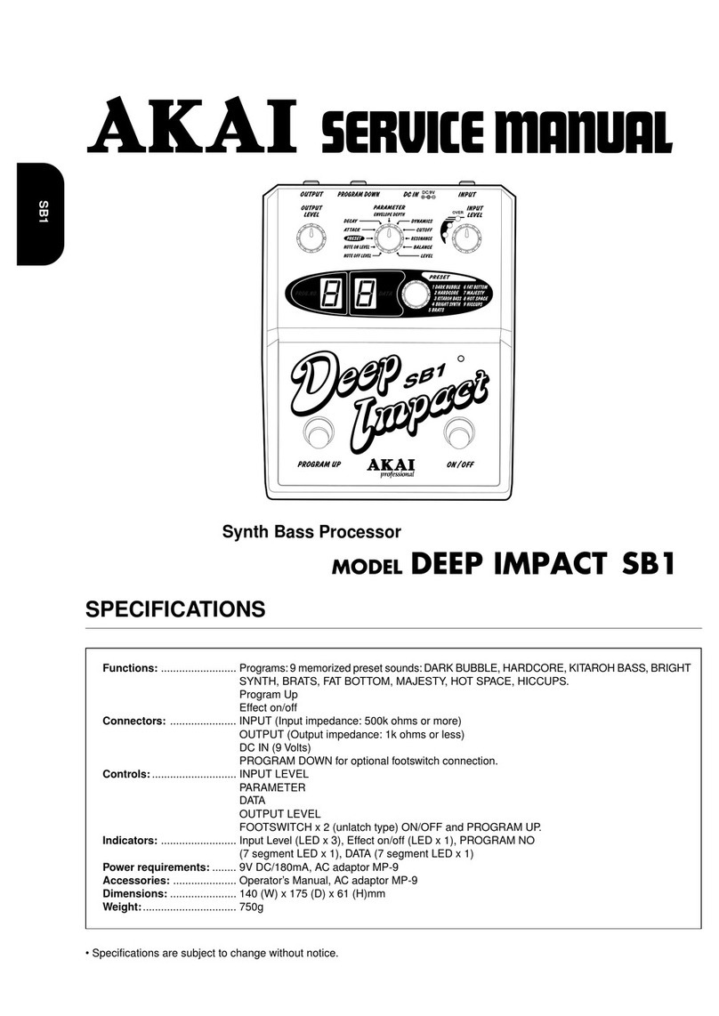
D2G
SPECIFICATIONS
EQUALIZED DISTORTION
MODEL G-DRIVE D2G
• Specifications are subject to change without notice.
OUTPUT INPUT
ON
OUTPUT
DRIVE
+50
0
-
50
+50
0
-
50
+50
0
-
50
+50
0
-
50
LOW HIGH
COLOR
LOW HIGH
CHARACTER
DC IN
DC 9V
ODERN BLUES
USION SOLO ILD FUZZADIO
S METAL RUNCH
M
MMM
M
M
M
M
M
M
M
M
C
C
CC
C
C
CC
C
C
CC
D
D
D
D
D
D
DD
DD
D
D
FF
F
F
FF
FF
F
F
F
F
R
R
R
RR
R
RRR
R
R
R
W
WW
WW
W
WW
W
W
W
W
M
FW
C
R
D
9
Functions: ......................... Effect On/Off
Connectors: ...................... INPUT (Input impedance: 300k ohms or more/Effect On, True Bypass/Effect Off)
OUTPUT (Output impedance: 1k ohms or less/Effect On,True Bypass/Effect Off)
DC IN (9 Volts)
Controls:............................ OUTPUT
DRIVE
COLOR x 6
CHARACTER x 6
Footswitch (Effect On/Off)
Indicators: ......................... LED (Effect ON)
Power requirements: ........ 9V DC/50mA 9V Manganese or Alkaline battery, AC adaptor MP-9 (optional)
Dimensions: ...................... 134 (W) x 175 (D) x 77 (H) mm
Weight:............................... 1,350g
Accessories: ..................... Operator’s Manual, Battery (9V)
Options: ............................. AC adaptor MP-9

SERVICE MANUAL
2
##
##
#SAFETY INSTRUCTIONS ##
##
#INFORMATIONS
1. Parts identified by the }symbol are critical for safety.
Replace them only with the parts number specified.
2. In addition to safety, other parts and assemblies are
specified for conformance with such regulations as those
applying to spurious radiation.
These must also be replaced only with the specified
replacements.
Examples : Noise blocking capacitors, noise blocking filters,
etc.
3. Use specified internal wiring. Note especially :
1) Wires covered with PVC tubing
2) Double insulated wires
3) High voltage leads
4. Use specified insulating materials for hazardous live parts.
Note especially :
1) Insulation Tape
2) PVC tubing
3) Spacers (insulating barriers)
4) Insulation sheets for transistors
5) Plastic screws for fixing micro switches
5. When replacing AC primary side components (trans-
formers, power cords, noise blocking capacitors, etc.), wrap
the ends of the wires securely around the terminals before
soldering.
6. Make sure that wires do not contact heat producing parts
(heat sinks, oxide metal film resistors, fusible resistors,
etc.).
7. Check that replaced wires do not contact sharp edged or
pointed parts.
8. Also check areas surrounding repaired locations.
9. Make sure that foreign objects (screws, solder droplets,
etc.) do not remain inside the set.
SAFETY CHECK AFTER SERVICING
After servicing, make measurements of leakage-current or
resistance in order to determine that exposed parts are
acceptably insulated from the supply circuit.The leakage-
current measurement should be done between accessible
metal parts (such as chassis, ground terminal, microphone
jacks,signal input/output connectors,etc.) and the earthground
through a resistor of 1500 ohms paralleled with a 0.15 µF
capacitor, under the unit’s normal working conditions.
The leakage-current should be less than 0.5 mA rms AC.The
resistance measurement should be done between accessible
exposed metal parts and power cord plug prongs with the
power switch (if included) “ON”. The resistance should be
more than 2.2 M ohms.
SYMBOLS FOR PRIMARY DESTINATION
Unit destinations are indicated with letters as shown below.
Symbols Principal Destinations
A U.S.A
B England
E Europe
J Japan
VGermany
X1 Japan
X4 Universal Area

3
D2G BLOCK DIAGRAM

REVISION
APPROVED CHECKED APPROVED DESIGNED
1st EDITION
A2File No.12345678
A
B
C
D
E
F
G
H
1234567891011
A
B
C
D
E
F
G
H
AKAI professional M. I. Corp.
PC MAIN, PC OPE.
L8016001
SCHEMATIC DIAGRAM
T.HIRANO
C1
10/50
R1
1M
R2
4.7K R3
1M
R103
4.7K
C101
3300P
R102
47K
R101
4.7K
C106
10/16
R5
47K
R104
1K
C102
10/16
C103
10/16
R105
1.5K
D102
1SS133
D101
1SS133
R106
10K R107
100K
C104
10/16
R108
4.7K
R109
4.7K
R110
4.7K
C105
1500P
2
3
1
J3
HTJ-020-05A
2
4
3
1
J1
HTJ-064-13H
2
4
3
1
J2
HTJ-064-13H
D141
L-934SRD-G
D2
1N4002
R6
100K
C3
0.01
C4
220/16
+9V
+9V
R7
100K
R8
100K
C5
10/50
+9V
VREF
C34
2200P
C33
0.027
C32
4700P
C31
0.047
C30
0.01
C29
0.1/50
C27
0.22/50
C28
0.018
C26
0.039
C25
0.47/50
C24
0.082
C23
1/50
R33
560
R34
47K
R32
47K
R31
560
R29
560
R27
560
R25
560
R23
560
R24
47K
R26
47K
R28
47K
R30
47K
1 3
2
VR126
20K
1 3
2
VR125
20K
1 3
2
VR124
20K
1 3
2
VR123
20K
1 3
2
VR122
20K
1 3
2
VR121
20K
3
21
84
IC16A
NJM4558L
3
21
84
IC15A
NJM4558L
3
21
84
IC14A
NJM4558L
7
5
6
IC15B
NJM4558L
7
5
6
IC14B
NJM4558L
7
5
6
IC16B
NJM4558L
3
21
84
IC102A
NJM4558L
75
6
IC102B
NJM4558L
7
5
6
IC101B
NJM4558L
3
21
84
IC101A
NJM4558L
7
5
6
IC1B
NJM4558L
3
21
84
IC1A
NJM4558L
VREF
VREF
VREF
VREF
VREF
VREF
+9V
+9V
+9V
C22
2200P
C21
0.027
C20
4700P
C19
0.047
C18
0.01
C17
0.1/50
C15
0.22/50
C16
0.018
C14
0.039
C13
0.47/50
C12
0.082
C11
1/50
R21
560
R22
47K
R20
47K
R19
560
R17
560
R15
560
R13
560
R11
560
R12
47K
R14
47K
R16
47K
R18
47K
1 3
2
VR116
20K
1 3
2
VR115
20K
1 3
2
VR114
20K
1 3
2
VR113
20K
1 3
2
VR112
20K
1 3
2
VR111
20K
3
21
84
IC13A
NJM4558L
3
21
84
IC12A
NJM4558L
3
21
84
IC11A
NJM4558L
7
5
6
IC12B
NJM4558L
7
5
6
IC11B
NJM4558L
7
5
6
IC13B
NJM4558L
VREF
VREF
VREF
VREF
VREF
VREF
+9V
+9V
+9V
1 3
5 4
2VR101
100K(B)
1 3
5 4
2
VR102
100K(A)
76
5
23
4
1 8
RL1
RY-9WK
SW901
SB-281
R4
1K
C2
10/50
GND.
D1
1SS133
C10
0.1
GND.
GND.
1
2
3
4
5
6
7
8
9
10
11
12
W101
WIRE ASSY L8016(1)12P
1
2
3
4
5
6
7
8
9
10
11
12
P1
S12B-PH-K
GND.VREF.
+9V.
+9V.
+9V.
GND.
GND.
VREF.
VREF
VREF.VREF
+9V
+9V
GND.
1
2
3
P101
S3B-PH-K
1
2
3
W901
WIRE ASSY L8016(2) 3P
GND.
R111
10K
R112
100K
C107
10/16
VREF.
R141
2.7K
+9V.
GND.
GND.
GND. GND.
EQIN1.
EQIN2.
EQIN3.
EQIN4.
EQIN5.
EQIN6.
EQOUT1.
EQOUT2.
EQOUT3.
EQOUT4.
EQOUT5.
EQOUT6.
EQIN1.
EQIN2.
EQIN3.
EQIN4.
EQIN5.
EQIN6.
EQOUT1.
EQOUT2.
EQOUT3.
EQOUT4.
EQOUT5.
EQOUT6.
1
2
3
4
5
6
W103
WIRE ASSY L8015(1)6P
1
2
3
4
5
6
P3
S6B-PH-K
EQIN1
EQIN2
EQIN3
EQIN4
EQIN5
EQIN6
EQOUT1
EQOUT2
EQOUT3
EQOUT4
EQOUT5
EQOUT6
EQIN1
EQIN2
EQIN3
EQIN4
EQIN5
EQIN6
EQOUT1
EQOUT2
EQOUT3
EQOUT4
EQOUT5
EQOUT6
006P
BATTERY
1
2
3
4
5
6
7
8
9
10
11
12
W102
WIRE ASSY L8016(1)12P
1
2
3
4
5
6
7
8
9
10
11
12
P2
S12B-PH-K GND.
GND.
L8016A501A
PC MAIN PC OPE.
L8016A501B
PC(#)D2G
D142
HZS6A2
C6
10/50
C108
470P
C109
0.015
C7
10/50
+9V
2000/12/08
C141
0.1
GND.
R113
1.8K
10K
TR101
DTC114TS
10K
10K
TR102
DTA114ES
GND.
C110
3.3/25
R114
10K
+9V.+9V.
NOTE : UNLESS OTHERWISE SPECIFIED
ALL RESISTORS IN OHMS 1/6W
ALL CAPACITORS IN uF. P=pF
ALL ERECTROLYTIC CAPACITORS IN uF/WV
WIRE ASSY MS-2-120-UL LEADWIRE
W902
R999
1K
R999
2000/12/08
H.TSUZUKI
INPUT
DC IN
INPUT EQ
INPUT EQ
OUTPUT EQ
LEVEL
GAIN
D2G
SCHEMATIC DIAGRAM
4

5

6

SERVICE MANUAL 7
PARTS LIST
HOW TO USE THIS PARTS LIST
1. This Parts List lists those parts which are considered necessary for repairs.
2. Parts not shown in the Parts List will not in principle be supplied.
3. How to read the Parts List.
WARNING
}}
}}
}INDICATES SAFETY CRITICAL COMPONENTS. FOR CONTINUED SAFETY, REPLACE SAFETY CRITICAL
COMPONENTS ONLY WITH MANUFACTURER'S RECOMMENDED PARTS.
AVERTISSEMENT
}}
}}
}IL INDIQUE LES COMPOSANTS CRITIQUES DE SÉCURITÉ. POUR MAINTENIR LE DEGRÉ DE SÉCURITÉDE
L'APPAREIL, NE REMPLACER QUE DES PIÉCES RECOMMANDEES PAR LÉ FABRICANT.
ATTENTION
1. When placing an order for parts, be sure to list the Part No., Model No. and the description of each part.
Otherwise, the non-delivery of the part or the delivery of a wrong part may result.
2. Please make sure that Part No. is correct when ordering.
If not, a part different from the one you ordered may be delivered.
3. Since the parts shown in Parts List or Preliminary Service Manual may have been the subject of changes,
please use this Parts List for all future reference.
1. PC MAIN BOARD BLK
Ref. No. Part No. Description
D5 ED-431276C D SCHOT 1S30-J T05
D110 ED-431276C D SCHOT 1S30-J T05
:
:
IC5 EI-811073J ICTRC-6593
IC10 EI-811068J IC HD74HC157FP
Service parts classification
These reference symbols correspond with component
symbols in the Schematic Diagrams.
2. FINAL ASSEMBLY BLK
Ref. No. Part No. Description
1. SA-349332 FOOT
2. ZS-344754C ST PAN30x06STL CMT
:
:
44. SP-417333J COVER TOP
45. ZS-418385J BT BID30X06STL BNI EATRH LOCK
46-A }EW-380905J AC CORD 250S KP300 KS16A
H B J [J]
46-B }EW-368420J1 AC CORD 200SKP30KS B AC [A]
46-C }EW-410608J AC CORD 250 KP4819D KS31A B E
[E,V]
Symbols for primary destination
[A] U.S.A. [J] Japan
[B] England [V] Germany
[E] Europe [x1] Japan
[X4] Universal Area
Safety critical component
This number corresponds with the individual parts index number
in the figure.

SERVICE MANUAL
8
1. PC BOARD BLK
The PC Board Block may contain several PC Boards.They appear
under its block name without their individual part number.If one of
thePCBoardisrequired,youneedtoorderthewholePCBoardblock.
The individual PC Board is not available separately.
Ref.No Part No. Description
1 BA-L8016A020A PC(#) D2G BLK D2G
# PC MAIN BLK
# PC OPERATION BLK
2. PC MAIN BLK
Ref.No Part No. Description
D2 ED-386225J D SILICON 1N4002 T26 100/1.0A
IC1 EI-403306J IC NJM4558L
IC11 EI-403306J IC NJM4558L
IC12 EI-403306J IC NJM4558L
IC13 EI-403306J IC NJM4558L
IC14 EI-403306J IC NJM4558L
IC15 EI-403306J IC NJM4558L
IC16 EI-403306J IC NJM4558L
J1 EJ-812069J PHONE J HTJ-064-13H 6.3
J2 EJ-812069J PHONE J HTJ-064-13H 6.3
J3 }EJ-812072J SOCKET DC HTJ-020-05A 1P
RL1 EQ-820421X RELAY SIG RY-9WK 1TR 9V
W902 EW-820443X WIRE ASSY MS-2-120-UL LEADWIRE
3. PC OPERATION BLK
Ref.No Part No. Description
100 SE-820494X SPACER LED L=7.0
D141 ED-812087J D LED L-934SRD-G RED
D142 ED-418682J D ZENER H HZS6A2 T26
IC101 EI-403306J C NJM4558L
IC102 EI-403306J C NJM4558L
TR101 ET-364492 TR DTC114TS T05
TR102 ET-366753 TR DTA114ES T05
VR101 EV-820415X VR ROTARY RK09L1141F20B15 B104
VR102 EV-820485X VR ROTARY RK09L1141F20A15 A104
VR111 EV-820444X VRSLIDE RS2511130615W24 W203S
VR112 EV-820444X VRSLIDE RS2511130615W24 W203S
VR113 EV-820444X VRSLIDE RS2511130615W24 W203S
VR114 EV-820444X VRSLIDE RS2511130615W24 W203S
VR115 EV-820444X VRSLIDE RS2511130615W24 W203S
VR116 EV-820444X VRSLIDE RS2511130615W24 W203S
VR121 EV-820444X VRSLIDE RS2511130615W24 W203S
VR122 EV-820444X VRSLIDE RS2511130615W24 W203S
VR123 EV-820444X VRSLIDE RS2511130615W24 W203S
VR124 EV-820444X VRSLIDE RS2511130615W24 W203S
VR125 EV-820444X VRSLIDE RS2511130615W24 W203S
VR126 EV-820444X VRSLIDE RS2511130615W24 W203S
4. FINAL ASSEMBLY BLK
Ref.No Part No. Description
1 SP-820403X PANEL TOP D2G
2 ZW-384700J1 PROP 2 F.SCREW L=10
3 ZS-355511 BID30X06STL BNI
4 ZS-418385J BT BID30X06STL BNI EARTH LOCK
5 SM-820407X MASK SLIDE
6 SH-820406X HANDLE
7 ZS-379405 BID30X06STL CMT
8 ZW-820401X PROP 6 M.SCREW L=20
9 ES-812047J SW PUSH SB-285(METAL) 02-02N
10 ZW-812439J SW120STL CMT
11 ZW-812440J PW122X160X050STL NI3
12 SC-820409X HOLDER BATTERY
13 ZS-820455X BT CTS30X06STL BNI
14 SP-820405X COVER BOTTOM D2G
15 SA-820495X FOOT K13W
16 ZS-820564X ST PAN30X10 STL BZN C080
17 SC-820412X COVER BATTRY
18 SE-820411X CUSHION BATTERY
19 ZS-820413X SCREW COSMETIC
20 ZW-820480X SLIT W25X060X050PSL
21 SK-820458X CAP(BLACK) 2.8X10X1.5
22 SK-820408X KNOB VOLUME

SERVICE MANUAL 9
FINAL ASSEMBLY BLK D2G
6
21
22
4
1
11
10
9
12
13 8
4
18
17 19
4
14
15
16
4
20
7
3
2
7
5
7

SERVICE MANUAL
10
1-3, Hiranuma 1-Chome, Nishi-Ku, Yokohama, Japan
SERVICE SECT. PHONE : +81-45-412-2373 FAX : +81-45-412-2372
Printed Date : Feb 15, 2001
Printed in Japan
ABBREVIATIONS FORTHE SERVICE MANUAL
ABBREVIATION EXPLANATION ABBREVIATION EXPLANATION
MINI MINImum
MIX MIXer
MOD MODulation / MODulator
M.WHEEL Modulation WHEEL
OSC OSCillator
PLD Programmable Logic Device
RAM Random Access Memory
RD ReaD
REG REGulator
RESO RESOnance
RL ReLay
ROM Read Only Memory
SCSI Small Computer System Interface
S/H Sample and Hold
SIMM Single Inline Memory Module
SMPTE Society of Motion Picture & Television
Engineers
SW SWitch
THRU THRoUgh
TRANS TRANSpose
U Upper
VA Voltage Analog
VCA Voltage Controlled Amplifier
VCF Voltage Controlled Filter
VR Variable Resistor
VREF REFerence Voltage
WR WRite
AMP (Amp) AMPlifier
BBD Backet Brigade Diode
BCD Binary Code Decimal
B.DOWN Brake DOWN
B.UP Back UP
CE Chip Enable
CH CHannel
COMP COMParator
CONT CONTrol
CV Control Voltage
D/A Digital to Analogue
DIR DIRectory
DMA Direct Memory Access
DSP Digital Signal Processor
EG Envelope Generator
EXT EXTernal
FREQ FREQuency
HPF High Pass Filter
INH INHibit
INT INTerrupt
INV INVerter
LLower
LAN Local Area Network
LFO Low Frequency Oscillator
MAX MAXimum
MEMO MEMOry
MIDI Musical Instrument Digital Interface
Other manuals for G-Drive D2G
1
Table of contents
Other Akai Recording Equipment manuals