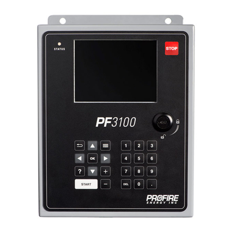
Profire Energy PF3100 Series User manual

PF3100 SOFTWARE SETUP GUIDE
A WALKTHROUGH FOR COMMISSIONING
V1.3
Revised Nov 29, 2016

PF3100 SOFTWARE SETUP GUIDE
©2016 Profire Energy Inc. –All rights reserved. No part of this publication
may be reproduced, distributed, or transmitted in any form without the prior
written permission of the publisher for reasons other than personal use
V1.3
Nov 29, 2016
Page 1
Table of Contents
1Setup overview ........................................................................................................................................................................................................... 2
1.1 Layout Overview............................................................................................................................................................................................. 2
1.1.1 System Overview ...................................................................................................................................................................................... 2
1.1.2 System Settings......................................................................................................................................................................................... 3
1.1.3 Appliance Screen ...................................................................................................................................................................................... 3
1.1.4 Appliance Settings .................................................................................................................................................................................... 3
1.2 Setup Tips........................................................................................................................................................................................................ 4
1.2.1 Multi-Controller Setup ............................................................................................................................................................................. 4
1.2.2 Quick PID Adjustment .............................................................................................................................................................................. 4
1.2.3 Setpoint Quick Adjust............................................................................................................................................................................... 5
2FIRMWARE UPDATE.................................................................................................................................................................................................... 6
3UI Settings.................................................................................................................................................................................................................... 7
4APPLIANCE CONFIGURATION..................................................................................................................................................................................... 8
4.1 Appliance wizard ............................................................................................................................................................................................ 8
5TEMPERATURE CONFIGURATION .............................................................................................................................................................................. 9
5.1 Temperature Wizard ...................................................................................................................................................................................... 9
6IGNITION CONFIGURATION...................................................................................................................................................................................... 11
6.1 Ignition wizard .............................................................................................................................................................................................. 11
7IO EXPANSION CONFIGURATION ............................................................................................................................................................................. 12
7.1 I/O Wizard..................................................................................................................................................................................................... 12
7.1.1 Adding Inputs:......................................................................................................................................................................................... 12
7.1.2 Allocating inputs to I/O modules:.......................................................................................................................................................... 13
7.1.3 PID Setup................................................................................................................................................................................................. 13
8Appliance & Controller settings ............................................................................................................................................................................... 15
8.1 Purge Time and Timing ................................................................................................................................................................................ 15
8.2 PID Setup for process control...................................................................................................................................................................... 15
8.3 Cold Start Ramping....................................................................................................................................................................................... 15
8.4 Proof of Closure............................................................................................................................................................................................ 16
8.5 Main permissive ........................................................................................................................................................................................... 16
8.6 Fuel Pressure Input....................................................................................................................................................................................... 16
8.7 Tank level input ............................................................................................................................................................................................ 17
8.8 Valve setup.................................................................................................................................................................................................... 17
8.9 Status contact Control ................................................................................................................................................................................. 18
8.10 Minimum controllers running ..................................................................................................................................................................... 18
8.11 System voltage.............................................................................................................................................................................................. 18
8.12 System restarts............................................................................................................................................................................................. 19
9Backup Settings ......................................................................................................................................................................................................... 20
10 Restore Settings ........................................................................................................................................................................................................ 21
11 Document Revision History...................................................................................................................................................................................... 22

PF3100 SOFTWARE SETUP GUIDE
©2016 Profire Energy Inc. –All rights reserved. No part of this publication
may be reproduced, distributed, or transmitted in any form without the prior
written permission of the publisher for reasons other than personal use
V1.3
Nov 29, 2016
Page 2
1Setup overview
The following document outlines key software items to configure for an initial system commissioning. It is
recommended to work through the software setup in the order shown below.
If the system has previously been commissioned, then it is recommended to backup settings before making any
changes or updating the firmware.
1.1 Layout Overview
1.1.1 System Overview
The system overview screen is the top level view of the user interface. It is the first screen that appears during
power up. This screen displays all appliances serviced from the user interface. From here you can access the
System Settings and each individual Appliance. In the image below the appliances are shown as Heater 1 and a
Combustor.

PF3100 SOFTWARE SETUP GUIDE
©2016 Profire Energy Inc. –All rights reserved. No part of this publication
may be reproduced, distributed, or transmitted in any form without the prior
written permission of the publisher for reasons other than personal use
V1.3
Nov 29, 2016
Page 3
1.1.2 System Settings
The system settings screen is accessed from the System overview screen. From here you can configure and access
the following items:
Item
Used for:
Appliance Wizard
Configuring appliances and allocating controllers to them.
Temperature Wizard
Configuring temperature inputs for process control including setpoints and allocating
temperature modules.
Ignition Wizard
Configuring ignition settings and allocating ignition modules.
I/O Wizard
Allocation of I/O Expansion Modules and configuration of settings.
Swap Wizard
A tool to assist with replacing hardware on site, such as temperature and ignition modules.
Reset to Defaults
A tool to reset the settings of controllers in appliances.
UI Settings
General configuration of UI Display settings, including Sleep timeout and units.
Settings Backup
A tool to backup configured settings to a USB drive.
Settings Restore
A tool to restore configuration settings from a USB drive.
Firmware Update
A tool to update the firmware of all connected modules in the system.
About Screen
Information on the firmware and build version of the system. This dialog also includes license
and copyright information.
1.1.3 Appliance Screen
This is the primary status screen for each appliance. It will display all key information such as process
temperatures, setpoints, control outputs such as firing rate and inputs such as tank level and fuel pressure.
The appliance settings are accessed from here.
1.1.4 Appliance Settings
The Appliance settings can be accessed from the Appliance screen. These are the primary configuration settings for
all controllers in the appliance and the appliance as a whole. Some of these settings are identical to ones found in
the temperature and ignition wizard and may be configured in either place.

PF3100 SOFTWARE SETUP GUIDE
©2016 Profire Energy Inc. –All rights reserved. No part of this publication
may be reproduced, distributed, or transmitted in any form without the prior
written permission of the publisher for reasons other than personal use
V1.3
Nov 29, 2016
Page 4
1.2 Setup Tips
1.2.1 Multi-Controller Setup
In many of the settings screens the multi-button can be used to open a dialog to independently adjust the setting
independently for each controller in the appliance.
When a setting is highlighted press the Multi-Button to open the Multi-Dialog. An example is shown below:
A. Link Settings is on. All of the settings are identical for all controllers in the appliance.
B. Link Settings is off. Settings may be individually adjusted for each controller.
1.2.2 Quick PID Adjustment
The BMS and I/O Expansion PID may be adjusted while the system is running for easy system tuning. They can be
accessed here:
The BMS PID is used for primary process control. The output is located on the BMS board.
The I/O expansion module PID operates only when the BMS is in a run state and can control any generic
peripherals for the system. The output is located on the I/O expansion board.

PF3100 SOFTWARE SETUP GUIDE
©2016 Profire Energy Inc. –All rights reserved. No part of this publication
may be reproduced, distributed, or transmitted in any form without the prior
written permission of the publisher for reasons other than personal use
V1.3
Nov 29, 2016
Page 5
1.2.3 Setpoint Quick Adjust
From the System Overview or Appliance screen the primary process temperature may be adjusted in small
increments. Press the Multi-Button when on one of these screens to open up the quick adjust dialog as shown
below.
In this example we increased the process setpoint by 2.0 F. All other setpoints scale together, but are limited on
the top end by the High Temp Setpoint and on the low end by the Low Temp SP.

PF3100 SOFTWARE SETUP GUIDE
©2016 Profire Energy Inc. –All rights reserved. No part of this publication
may be reproduced, distributed, or transmitted in any form without the prior
written permission of the publisher for reasons other than personal use
V1.3
Nov 29, 2016
Page 6
2FIRMWARE UPDATE
Anytime a system is first commissioned or a new/replacement module is added a firmware update should be
performed. The user interface, all controllers and modules must have the same firmware bundle in order for them
to communicate.
A copy of the firmware required for your system can be provided by Profire.
1. Copy the firmware bundle onto a USB stick.
2. Place the USB stick into the PF3100 User Interface (USB port is located inside the enclosure on the UI
card).
3. Open the Update Firmware Dialog:
4. Select the firmware bundle from the Dialog.
5. Wait for all hardware to show up on the connected modules screen.
6. After all hardware has shown up, select Accept to begin the firmware update process.
7. When complete the Update report will show all of the successfully updated targets (shown in green). If
some targets fail to update (shown in red) re-run the firmware update process.
8. The user interface will automatically firmware update after the modules have been updated.
9. Restore the settings from before the firmware update or re-commission the system.
10. A power cycle is recommended after the firmware update process.

PF3100 SOFTWARE SETUP GUIDE
©2016 Profire Energy Inc. –All rights reserved. No part of this publication
may be reproduced, distributed, or transmitted in any form without the prior
written permission of the publisher for reasons other than personal use
V1.3
Nov 29, 2016
Page 7
3UI Settings
Set the following to the preferred units.
Setting
Used for:
Temperature units
All system temperatures, including process temperature and PID control.
Pressure units
Used for fuel pressure input.
Volume units
Used for level input.

PF3100 SOFTWARE SETUP GUIDE
©2016 Profire Energy Inc. –All rights reserved. No part of this publication
may be reproduced, distributed, or transmitted in any form without the prior
written permission of the publisher for reasons other than personal use
V1.3
Nov 29, 2016
Page 8
4APPLIANCE CONFIGURATION
4.1 Appliance wizard
The appliance wizard allows you to create and modify appliances in the system.
1. Start by adding an appliance and naming it appropriately.
2. More than one appliance may be added to match the application.
3. Assign the controllers used for the appliance to the appliance by selecting the controller.
4. Name the controller after what it will be used for or where it will be located. For example: “East Burner”,
“West Burner”, “Burner 1”.
5. In the review tab, apply the changes to save them.

PF3100 SOFTWARE SETUP GUIDE
©2016 Profire Energy Inc. –All rights reserved. No part of this publication
may be reproduced, distributed, or transmitted in any form without the prior
written permission of the publisher for reasons other than personal use
V1.3
Nov 29, 2016
Page 9
5TEMPERATURE CONFIGURATION
5.1 Temperature Wizard
The temperature wizard allows you to set up and allocate different temperature inputs for the system.
1. Start by selecting the Appliance you would like to configure. Only one appliance can be configured at a
time.
2. A primary process must always be configured in order for the system to operate. Additional inputs may be
added as needed. A description of the input types is provided below.
3. Make sure to uniquely name the temperature inputs. This can be done by selecting the temperature input
name, a keyboard will pop up to edit the data.
4. Change the appliance shutdown for the input according to the needs of the application. An input with the
shutdown enabled will prompt an appliance level alarm if lost from a controller.
5. The input can be selected as a single or dual input. This should match the type of thermocouple
connection used.
6. Under the assign inputs tab, the temperature inputs previously created may now be allocated to the
installed temperature module hardware. It’s important to have the temperature modules plugged in and
communicating or else they will not show up in the wizard. If you are missing a module from the list –
check its PFRN connection.
7. Match up the temperature module hardware inputs to the temperatures connected to them. Each
module has a MAC address on it, this is shown in the temperature wizard to identify the unit.
8. The setpoints may now be adjusted for the application.
9. Low fire must be enabled if using PID control.
Temperature input configuration
Settings
Function
Name
A unique identifier for each temperature input.
Mode
Primary Process
This is the minimum temperature input required for the system to operate.
Temperature will be satisfied if the primary setpoint is achieved. Often this
will be something like tank temperature.
Aux Process
The input is used as an additional secondary process. This is controlled in
conjunction with the primary process. Temperature will be satisfied if the
primary setpoint or secondary process setpoint is achieved. Often this will
be something like outlet temperature.
High Temp ESD
The input is used as a high temperature shutdown only. Often this will be
something like stack temperature.
Display Only
The temperature will only be displayed; it has no effect on system
operation.
Disabled
The input may be disabled if it is temporarily not required or if a
temperature module is undergoing service.
Appliance Shutdown
Enabled
Disabled
Input Type
Single
Only one thermocouple or RTD input is used.

PF3100 SOFTWARE SETUP GUIDE
©2016 Profire Energy Inc. –All rights reserved. No part of this publication
may be reproduced, distributed, or transmitted in any form without the prior
written permission of the publisher for reasons other than personal use
V1.3
Nov 29, 2016
Page 10
Dual
Two thermocouple inputs are used. They must match or else the system
will alarm.
Temperature setpoints
Settings
Function
High temp setpoint
The system will shutdown if this temperature is reached.
Process temp setpoint
The system will attempt to maintain this temperature.
Pilot off mode
Disabled
The pilot will stay on at all times.
Off at setpoint
The pilot will turn off after the pilot off setpoint is achieved.
Off After main proven
The pilot will turn off after the main is detected.
Follow Main
The pilot will turn on when the main is on, and off when the main is
off.
Pilot off setpoint
The temperature where the pilot will turn off if set to “Pilot off at
setpoint” mode.
Low fire mode
Disabled
Low fire is disabled. System will go directly to high fire.
On at process setpoint
Low fire will turn on as the process temperature drops back down
to the process setpoint. Low fire will turn off at the low fire
setpoint.
On at low fire setpoint
Low fire will turn on as the process temperature drops below the
low fire setpoint. Low fire will turn off at the low fire setpoint.
Low fire setpoint
Used for low fire control. Disabled when low fire is disabled.
Low temp setpoint
Used for a low temperature warning. May be routed to the status
output.
** Note: Low fire must be enabled (either at process or low fire) if BMS PID control will be used.

PF3100 SOFTWARE SETUP GUIDE
©2016 Profire Energy Inc. –All rights reserved. No part of this publication
may be reproduced, distributed, or transmitted in any form without the prior
written permission of the publisher for reasons other than personal use
V1.3
Nov 29, 2016
Page 11
6IGNITION CONFIGURATION
6.1 Ignition wizard
The ignition wizard allows you to configure ignition modules and specify the appliance ignition settings.
1. Start by selecting the Appliance you would like to configure. Only one appliance can be configured at a
time.
2. Up to 4 ignition modules can be configured for each controller in an appliance. Select one of the slots to
add an ignition module to it.
3. By selecting the MAC Address setting a popup will appear listing all available ignition modules connected
to the controller. Select one of the modules to add it in this slot.
4. Enable the slot before exiting the selection screen.
5. Enable main flame detection if required.
6. Set the minimum number of pilots running accordingly for the application. If the system fails to ignite the
minimum require number of pilots the system will shutdown.
Ignition Settings
Settings
Function
Main Flame Detect
Enable or disable main flame detection if used.
Ignition Mode
An ignition coil (standard) or an external high intensity ignition
module may be used for sparking. Set the mode according to the
type of device used.
Relight Attempts
This is the number of times the system will attempt to relight if the
pilot flame fails.
Minimum Pilot Running
This is the minimum number of pilots that are required to be
running (detecting flame) for the system to continue running. The
system will shutdown if the minimum number of pilots is exceeded.
Pilot Relight Mode
No Relight
For multi-pilot applications –If the pilot flame fails, the pilot will
remain off until the system is restarted.
During Flame Fail
For multi-pilot applications –As soon as the pilot flame fails the
pilot will spark and attempt to quickly relight for a maximum of 4
seconds.
During Timeout
For multi-pilot applications –As soon as the pilot flame fails the
pilot will spark and attempt to relight for the amount of time
specified by the Pilot Timeout Time.
Pilot Timeout Time
For multi-pilot applications –For use with the “During Timeout”
Pilot Relight mode.

PF3100 SOFTWARE SETUP GUIDE
©2016 Profire Energy Inc. –All rights reserved. No part of this publication
may be reproduced, distributed, or transmitted in any form without the prior
written permission of the publisher for reasons other than personal use
V1.3
Nov 29, 2016
Page 12
7IO EXPANSION CONFIGURATION
7.1 I/O Wizard
The I/O wizard allows you to configure inputs and outputs for use with the IO expansion module. This includes
supplementary PID control.
7.1.1 Adding Inputs:
1. Select the Input type: When you add an input you will be prompted to select the input type. The input
type changes how the data is displayed and interpreted throughout the UI. The following are available:
Input Type
Available Units
Pressure
kPa, PSI, inWC, cmWC, kg/cm2
Flow
m3/s, Liters, USGAL, BBL, ft3 in time intervals of seconds, minutes, hours and days.
Level
Liters, m3, USGAL, BBL, kg/cm2
Custom
Generic units in %
Appliance Firing Rate
Firing rate in %
2. Select the Signal Type: In most cases the input can be configured as a 4-20mA or digital input. When
configured as an appliance firing rate the input will always operate in 4-20mA mode.
Input Type
Available Units
Digital
The input is either ON or OFF depending on the logic of the input signal. Digital inputs do
not have setpoints.
4-20mA
Configured as an analog current source input with a range between 4 to 20mA.
3. Select the Input Mode: The effect the input has on the system is determined by the input mode. The
following are available.
Input Mode
Description
Alarm
Will set an alarm if the input signal is out of the setpoint range (4-20mA) or open (digital).
Wait
Will place the system into a wait state if the input signal is out of the setpoint range (4-
20mA) or open (digital).
Warning
Will set a warning if the input signal is out of the setpoint range (4-20mA) or open (digital).
Main Permissive
Will allow the system to enter high fire state if the input signal is within the setpoint range
(4-20mA) or closed (digital).
Check After Main * (Not yet
available)
These inputs are checked after the system enters a high fire state. If they are not satisfied
the system will alarm. The system will alarm if out of the setpoint range (4-20mA) or is
open (digital).
Proof of Airflow * (Not yet
available)
Airflow must be proven in order to satisfy purging. If the input is within the setpoint range
(4-20mA) or it is closed (digital), purging will be proven.
Appliance Firing Rate
The appliance firing rate is now taken from this input in a range of 0 to 100%.
4. Input Settings: Each input has the following settings to configure:

PF3100 SOFTWARE SETUP GUIDE
©2016 Profire Energy Inc. –All rights reserved. No part of this publication
may be reproduced, distributed, or transmitted in any form without the prior
written permission of the publisher for reasons other than personal use
V1.3
Nov 29, 2016
Page 13
Setting
Description
Name
Select a unique and descriptive name for the input. This name will be used throughout the
system to identify the input.
Units
Select the appropriate units for the application.
Low Setpoint
This is the low trip point for the input.
High Setpoint
This is the high trip point for the input.
Deadband
The deadband is applied to the low and high trip point for hysteresis of the signal.
7.1.2 Allocating inputs to I/O modules:
I/O cards that are currently connected to the system will be displayed in the I/O Cards tab. The inputs previously
created may now be added to the physical card. Outputs and contacts may also be configured in this screen.
1. Add inputs: To add a previously created input, open the one of the available inputs and select it from the
list.
2. Configure Input: If the input is a transmitter (4-20mA) the span will need to be configured. Enter the
transmitters 4mA value (span low) and the transmitters 20mA value (span high).
3. 4-20mA Output: The 4-20mA output can be controlled by different sources. Open the 4-20mA output
dialog and select the source appropriate for the application. The PID configuration is outlined in the PID
Setup section below.
a. PID Output Controlled by 4-20mA Input: This will route the control of the output from a PID that
is controlled by another 4-20mA input.
b. PID Output Controlled by TC/RTD Input: This will route the control of the output from a PID that
is controlled by a system temperature input.
4. Dry Contact Configuration: Each contact may be configured with a different mode of operation as
follows:
Dry Contact Mode
Description
Disabled
Contact is always de-energized.
Started Status
Energized when system is started.
High Temp Status
Energize when high temp shutdown is triggered.
No Alert Status
Energized when the system has no alerts.
Process Control
Energized when the minimum controllers running or more are in a process control
state such as High Fire.
5. Module voltage: The IO expansion board may be configured for 12 or 24V operation. This is the board
output voltage for sensors and the 4-20mA output. It has no effect on the inputs to the system.
6. Review and accept the changes when complete.
7.1.3 PID Setup
The following configuration parameters are available when setting up the PID for use with the 4-20mA output on
the IO module.

PF3100 SOFTWARE SETUP GUIDE
©2016 Profire Energy Inc. –All rights reserved. No part of this publication
may be reproduced, distributed, or transmitted in any form without the prior
written permission of the publisher for reasons other than personal use
V1.3
Nov 29, 2016
Page 14
Setting
Description
Setpoint
This is the setpoint that the PID attempts to obtain during operation.
Proportional Band
See the PID tuning guide.
Integral Time
Derivative Time
Integral Reset Range
Direction
This is the control direction of the PID.
Direct –The PID will increase its output in response to an increasing input.
Reverse –The PID will increase its output in response to a decreasing input.
Mode
Auto –The system operates in PID mode.
Manual –The system sets the output to a static output according to the Manual Output
value.
Manual Output
The output value when in Manual mode. Not used in Auto mode.
System Stop Output
When the BMS is stopped or not running the 4-20mA output will be set to this position.
Low Output Limit
When the PID is running this is the minimum value that the system will output.
High Output Limit
When the PID is running this is the maximum value that the system will output.

PF3100 SOFTWARE SETUP GUIDE
©2016 Profire Energy Inc. –All rights reserved. No part of this publication
may be reproduced, distributed, or transmitted in any form without the prior
written permission of the publisher for reasons other than personal use
V1.3
Nov 29, 2016
Page 15
8Appliance & Controller settings
8.1 Purge Time and Timing
Set up the purge time according to the appliance requirements.
1. Purge Time - The minimum time the system will purge for.
2. Pilot to Main Delay –The amount of time the system will delay when transitioning between pilot and
main.
3. Low to high fire delay –The amount of time the system will delay when transitioning between low fire
and high fire.
8.2 PID Setup for process control
1. Make sure that low fire is enabled:
a.
b. Set the low fire mode to either On at Process Setpoint or On at Low Fire Setpoint.
c. Set the low fire setpoint for the system.
2. Enable the proportional valve output:
a.
b. Set the 4-20 Aux Out Mode to PID Control
c. Set the Purge Position –this is the valve position when the system is in the purge state.
d. Set the Pilot Position –this is the valve position when the system is in the pilot state.
e. Set the TCV PID Min Opening –this is the minimum position the valve will close to when
operating from the PID.
3. Configure the PID:
a.
b. The PID settings will need to be configured individually and tested for each application. Review to
the PID tuning guide for information on how the PID works and best tuning practices.
8.3 Cold Start Ramping
Cold start ramping can be used to control the rate of warmup for the appliance by regulating the allowable
temperature rise over a specific amount of time.
1. Enable the feature with the Temp Ramp setting.
2. Set the temperature Step Size –this is the maximum temperature rise (change in temperature) allowed
during the Time Step Size.
3. Set the Time Step Size appropriately for the desired rate of change.

PF3100 SOFTWARE SETUP GUIDE
©2016 Profire Energy Inc. –All rights reserved. No part of this publication
may be reproduced, distributed, or transmitted in any form without the prior
written permission of the publisher for reasons other than personal use
V1.3
Nov 29, 2016
Page 16
For example, if you would like the appliance to heat up a maximum of 30 C over the course of one hour the
following settings would be acceptable:
Result
Temp Step Size
Time Step Size
Coarse ramp
30 C
60 min
Fine ramp
10 C
20 min
8.4 Proof of Closure
There are two inputs that may be used for proof of closure as follows:
1. Set the proof of closure to enabled.
2. This setting uses the POC input on the BMS controller and should be connected to the SSV’s.
1. Set the mode to the desired operating type depending on the application: Proof of Low Fire, Proof of
Closure 2, Proof of Pilot.
2. This setting uses the AUX in contact on the BMS controller and should be connected as required by the
setting.
8.5 Main permissive
If main permissive is enable, the input must be satisfied in order for the system to enter main, other wise the
system will remain in a waiting state.
1. Enable the main permissive input for the Aux In Contact.
2. Set the Main Permissive Masking to “All Inputs” for the system to go to a waiting state with the pilot still
active.
3. Set the Main Permissive Masking to “No Inputs” for the system to go to a waiting state with all valves
closed.
8.6 Fuel Pressure Input
The fuel pressure input on the BMS can be configured as follows:
1. Set the fuel pressure input mode according the type of fuel pressor sensor or switch used.
a. Dry contact –pressure switch with ON/OFF operation.
b. 4-20 Input –pressure transmitter with 4-20mA operation.
c. Dry Contact High Press. –pressure switch with ON/OFF operation for high pressure shutdown.
2. Low Fuel Pressure restart –If the system shuts down due to low fuel pressure it will attempt to restart.
3. When a pressure transmitter is used the following settings must be configured:

PF3100 SOFTWARE SETUP GUIDE
©2016 Profire Energy Inc. –All rights reserved. No part of this publication
may be reproduced, distributed, or transmitted in any form without the prior
written permission of the publisher for reasons other than personal use
V1.3
Nov 29, 2016
Page 17
a. 4-20 Fuel Pressure Max –The pressure output of the transmitter at 20mA.
b. 4-20 High Fuel Pressure SP –High fuel pressure trip point.
c. 4-20 Low Fuel Pressure SP –Low fuel pressure trip point.
d. Fuel pressure dead band –trip point deadband.
e. Low Fuel Pressure Delay –amount of time the fuel pressure needs to be below the low fuel
pressure setpoint in order for it to trip.
8.7 Tank level input
The tank level input on the BMS can be setup as follows:
1. Set the Tank level input mode to the type of switch or sensor used.
a. Dry Contact –Level switch with ON/OFF operation.
b. 4-20 Input –Level sensor with 4-20mA operation.
2. Set the Local Level Input according to the sensor location and if it’s shared with other controllers. This
setting allows for a single level sensor to be shared with more than one controller.
a. Set to Disabled if the input information is being received from another controller in the
appliance. This means that a level sensor or switch is not physically connected to the controller
being currently commissioned.
b. Set to Enabled if the controller has a level sensor connected to its input. This controller will now
broadcast the level information to other controllers in the appliance.
3. When a level sensor is used the following settings must be configured:
a. 4-20 Tank Level Max –The level output of the transmitter at 20 mA.
b. 4-20 Tank Level Min –The level output of the transmitter at 4 mA.
c. 4-20 High Tank Level SP –The high level trip point.
d. 4-20Low Tank Level SP –The low level trip point.
e. Tank Level deadband –trip point deadband.
f. Low Tank Level Delay –amount of time the level needs to be below the fuel pressure setpoint in
order for it to trip.
g. Appliance Level Tolerance –The allowable tolerance between multiple level sensors across the
appliance. If the tolerance is exceeded the system will alarm.
8.8 Valve setup
The valve duty cycle may be adjusted for different applications and valve requirements. These settings can be
found here:
Set the valve output % according to the requirements of the install.

PF3100 SOFTWARE SETUP GUIDE
©2016 Profire Energy Inc. –All rights reserved. No part of this publication
may be reproduced, distributed, or transmitted in any form without the prior
written permission of the publisher for reasons other than personal use
V1.3
Nov 29, 2016
Page 18
8.9 Status contact Control
The status contact output has different mode of operation that may be configured as follows:
Status Mode
Closed when:
Run Status
The system is in one of the following states:
Waiting, Startup, Igniting, Pilot, LowFire, HighFire
Run & Start Status
The system is in one of the following states:
Igniting, Pilot, LowFire, HighFire
Heating Status
The system is in one of the following states:
Igniting, Pilot, LowFire, HighFire
Pilot Flame Monitor
Flame quality > 50% and is in one of the following states: Waiting, Startup, Igniting, Pilot,
LowFire, HighFire
Low Temp Warning
Process temp is below the Low Temp Setpoint and the system is in one of the following states:
Waiting, Startup, Igniting, Pilot, LowFire, HighFire
High Tank Level
The tank level is below the high level setpoint and the system is in one of the following states:
Waiting, Startup, Igniting, Pilot, LowFire, HighFire
Low Temp Warning requires the Low temp setpoint to be configured here:
High Tank Level requires the high level setpoint to be configured here:
8.10 Minimum controllers running
If there is a requirement to have a certain number of controllers running in the appliance it can be set here:
The minimum number of controllers running must be less than or equal to the appliance size.
If there is less than the minimum number of controllers running, then the system will alarm and shutdown.
8.11 System voltage
Set the system voltage according to the install requirements:

PF3100 SOFTWARE SETUP GUIDE
©2016 Profire Energy Inc. –All rights reserved. No part of this publication
may be reproduced, distributed, or transmitted in any form without the prior
written permission of the publisher for reasons other than personal use
V1.3
Nov 29, 2016
Page 19
8.12 System restarts
The following system auto-restarts may be enabled:
Low and high voltage restart:
1. Low voltage restart –The system will shutdown if the voltage becomes too low or power to the system is
lost. Upon recovery of the power source the system will restart automatically.
2. High voltage restart –The system will shutdown if the voltage becomes too high. Upon recover of the
correct voltage the system will restart automatically.
Communication loss restart
The system will shutdown if communication is lost to any of the modules. When communication returns the
system will restart automatically.
Other manuals for PF3100 Series
5
Table of contents
Other Profire Energy Controllers manuals

