e
r
t
y
u
i
q
w
o
!0
!1
!2
!5
!6
!7
!8
!9
@0
!3 !4
e
r
t
y
u
@1
i
q
w
o
!0
!1
!2
!5
!6
!7
!8
!9
@0
!3 !4
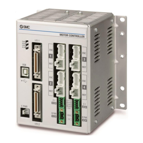
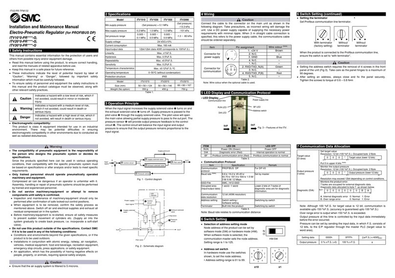
Controller Details
Parallel I/O JXC73/83
EtherNet/IPTM Type JXC93
No. Name Description Details
qPWR Power supply LED (Green)
Power supply ON: Green turns on. Power supply OFF: Green turns off.
wRUN Operation LED (Green)
Running in EtherNet/IP
TM
: Green turns on. Running via USB
communication: Green flashes. Stopped: Green turns off.
eUSB USB connection LED (Green)
USB connected: Green turns on. USB not connected: Green turns off.
rALM Alarm LED (Red)
With alarm: Red turns on. Without alarm: Red turns off.
tUSB Serial communication Connect to a PC via the USB cable.
yC PWR
Main control power supply connector (2 pins)
∗1Main control power supply (+) (−)
u
x100
x10
x1
IP address setting switches Switch to set the 4th byte of the IP address by X1,
X10 and X100.
iMS, NS Communication status LED
Display the status of the EtherNet/IP
TM
communication.
oENC zEncoder connector (16 pins) Axis 1: Connect the actuator cable.
!0 MOT zMotor power connector (6 pins)
!1 ENC xEncoder connector (16 pins) Axis 2: Connect the actuator cable.
!2 MOT xMotor power connector (6 pins)
!3 CI zx Motor control power supply
connector ∗1
Motor control power supply (+), Axis 1 stop (+), Axis 1
lock release (+), Axis 2 stop (+), Axis 2 lock release (+)
!4 M PWR zx
Motor power supply connector
∗1
For Axis 1, 2. Motor power supply (+), Common (−)
!5 ENC cEncoder connector (16 pins) Axis 3: Connect the actuator cable.
!6 MOT cMotor power connector (6 pins)
!7 ENC vEncoder connector (16 pins) Axis 4: Connect the actuator cable.
!8 MOT vMotor power connector (6 pins)
!9 CI cv Motor control power supply
connector ∗1
Motor control power supply (+), Axis 3 stop (+), Axis 3
lock release (+), Axis 4 stop (+), Axis 4 lock release (+)
@0 M PWR cv
Motor power supply connector
∗1
For Axis 3, 4. Motor power supply (+), Common (−)
@1 P1, P2
EtherNet/IP
TM
communication connector
Connect Ethernet cable.
∗1: Connectors are included. (Refer to page 9.)
No. Name Description Details
qPWR Power supply LED (Green)
Power supply ON: Green turns on. Power supply OFF: Green turns off.
wRUN Operation LED (Green)
Running in parallel I/O: Green turns on. Running via USB
communication: Green flashes. Stopped: Green turns off.
eUSB USB connection LED (Green)
USB connected: Green turns on. USB not connected: Green turns off.
rALM Alarm LED (Red)
With alarm: Red turns on. Without alarm: Red turns off.
tUSB Serial communication Connect to a PC via the USB cable.
yC PWR
Main control power supply connector (2 pins)
∗1Main control power supply (+) (−)
uI/O 1 Parallel I/O connector (40 pins) Connect to a PLC via the I/O cable.
iI/O 2 Parallel I/O connector (40 pins) Connect to a PLC via the I/O cable.
oENC zEncoder connector (16 pins) Axis 1: Connect the actuator cable.
!0 MOT zMotor power connector (6 pins)
!1 ENC xEncoder connector (16 pins) Axis 2: Connect the actuator cable.
!2 MOT xMotor power connector (6 pins)
!3 CI zx Motor control power supply
connector ∗1
Motor control power supply (+), Axis 1 stop (+), Axis 1
lock release (+), Axis 2 stop (+), Axis 2 lock release (+)
!4 M PWR zx
Motor power supply connector
∗1
For Axis 1, 2. Motor power supply (+), Common (−)
!5 ENC cEncoder connector (16 pins) Axis 3: Connect the actuator cable.
!6 MOT c
Motor power connector (6 pins)
!7 ENC vEncoder connector (16 pins) Axis 4: Connect the actuator cable.
!8 MOT v
Motor power connector (6 pins)
!9 CI cv Motor control power supply
connector ∗1
Motor control power supply (+), Axis 3 stop (+), Axis 3
lock release (+), Axis 4 stop (+), Axis 4 lock release (+)
@0 M PWR cv
Motor power supply connector
∗1
For Axis 3, 4. Motor power supply (+), Common (−)
∗1: Connectors are included. (Refer to page 9.)
4 Axis Step Motor Controller JXC73/83/93 Series
