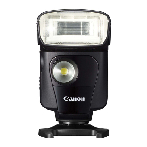
Profoto A1 User manual

Forotherlanguagesvisit:
www.profoto.com
User guide
ProfotoA1

A1 AirTTL
2
www.profoto.com

A1 AirTTL
3
www.profoto.com
Congratulations on your new
Profoto product!
Regardless ifyou chose a newflash or a new light shaping tool,know
thatalmosthalfacentury’sworthofexperiencewasputintoitsmaking.
If the years have taught us one thing, it is to never neglect a single
detail.We only put ourname on a product in whichwe have the fullest
confidence. Before shipping, every one of our products passes an
extensive and strict testing program. Unless it complies with the
specified performance,qualityand safety,it is a no-go.
As a result, we are confident that your new Profoto product will stay
withyouforyearsand helpyougrowasaphotographer. Butgettingthe
productisonlythe beginningofthatjourney. Usingitforlightshapingis
therealadventure.Thatiswhywetakeprideinprovidingyouwithsuch
awideassortmentoflightshapingtools,allowingyoutoshape thelight
in anywayyou can imagine.
The almost infinite possibilities might seem bewildering at first, but
we’re certain you will soon get the hang ofit.
I encourage you to sign up for our newsletter or visit Profoto stories,
www.profoto.com/profoto-stories, to learn more about shaping
light from photographers who are sharing their stories about how
Profoto Light ShapingTools help them to create outstanding images.
Enjoyyour Profoto product!
ConnyDufgran,founder

A1 AirTTL
4
www.profoto.com
General safety instructions
Safety Precautions!
Do not operate the equipment before studying the instruction manual and the accompanying safety.
Make sure that Profoto Safety Instructions is always accompanied the equipment! Profoto products
are intended for indoor conditions use.Do not place oruse the equipment where it can be exposed to
moisture,extreme electromagnetic fields,orin areaswith flammable gases or dust! Do not expose the
equipmenttodripping or splashing.Donot place anyobjectsfilledwithliquids,suchasvases,onornear
theequipment.Donotexposetheequipmentto hastytemperaturechanges inhumid conditionsasthis
could lead to condensation water in the unit.Do not connect this equipment to flash equipmentfrom
other brands.Front lens shall be changed if it has become visiblydamaged to such an extent that their
effectivenessisimpaired,forexamplebycracksordeep scratches. Equipmentmustonly beserviced,
modified or repaired by authorized and competent service personnel
WARNING – Electrical Shock Hazard – High Voltage!
Donot openordisassemble flashes,generatorsorlamp heads! Equipmentoperateswithhighvoltage.
Generatorcapacitors are electrically charged for a considerable length of time after being turned off.
Batteries (battery pack or batteries installed) shall not be exposed to excessive heat such as direct
sunlight,fire, orthe like.
Caution – Burn Hazard – Hot Parts!
If front lens cracks,it must be replaced before re-use of the equipment.Do not touchfront lens during
operation it mayreach high temperature.
Note about RF!
This equipment makes use of the radio spectrum and emits radio frequency energy. Proper care
should be taken when the device is integrated in systems.Make sure that all specifications within this
documentarefollowed,especiallythose concerningoperating temperatureandsupplyvoltagerange.
Make sure the device is operated according to local regulations.The frequencyspectrum this device
is using is shared with otherusers.Interference cannot be ruled out.
Laser radiation
IEC 60825-1,Edition 2.0 (2007-03).Wavelength at room temperature: 660 nm.Power through 7 mm
apertureat100mm distanceinfrontoftheexitwindowoftheautofocusassistunit atroomtemperature:
< 300 µW. Complies with 21 CFR 1040.10 and 1040.11 except fordeviations pursuant to Laser Notice
No.50,date June 24,2007.
Caution: Do not remove,disassemble or manipulate the laserauto focus assist light. Failure to comply
with this caution might lead to possible exposure to hazardous laser radiation.
Final Disposal
Equipment contains electrical and electronic components that could be harmful to the environment.
Equipment may be returned to Profoto distributors free of charge for recycling according to WEEE.
Followlocallegalrequirementsforseparatedisposalofwaste,forinstanceWEEEdirectiveforelectrical
and electronic equipment on the European market,when product life has ended!
CLASS 1
LASER PRODUCT

A1 AirTTL
5
www.profoto.com
Table of Contents
General safety instructions.............................................................................................4
Introduction .........................................................................................................................6
About the product............................................................................................6
Getting started.................................................................................................................. 10
Battery charging............................................................................................. 10
Attach battery to flash....................................................................................11
Attach light shaping tools.............................................................................11
On-camera use in TTL mode ......................................................................12
On-camera use in manual mode ...............................................................12
O-camera use............................................................................................... 13
Operation.............................................................................................................................14
Power on/o.....................................................................................................14
Mode selection (TTL or Manual) ................................................................14
Energy scale .................................................................................................... 15
Operation in TTL mode (Automatic mode) ........................................... 15
Operation in MAN mode (Manual mode)................................................17
Modeling light ................................................................................................. 18
Activate/deactivate flash head ................................................................ 19
Manual zoom................................................................................................... 19
Test sync..........................................................................................................20
Using the flash o-camera ........................................................................ 20
Change settings............................................................................................20
General notes on Profoto Air operation................................................................... 26
Light shaping.................................................................................................................... 28
Dome Diuser................................................................................................ 29
Bounce Card...................................................................................................30
Wide Lens......................................................................................................... 31
Additional functions....................................................................................................... 33
Firmware upgrade......................................................................................... 33
Factory reset................................................................................................... 33
Profoto Air compatibility .............................................................................................. 34
Technical data.................................................................................................................. 35
Warranty..............................................................................................................................37
Regulatory information ................................................................................................. 38

A1 AirTTL
6
www.profoto.com
Introduction
Abouttheproduct
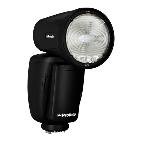
We have designed theA1 to be the world’s smallest studio light.
It is designed to provide a beautiful light with great light shaping
capabilities and also being incredible easy to use.
We have made the head round to create a circular and natural light
pattern. We have a soft and even light fall off that makes it easy to
control and set the light creatively.In addition to thatwe have a range
of dedicated Light Shaping Tools that are easily clicked on with a
magnetic mount.
The A1 has also AirTTL Remote and receiver built-in, which means it
willautomaticallycommunicatewithotherfreestandingProfotolights
wirelessly and it can also be used off-camera. This makes it easy to
growin a system and growwith light shaping.

A1 AirTTL
7
www.profoto.com
1
2
3
4
5
6
7
8
1. Flash head
2. Zoom ring
3. LED Modeling lights
4. Battery
5. Battery release button
6. AF(auto focus) assist
structured laserlight
7. Hot shoe connector
8. USB port

A1 AirTTL
8
www.profoto.com
9
11
12
13 14
15
10
16
9. Display
10. Mode switch (TTL orMAN).
Only active whenA1 is
on-camera.
11. Group buttons (A,B,C,D)
12. TESTbutton & ON/OFF
button
13. Dial
14. Settings button
15. MODELbutton
16. Lockring

A1 AirTTL
9
www.profoto.com
17
18
20 22
24
19
21
25
23
17. Batterycharger
18. Batterychargerindicator
19. Flash stand
20. Bag
21. Dome diffuser
22. Bounce card
23. Bounce card holder
24. Bounce card pouch
25. Wide lens

A1 AirTTL
10
www.profoto.com
Getting started
Batterycharging
For optimal performance,the battery should be fully charged prior to
usage.Thebatterycanbechargedfromanychargelevel.Forincreased
life-time,do not leave the batteryuncharged fora long time.
Charge the battery:
1. Push the batteryrelease button [5] and remove the batteryfrom
the flash.This can be done while theA1 is mounted on the camera.
2. Connect the batteryto batterycharger [17]
3. Connect the battery chargerto mains power.
4. Checkthat the charge indicator[18] is continuouslyorange,
indicating that charging is in progress.
5. When the charging is completed,the charge indicator [18] is
green.
Note:
If the battery is deeply discharged,the charging time can be longer than specified in
section Technical data.
Battery blinking orange indicates battery error. Contact your local Profoto dealer for
support.

A1 AirTTL
11
www.profoto.com
Attachbatterytoflash
Connect the bottom part ofthe battery to the flash and then press it in
place until you hear a”click”.
Attachlightshapingtools
The dedicated light shaping tools are easy and quick to attach. Just
snap them in place in front of the flash lens until you hear a”click”.To
remove them,just pull them off.

A1 AirTTL
12
www.profoto.com
On-camerauseinTTLmode
1. Slide the hot shoe connector[7] on the A1 into the hot shoe of the
camera.Turn the locking mechanism to secure.
2. Switch on theA1.
3. Turn the dial [13] clockwise to unlock.
4. Use the mode switch [10] to selectTTL mode.
5. Take an image with the camera and theflash will adjust its power
to get a correct exposure.
6. Use the dial [13] to adjust theflash exposure compensation.
This can also be done in camera bychanging the flash exposure
compensation.
TIP: You can at all time switch to manual mode and keep the setting from the last TTL
flash.This is extrahelpfulwhenyouneed tolocktheflashexposureandkeepitconstant.
Note:
TTLisonlyavailableingroupA-CandgroupD-Farealwaysmanualmode,evenifswitch
[10] is set to TTLmode.
On-camerauseinmanual mode
1. Follow step 1-3 above
2. Use the mode switch [10] to select MAN (Manual) mode.
3. Take an image to check the exposure oruse the test button [12]
and light meterto measure the exposure.
4. Use the dial [13] to adjust the light output to your preferences.
TIP: To improve efficiency,use TTLfor first shot and then switch to manual to lock the
flash exposure. By doing this you get correct exposure quickly and then you can fine
tune flash exposure in manual mode.

A1 AirTTL
13
www.profoto.com
Off-camerause
Thisdescribes howtooperateanA1unitoff-cameraandwithanA1unit
on camera as transmitting unit.When A1 is used off-camera together
with an Air Remote on camera, please see instruction manual for Air
Remote how to adjust theflash from on-camera position.
1. Switch on theA1.
2. Turn the dial [13] clockwise to unlock.
3. Turn onAir and select the same radio channel on the A1 unit as on
the transmitting unit on the camera.
4. Select a group forthe A1 flash.
5. Take an image to check the exposure oruse the test button [12]
and light meterto measure the exposure in manual mode.
6. Adjust overallflash exposure compensationwith dial [13] orin
camera menu.
7. To adjust an individual light,select the group on the group
buttons [11]you like to adjust on the transmitting unit and adjust
energyby rotating the dial [13].This can both be done in TTL- and
manual mode.
8. In manual mode,the energy setting can also be done on each
unit individually.
Note:
When A1 is used as off-camera unit, the TTL/MAN switch (10) will be overridden.
Selecting TTLor manual is used on the trigger unit on camera.

A1 AirTTL
14
www.profoto.com
Operation
Mountedinthecamerahotshoe,theA1unitactsbothasan on-camera
flash and as a wireless extension of your camera to your Profoto off-
cameraflashes,combiningTTL(Through-The-Lens)exposurecontrol
with the option to manuallyadjust and sync your Profoto flashes.
Poweron/off
• Push the ON/OFFbutton [12] to switch on the A1.
• Push and hold the ON/OFFbutton [12] to switch offthe A1.
When the A1 is switched off, the current settings (except for TTL) are
stored andwill apply when the unit is switched on again.
To save battery, the A1 automatically enters standby mode after a
period of inactivity (selectable via the standby setting) and switches
off completely after 90 minutes.These functions can be deactivated
via the standbysetting.
Instandbymode,the display[9] and test button [12]areswitchedoff.To
returntooperationalmode,pushanyoftheA1buttonsoruse thecamera.
Note:
Whenthestandbyandautopowerofffunctionsaredeactivated,the batterieswilldrain
in approx.8 hours of inactive use.
Modeselection(TTLorManual)
Use the mode switch [10] to select TTL or or MAN mode. The mode
switch is only active for the on-camera unit.When the A1 is used off-
camera,the function ofthe switch is disabled and the on-camera unit
will dictate to all off-camera units ifTTL or manual mode is used.
• TTL mode:The camera dictates the light output of the flashes.
The relation between the energy levelsfor group A-C and flash
exposure compensation can be set up from the A1.
• MAN mode: The light outputfor group A,B and C can be
controlled manuallyfrom the A1.
Note:
Bypressingagroup twice allgroupswill beselectedand highlighted.All settingsdone
will now applyto all groups A,B,C,D,E and F.

A1 AirTTL
15
www.profoto.com
Energyscale
The A1 unit has a relative f-stop scale to indicate the energy level.Full
energy, 100% is always shown as 10.0. Decreasing 1-fstop means
reducing the energyto half,hence energy 9.0 is 50% of total energy.
Energycan be adjusted in precise 0.1 f-stop increments.
OperationinTTLmode(Automaticmode)
Adjustmentofenergylevelrelations
InTTLmodethecameradictatesthe lightoutputoftheflashes.Ifmore
than one light is used the relationship between the energy levels of
group A, B and C can be adjusted. This can, for example, be used to
achieve more light on one side ofthe object.
1. Press theA,B or C group button [11] to select the corresponding
group.
2. When a group is selected,do one or more of thefollowing:
• Use the dial [13] to set the relative light output for the selected
group,in relation to the other groups.The relations can be set
to +/- 2 f-stops foreach group A,B or C.
• Press the MODELbutton [15] to turn on/off the modeling light
in the selected group.
• Press and hold the group button [11] to turn on/off the lamp
heads in the selected group.(If the heads in a group are turned
off,the relationvalue for that group will display‘--’.)
• The displayautomatically returns to the main menu aftera few
seconds.
Note:
If flasheswithout Profoto AirTTL support are used in combinationwith ProfotoAirTTL
flashes in TTL mode, the flash outputs of the non-TTL flashes are added to the total
flash exposure. Such flashes can for instance be used to manually set the exposure
on the background.
IfaProfotoAirTTLcompatibleflashissettogroupD,EorF,itwillbesynchronizedbutnot
partoftheTTLcalculation.Theflashoutputsoftheseflashesareaddedtothetotalflash
exposureandcanforinstance beused tomanuallysetthe exposureonthebackground.

A1 AirTTL
16
www.profoto.com
Flashexposurecompensation
As an alternative to the flash exposure compensation function in the
camera, the A1 can be used to compensate the total flash exposure
when in TTLmode.
Use the dial [13] to adjust the flash exposure compensation ±3.0
f-stops.
DisplayviewinTTLmode
Example ofDisplay [9] settings inTTL mode operation
The figure shows an example of the displayview inTTL mode when:
• AIR is activated and channel 1 is selected.The A1 flash unit is set
to belong to group B.
• TTL mode is selected.The flash exposure compensation is set to
-1.4f-stops.
• The energyis set to 4.3.In TTLmode the energywill be set
automaticallyforeach flash.
• The energyrelation between the groups is shown above each
group.In TTLmode the numbers only show the relation between
the groups.The absoluteflash exposure is set by the flash
exposure compensation,either in theflash or in the camera.
• The relative light output from lights in groupA is set to 2.6
f-stops more than lights in group B and 0.8f-stops more than
group D.
• Group B is selected to be adjusted.

A1 AirTTL
17
www.profoto.com
• Lights in group C are turned off
• Group D has no offset and will be 0.8 f-stops less than lights in
groupA and 1.8f-stops more than lights in group B
• The modeling light is turned on in groupA and onA1 unit.
OperationinMANmode(Manualmode)
WiththeA1settoMAN mode,thelightoutputforthegroupsA,B,C,and
D can be adjusted manually.
• Select group(s) bydoing one of thefollowing:
• Press theA,B,C,or D group button [11] to select the
corresponding group.
• To select all groups,press one ofthe group buttons [11] twice.
When all groups are selected,the A1 will also control the lights
in group E and F(selected on the flash).
• When a group is selected,do one or more of thefollowing:
• Use the dial [13] to adjust the light output for the group.
The adjustment always starts from the current light output
setting (displayed as 0.0 above the group indicator) and the
adjustment value (e.g.+1.2) is momentarily shown above the
group indicator.
• Press the MODELbutton [15] to turn on/off the modeling light
in the selected group.
• Press and hold the group button [11] to turn on/off theflashes
in the selected group.
• The displayautomatically returns to the main menu aftera few
seconds.
Note:
If a light output cannot be set by theflash because it is outside its energy range,the A1
beeps to signal that the command was not executed.The light output of all flashes in
the selected group then remains unchanged.

A1 AirTTL
18
www.profoto.com
DisplayviewinMANmode
Example ofDisplay [9] settings in MAN mode operation
The figure shows an example of the displayview in MAN mode when:
• AIR is activated and channel 1 is selected.The A1 flash unit is set
to belong to group B.
• The energyfor theA1 flash is set to 3.3.
• The A1 modeling light is turned on.
• Group B is selected to be adjusted and the energyhas been
changed with +1.1 f-stop.
• Lights in group C are turned off
• The modeling light is turned on in groupA and onA1 flash unit.
Modelinglight
To turn on the modeling light on A1,press MODEL button [15].
To turn on modeling light on a specific group,first select group A,B,C
or D and then press MODEL button [15].
WhentheA1modelinglightison,awhitedotisdisplayedtotherighton
the displayand/or on the different groups.

A1 AirTTL
19
www.profoto.com
Activate/deactivateflashhead
Theflash head can bedeactivatedwithout turning offthepowerofthe
A1 unit. This is used when the A1 should work as a remote control for
off-camera flashes but noflash itself.
Pressand holdtheMODELbutton[15] to turn on/offtheA1 lamp head.
When the A1 lamp is off, ‘--’is shown in the center ofthe display [9].
Note:
The A1 flash head can also be activated/deactivated in the settings menu.
Manualzoom
The beam angle from the flash can be adjusted at any time to match
yourpreferences.Youcanforexamplenarrowthe lighttohighlightpart
of the image.
Rotate the Zoom ring [2] on the flash head clockwise or counter
clockwise to change the beam angle.
Zoom ring

A1 AirTTL
20
www.profoto.com
Test sync
Totesttheflashortakemeterreadingswitha lightmeterthetestbutton
willfirea flash on theA1 unit.IfAiris activatedit will alsofiretest flashes
on all flashes on the selected channel.
Press the test button [12] to manually transmit a sync signal and fire
theflash.
Usingtheflashoff-camera
TheA1unitis easytouse alsoasanoff-cameraflashunitasit hasabuilt
in radio transceiver (AirTTL). The transmitting unit in the camera hot
shoe can be either anA1 unit or anAir Remote.
1. On the transmitting unit in the camera hot shoe,enable Air and
set channel.
2. On the off-camera unit,enable Air and set channel to the same as
on the transmitting unit.
Changesettings
All settings are easilyaccessed in the settings menu.
For detailed information about the different settings, see the sub-
sequent sections.
1. Push the settings button [14] to display the settings menu.
2. The menu is split between mainfunctions and secondary
functions forfast and easyaccess.Press rightmost group button
[11] to select next page in the menu.
Table of contents
Other Profoto Camera Flash manuals
