Proheat M Series User manual

M-SERIES DIAPHRAGM
COMPRESSOR REBUILD KIT
Part# 200690K
Disassembly Instructions
4
11
1
5
2
3a
9
10
8
15
7
6
3
4
4
SHOWN IN "R" POSITION
6
To avoid the risk of shock, ensure to
disconnect power to the heater unit
during disassembly/reassembly.
WARNING
Copy Part# 206000, Rev. E Page 1 of 9
Date: 05/2017
© 2010 Marine Canada Acquisition Inc. DBA SEASTAR SOLUTIONS 3831 No. 6 Road, Richmond, B.C. Canada V6V 1P6 Tel: 604.270.6899 Web: www.proheat.com
INSTALLATION INSTRUCTIONS
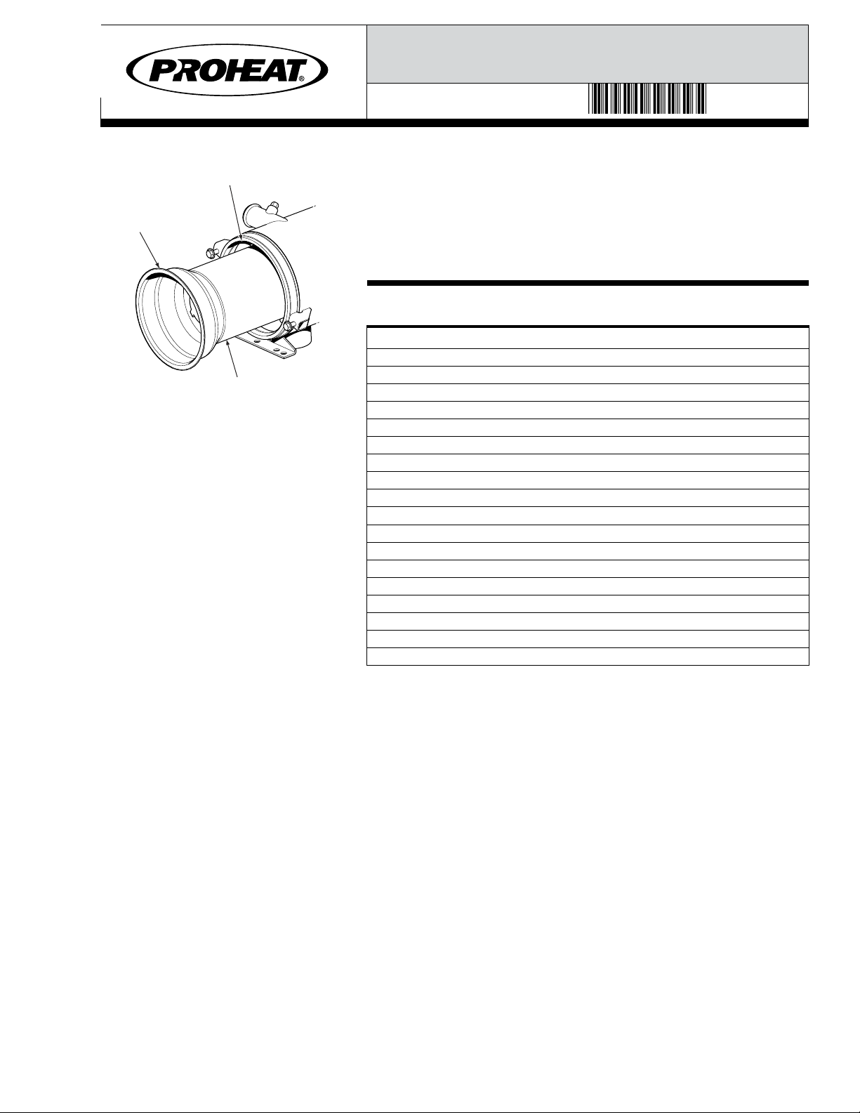
Figure A.
DO NOT discard any component unless
directed to do so. All mounting hardware
will be re-used during the installation
of the compressor kit.
NOTICE
1. Disconnect all harnesses at the PCM.
2. Disconnect the fuel supply line.
3. Referring to figure A, loosen and back out the burner head mounting
bolts (item 1) allowing enough room to rotate the burner head 15°
counter-clockwise and remove.
4.
Remove the blower housing (item 3) by removing the two M6 screws
(item 2). Item 3a may vary in appearance depending on the type of
heater model. Note initial orientation of blower housing.
5.
Remove the combustion air blower (item 5) by removing the retaining
ring (item 4).
6. Disconnect the motor (item 6), fuel solenoid (item 7), and ignition
module (item 8) at the PCM (item 9), then carefully slide off the PCM
to avoid damaging the motor wires.
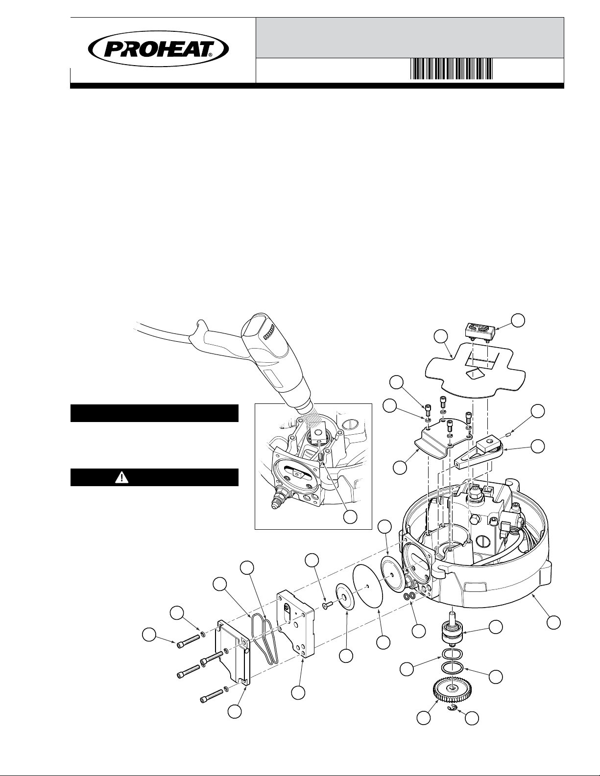
7.
Remove the motor (item 6) by removing the four M6 screws (item 10).
Note initial orientation of motor for reassembly (refer to figure A inset).
8. Remove and discard the Motor Gear (item 11) by removing the
retaining ring (item 4). Ensure Motor Shaft and retaining ring
groove are thoroughly cleaned and free from all green Loctite®
adhesive before reassembly.
9. Turn the Burner head over as shown in figure B. Remove the
ignition electrode (item 28) then the flame shield (item 29).
10. Remove the valve cover (item 18) by removing the four M5 screws
(item 16) and lock washers (item 17).
11. Remove and discard the two O-rings (item 19 & 20) and cylinder
head assembly (item 21).
12. Remove the #8 screw (item 22) from the connecting rod assembly
(item 23), then remove the intake disk (item 24), diaphragm (item
25) and compression disk (item 26).
13. Remove and discard the two O-rings (item 27) from the burner head
flange (item 15).
28
29
31
18
19
21
22
27
12
14
4
13
33
26
15
25
23
32
24
20
30
17
16
17
Figure B.
Heat may be required. Use a heat gun
directed at the screw head (item 32) to
loosen the Loctite®bond.
NOTICE
32
Area must be free from any combustible
fuels when using a heat gun.
WARNING
Copy Part# 206000, Rev. E Page 2 of 9
Date: 05/2017
© 2010 Marine Canada Acquisition Inc. DBA SEASTAR SOLUTIONS 3831 No. 6 Road, Richmond, B.C. Canada V6V 1P6 Tel: 604.270.6899 Web: www.proheat.com
INSTALLATION INSTRUCTIONS

Disassembly Parts Checklist
14. Remove the compressor cover (item 31) by removing the four M5
screws (item 30) and lock washers (item 17).
15. Remove and discard the compressor gear (item 12) by removing
the retaining ring (item 4). Ensure the Compressor Shaft and
retaining ring groove are thoroughly cleaned and free from all
green Loctite®adhesive before reassembly.
16. Remove the internal retaining ring (item 13) and spring washer
(item 14) from the burner head flange (item 15).
17. Remove the #10 set screw (item 32) from the connecting rod
assembly. NOTE:heat may be required. Use a heat gun directed at
the screw head to loosen the Loctite®bond (See figure B inset).
18. Referring to figure C, remove the compressor shaft assembly
(item 33). NOTE: heat may be required. Use a heat gun directed at
bearings to loosen the Loctite®bond, then tap out with a hammer
being careful not to damage the burner head flange (item 15).
19. Slide the connecting rod assembly (item 23) out from the
compressor crankcase.
20. Discard all of the remaining components as per the disassembly
parts checklist.
ITEM RE-USE DISCARD DESCRIPTION QTY UOM
1 X Screw, M8 x 1.25 x 30, HWHCS 2 ea
2 X Screw, M6 x 1 x 1.25, BHSCS SS 2 ea
3 X Blower Housing 1 ea
4 X Retaining Ring 3 ea
5 X Combustion Air Blower 1 ea
6 X Motor 1 ea
7 X Fuel Solenoid 1 ea
8 X Ignition Module 1 ea
9 X Proheat Control Module (PCM) 1 ea
10 X Screw, M6 x 1 x 16, SHCS SS 4 ea
11 X Motor Gear 1 ea
12 X Compressor Gear 1 ea
13 X Snap Ring 1 ea
14 X Spring Washer 1 ea
15 X Burner Head Flange 1 ea
16 X Screw, M5 x 0.8 x 30 SHCS ZP 4 ea
17 X Lockwasher, #10 SS 8 ea
18 X Valve Cover 1 ea
19 X O-Ring, 2-035 1 ea
20 X O-Ring, 2-031 1 ea
21 X Cylinder Head 1 ea
22 X Screw, #8-32 x 1/2, FHSCS SS 1 ea
23 X Connecting Rod Assembly 1 ea
24 X Intake Disk 1 ea
25 X Diaphragm 1 ea
26 X Compression Disk 1 ea
27 X O-Ring, 2-010 2 ea
28 X Ignition Electrodes 1 ea
29 X Flame Shield 1 ea
30 X Screw, M5 x 0.8 x 10, SHCS SS 4 ea
31 X Compressor Cover 1 ea
32 X Set Screw, #10-32 x 3/8, SHSS 1 ea
33 X Compressor Shaft Assembly 1 ea
33
15
Figure C.
Copy Part# 206000, Rev. E Page 3 of 9
Date: 05/2017
© 2010 Marine Canada Acquisition Inc. DBA SEASTAR SOLUTIONS 3831 No. 6 Road, Richmond, B.C. Canada V6V 1P6 Tel: 604.270.6899 Web: www.proheat.com
INSTALLATION INSTRUCTIONS
50
15
34
36
35
37
37
38
FLAT FACE OF
COMPRESSOR
SHAFT TORQUE:
25 ± 3 IN-LBS
GAP
GAP
CONNECTING
ROD
DIAPHRAGM
OPENING
15
37
DRIVE HUB
DIAPHRAGM
OPENING
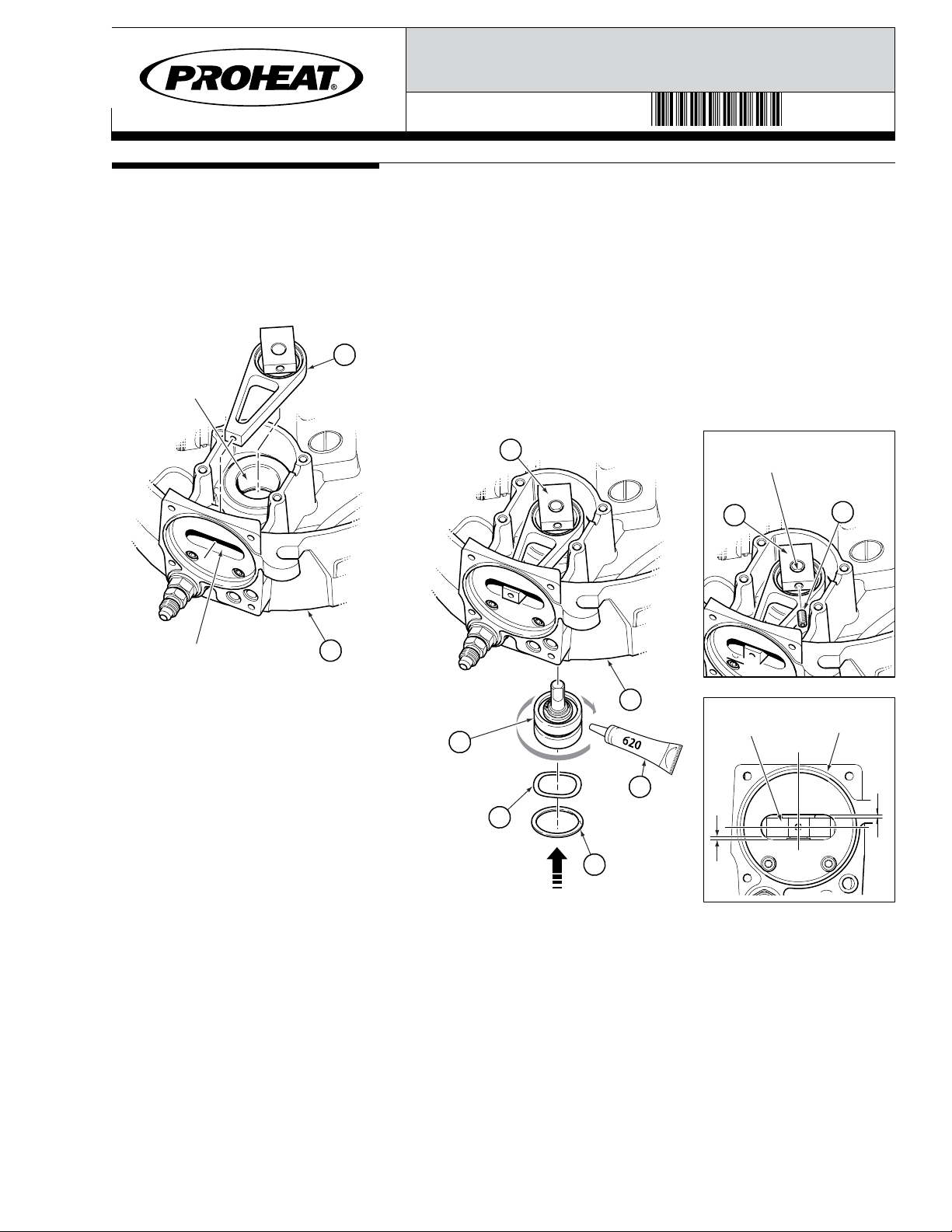
Reassembly Instructions 1. Prep drive hub to ensure it is clean and free from any debris and/
or contaminants. Use of a Scotch Bright pad is permitted.
2. Apply Loctite®620 (item 50) to the outer race of the bearings in
item 34. Ensure no Loctite®contacts the sealing surfaces.
3. Place the connecting rod assembly (item 37) in position as
shown in figure E FIRST. Insert the compressor shaft assembly
(item 34) into the drive hub SECOND. NOTE: the order of this
operation is important.
4. Install the spring washer (item 35) and snap ring (item 36). Ensure
the spring washer sits evenly against the bearing surface, and the
snap ring is properly seated in the groove in the drive hub.
5. Install set screw into the connecting rod assembly ensuring that it
mates flush to flat face of compressor shaft after tightening. If
positioned correctly, the areas marked “gap” will be equal in size
(see figure E insets).
Copy Part# 206000, Rev. E Page 4 of 9
Date: 05/2017
© 2010 Marine Canada Acquisition Inc. DBA SEASTAR SOLUTIONS 3831 No. 6 Road, Richmond, B.C. Canada V6V 1P6 Tel: 604.270.6899 Web: www.proheat.com
INSTALLATION INSTRUCTIONS
figure E.
Figure D.
48
47
SHAFT TO BE
FREE OF ALL
ADHESIVES/
LUBRICANTS
NOTE GEAR
ORIENTATION
SEE INSET
SOFT HAMMER 13 mm DEEP SOCKET
WOOD BLOCK TO
SUPPORT SHAFT
48
TEETH
47
Compressor Gear.
NOTE: ORIENTATION
AS
PER TEXT ON GEAR
39
39
43
42
42
37
15
41
41
40
40
TORQUE:
25 ± 3 IN-LBS
NOTE
ORIENTATION
NOTE ORIENTATION NOTE
ORIENTATION
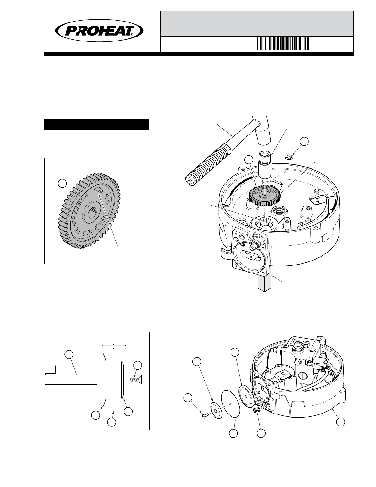
DO NOT apply lubricants or Loctite®to
compressor shaft or gear during
installation.
NOTICE
Figure F.
6. Orient the compressor gear (item 47) as noted in figure F. with
appropriate side facing compressor as per gear text. Install by hand
and secure to the compressor shaft with a new retaining ring
(item 48). If gear cannot be installed by hand, remove the four screws
securing the compressor cover in place and support the compressor
shaft as shown in figure C. A 13 mm deep socket and soft hammer
can then be used to lightly tap gear onto shaft.
7. Install the diaphragm assembly (items 39–42) onto the connecting
rod as shown in figure G. NOTE: orient the intake disk (item 40)
and compression disk (item 42) with the beveled side pointing
away from burner head flange (see figure G inset).
Figure G.
8. Install two O-rings (item 43) into the burner head flange (item 15).
9. Install two O-rings (items 44 and 45) into the valve cover (item 18).
Copy Part# 206000, Rev. E Page 5 of 9
Date: 05/2017
© 2010 Marine Canada Acquisition Inc. DBA SEASTAR SOLUTIONS 3831 No. 6 Road, Richmond, B.C. Canada V6V 1P6 Tel: 604.270.6899 Web: www.proheat.com
INSTALLATION INSTRUCTIONS

37
TDC
ENSURE COUNTER-WEIGHT IS ALIGNED BOTTOM
DEAD CENTER (BDC) BEFORE INSTALLATION
BDC
17
44
46
45
16
18
31
30
17
1
2
3
4
TORQUE SEQUENCE
ENSURE CONNECTING
ROD IS CENTERED IN
DIAPHRAGM OPENING
TORQUE:
27 ± 3 IN-LBS
TORQUE: 27 ± 3 IN-LBS
Figure I.
Figure H.
49
49
48
6
Black Motor Gear
with 38 Teeth.
NOTE: ORIENTATION
AS
PER TEXT ON GEAR
38 TEETH
SHAFT TO BE
FREE OF ALL
ADHESIVES/
LUBRICANTS
WOOD BLOCK
TO
SUPPORT SHAFT
13 mm
DEEP
SOCKET
SOFT
HAMMER
Figure J.
10. Position the connecting rod assembly (item 37) so that it is in
BDC (see figure H), and ensure the diaphragm (item 41) is
concentric to the “diaphragm opening”.
NOTE: this operation is CRITICAL prior to proceeding onto step 11.
11. Install the cylinder head assembly (item 46) and valve cover (item
18) and secure with four M5 screws (item 16) and lock washers
(item 17). Torque the screws according to the torque sequence
shown in figure I inset.
12. Install the compressor cover (item 31) and secure with four screws
(item 30) and lock washers (item 17).
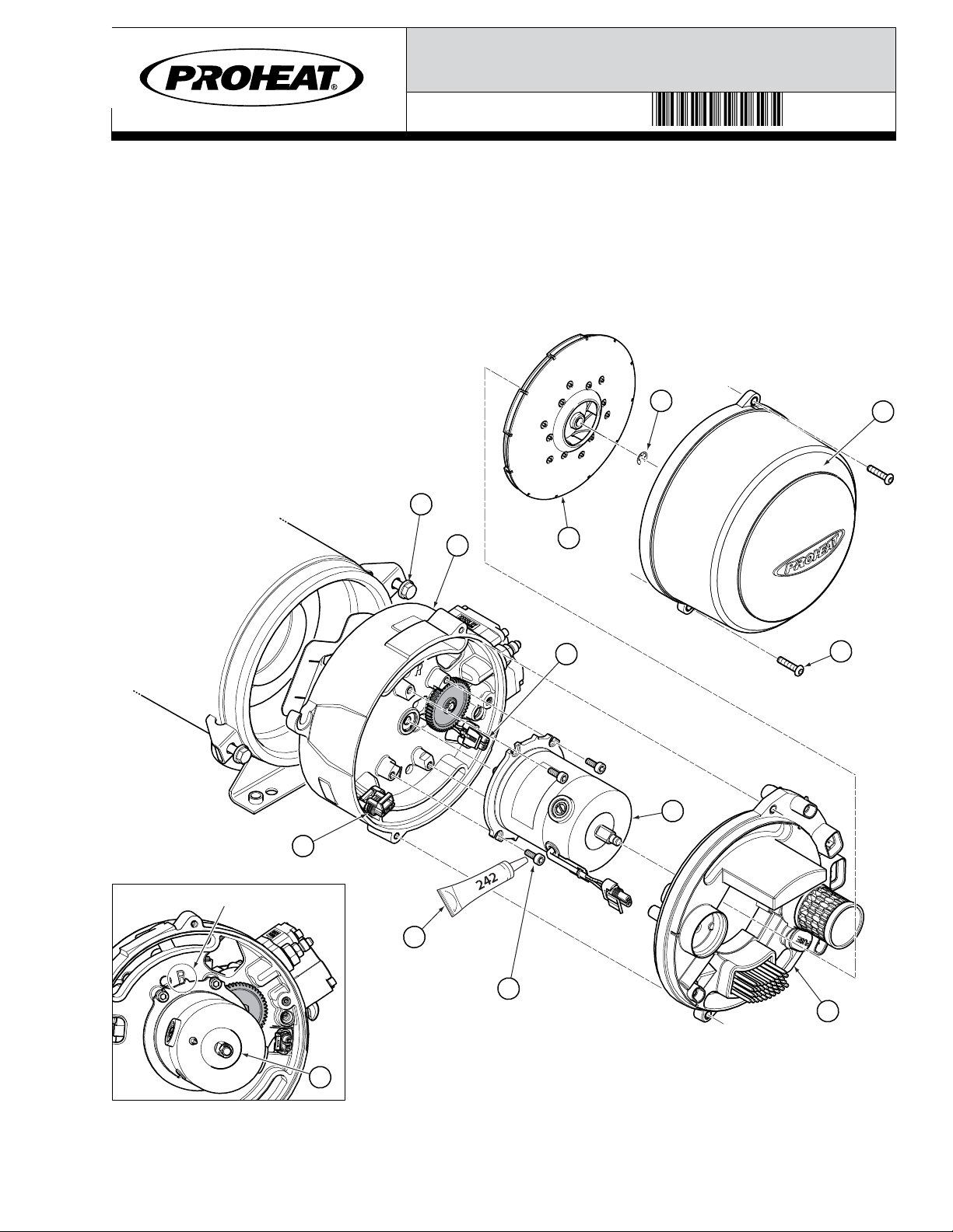
13. Orient the Motor Gear (item 49) as noted in figure J. (Inset) with
appropriate side facing Motor flange as per gear text. Install by hand
and secure to the Motor Shaft with a new retaining ring (item 48).
If gear cannot be installed by hand, a 13 mm deep socket and soft
hammer can be used to lightly tap gear onto shaft. Support Motor
shaft from combustion air blower side as shown in figure J.
Copy Part# 206000, Rev. E Page 6 of 9
Date: 05/2017
© 2010 Marine Canada Acquisition Inc. DBA SEASTAR SOLUTIONS 3831 No. 6 Road, Richmond, B.C. Canada V6V 1P6 Tel: 604.270.6899 Web: www.proheat.com
INSTALLATION INSTRUCTIONS
48
7
1
5
2
9
10
51
APPLY LOCTITE® 242
TO THREADS
TORQUE: 75 ± 7 IN-LBS
6
3
TORQUE:
100 ± 10 IN-LBS
TORQUE:
75 ± 7 IN-LBS
SHOWN IN "R" POSITION
6
15
8
Figure K.
14. Referring to figure K, install the motor (item 6) onto the burner
head flange and secure with four M6 screws (item 10). Ensure to
apply Loctite®242 (item 51) to the screw threads prior to
installation. NOTE: Motor (item 6) must be re-installed according
to its original position (see orientation marks item figure K inset).
15. Install the PCM (item 9), then reconnect the motor (item 6), fuel
solenoid (item 7) and ignition module (item 8) to their respective
terminals. NOTE: Ensure the PCM is reinstalled in its original
orientation.
Copy Part# 206000, Rev. E Page 7 of 9
Date: 05/2017
© 2010 Marine Canada Acquisition Inc. DBA SEASTAR SOLUTIONS 3831 No. 6 Road, Richmond, B.C. Canada V6V 1P6 Tel: 604.270.6899 Web: www.proheat.com
INSTALLATION INSTRUCTIONS

Ensure to rotate combustion air blower
(item 5) by hand until it spins freely.
This seats the fuel pump gear pack
and avoids a Code 12 on startup. For
more information, refer to the manual
at www.proheat.com
NOTICE
PK0036 Digital Manometer or PK0067
Pressure Test Gauge (not shown) is
required to complete the rebuild. It is
NOT supplied in the rebuild kit.
Go to www.proheat.com for more
information.
NOTICE
16. Install the combustion air blower (item 5) and secure with a new
retaining ring (item 48). Spin the combustion air blower by hand
after installation to ensure it spins freely.
17. Install the blower housing (item 3) ensuring correct orientation,
and secure with two screws (item 2).
18. Set Compressor Pressure (refer to figure L).
Refer to M-Series Service Manual at www.proheat.com for detailed
instructions. Air filter and nozzle must be clean for compressor
setting. Inspect air passages of fuel block and clean as required.
MODEL AIR PRESSURE (DIAPHRAGM COMPRESSOR)
M50 6.0 ± 0.1 PSI (41.4 ± 0.7 kPa)
M80/M90 2.9 ± 0.1 PSI (20.0 ± 0.7 kPa)
M105/M125 3.65 ± 0.1 PSI (25.1 ± 0.7 kPa)
19. Install the heat shield (item 29) and ignition electrodes (item 28).
20. Inspect and Clean Heat Exchanger and Combustion Tube.
Remove combustion tube to access the inside of the heat exchanger.
Clean any combustion deposits that may have accumulated on
the heat exchanger fins with a wire brush. Use a vacuum to suck
the combustion deposits out. Ensure that the exhaust pipe is
clean and free from restriction.
Clean the combustion tube with a wire brush. Reinstall combustion
tube into the heat exchanger ensuring that the orientation boss
is at the 12 o’clock position as shown in figure M.
PRESSURE ADJUSTMENT SCREW
DECREASE
PRESSURE
INCREASE
PRESSURE
FLAME
SHIELD
IGNITION
ELECTRODE
ASSEMBLY
DIAPHRAGM
COMPRESSOR
DIGITAL
MANOMETER
(P/N PK0036)
PRESSURE
ADJUSTMENT
SCREW
Figure L.
Flammable. Point Nozzle away from face, open sparks and flames.
WARNING
Copy Part# 206000, Rev. E Page 8 of 9
Date: 05/2017
© 2010 Marine Canada Acquisition Inc. DBA SEASTAR SOLUTIONS 3831 No. 6 Road, Richmond, B.C. Canada V6V 1P6 Tel: 604.270.6899 Web: www.proheat.com
INSTALLATION INSTRUCTIONS
ITEM DESCRIPTION QTY UOM
34 Compressor Shaft Assembly 1 ea
35 Spring Washer 1 ea
36 Snap Ring 1 ea
37 Connecting Rod Assembly 1 ea
38 Set Screw, #10-32 x 3/8, SHSS 1 ea
39 Screw, #8-32 x 1/2, FHSCS SS 1 ea
40 Intake Disk 1 ea
41 Diaphragm 1 ea
42 Compression Disk 1 ea
43 O-Ring, 2-010 2 ea
44 O-Ring, 2-035 1 ea
45 O-Ring, 2-031 1 ea
46 Cylinder Head 1 ea
47 Gear, Compressor, 48 Teeth, Black 1 ea
48 Retaining Ring 3 ea
49 Gear, Motor, 38 Teeth, Black 1 ea
50 Loctite®620 (.5 ml Tube) 1 ea
51 Loctite®242 (.5 ml Tube) 1 ea
Reassembly Parts Checklist
ORIENTATION
BOSS
HEAT EXCHANGER
FLANGE NOTCH
COMBUSTION TUBE
Figure M. 21. Install the burner head back onto the heat exchanger and secure
with two screws (item 1).
22. Operate heater for a minimum of two cycles to ensure functionality.
Inspect for fuel leaks around the exterior of the burner head and
heat exchanger.
Copy Part# 206000, Rev. E Page 9 of 9
Date: 05/2017
© 2010 Marine Canada Acquisition Inc. DBA SEASTAR SOLUTIONS 3831 No. 6 Road, Richmond, B.C. Canada V6V 1P6 Tel: 604.270.6899 Web: www.proheat.com
INSTALLATION INSTRUCTIONS
Other manuals for M Series
2
This manual suits for next models
1
Table of contents
Popular Air Compressor manuals by other brands

Sullair
Sullair 185 Operators manual and parts lists

Fieldmann
Fieldmann FDAK 901521 instruction manual

GEA
GEA HG76e/1620-4 Assembly instructions

AEROTECNICA COLTRI
AEROTECNICA COLTRI MCH-5/EM CNG Use and maintenance manual

General Air Products
General Air Products Q Series Installation, operation and maintenance manual

GLENCO
GLENCO AIRMAC FU SHENG T20 owner's manual


